English
Français
Español
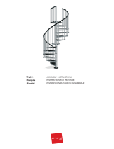
ASSEMBLY INSTRUCTIONS
INSTRUCTIONS DE MONTAGE
INSTRUCCIONES PARA EL ENSAMBLAJE

COD.5199
068076
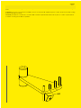
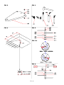
ATTENZIONE: per un corretto serraggio dei grani B20, ruotare la chiave
di circa 90° dal punto di contatto. Una ulteriore inutile rotazione
potrebbe danneggiare il gradino.
ATTENTION: for the correct xing of B20, turn the key around 90° from the contact point. A further additional rotation could damage the
tread.
ATTENTION: pour serrer correctement les vis B20, tourner le clef à environ 90° à partir du point de contact. Un ultérieur et inutile serrage
pourrait endommager la marche.
ATENCIÓN: para apretar correctamente los tornillos B20 es suficiente apretar la llave 90° desde el punto de contacto. Apretar más de
lo indicado es inútil y puede dañar los peldaños.

5 - kl

8 - kl
English
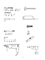
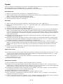
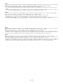
Before starting the assembly process, unpack all components of the staircase. Lay them out on a large surface and
check the quantity of all the pieces, by consulting the table TAB.1 (A = Code, B = Quantity).
Inside the staircase box you will also nd a DVD which we suggest watching before proceeding to assemble.
For customers in the USA there is a customer assistance number 1-888 STAIRKT, which you can telephone in case
of problems.
Preliminary Assembly
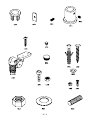
1. Assemble the parts C24, C25 and B20 to the treads (L03) (g. 2).
2. Carefully measure the oor-to-oor height and determine the required number of spacers (D08) (TAB.2) and
prepare them onto their proper spacer (D15) (TAB2)
3. Assemble the parts C63, C65, C66 onto the baluster (C03) (g. 3).
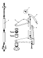
4. Assemble the base G03, B17 and B46 (g. 1).
Assembly
5. Determine and mark on the oor the centre of the opening, then position the base (G03+B17+B46) (g. 4).
6. Drill with 14 mm (
35
/
64
”
) drill bit and x the base (G03+B17+B46) into the oor by means of the parts B13 (g. 1).
7. Screw the pole (G02) into the base (G03+B17+B46) (g. 1).
8. Insert the base plate cover (D12) into the pole (G02) (g. 5).
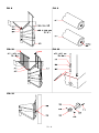
9. Insert the spacers (D08), then the shorter spacer (D14), the spacers (D08), the rst tread (L03) with the wooden
staves parallel to the specied ascending side (g. 5A), the spacers (D08), the spacer (D15), the spacers (D08)
and another tread (L03) and so on. Add alternatively the treads alternately one to the right and one to the left,
so as to distribute the weight in a balanced way (g. 5).
10. When you reach the end of the pole (G02), screw the part B47 on it, then add the second pole (G02) and
continue with the stair assembly (g. 5)
11. When you reach the end of the pole (G02), screw on it the part B46 and the part G01. (Screw the part G01, until
its upper end sticks out approximately 15 cm (5
29
/
32
”
) from the stair height (g. 6). Continue adding the treads,
by using the part D01 inserted into the tread (L03).
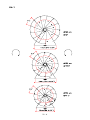
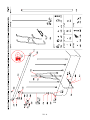
12. Finally add the stair landing (E02). After having chosen the stair rotation (g. 7), position the landing (E02) with
the small hole (which is needed for the baluster passage (C03)) on the arrival side of the treads (L03) (g. 8)
Cut the landing (E02), if necessary, in relation to the oor opening.
13. Insert the parts B05, B04 and screw the part B03 sufciently (g. 1) but keeping in mind that the treads still
have to be rotated (g. 1).
Fitting of the Landing
14. Approach the part F12 to the oor. Determine the position, maintaining a distance of about 15 cm (5
29
/
32
”
) from
the external side of the landing (E02), pierce with a 14 mm (
35
/
64
”
) drill bit and x securely by using the part B13
(g. 1).
15. Fix the parts F12 to the landing (E02), by using the parts C58 (pierce the landing (E02) with the 5 mm (
35
/
64
”
) drill bit.
16. Position the parts B95.
Assembly of the Railing
17. Spread-out the treads (L03) fan-like. It is now possible to use the stair.
18. Starting from the landing (E02), insert the longer railing balusters C03 (H. 1190 mm - 46
7
/
8
”
), that build the
connection between the treads (L03). Keep the balusters C03 (H. 1190 mm - 46
7
/
8
”
) with the part C63 and the
pierced part to the top (g. 8). Tighten only the part B20 of the lower tread (g. 2).
19. Check very carefully the vertical position of the inserted balusters C03. This control is very important for insuring
the best results.
20. Tighten securely the part B03 (g. 8).
21. Tighten securely the part B02 of the upper tread (g. 2).
22. Check once more the vertical position of the railing balusters C03 (H. 1190 mm - 46
7
/
8
”
) and, if necessary,
correct it, by repeating the previous operations.
23. Position the rst baluster C03 (H. 1190 mm - 46
7
/
8
”
). Cut one long baluster C03 (H. 1190 mm - 46
7
/
8
”
) to
obtain the same size as all others you assembled previously.
24. Fix into the oor in relation to the rst baluster (C03) (H. 1190 mm - 46
7
/
8
”
), the part F01, by piercing with the 8
mm (
5
/
16
”
) diameter bit. Use the parts C58, B12, B83 and B02 (g. 1). Then assemble the reinforcing part (F07).

9 - kl
25. Find the handrail piece not marked in red colour (A13) and the one marked in red colour (A14) which will be used
for the railing of the landing (E02) (g. 9).
26. Start to model the handrail pieces (A13) not marked in red colour, trying to give it a shape that corresponds the
nearest possible to the curve of the staircase (g. 1).
27. Beginning from the baluster (C03) on the landing (E02), start to fasten the handrail (A13), that you have already
slightly bent in the previous operation. Use the parts C64 together with the screw driver.
Warning: position the join line of the handrail covering downwards.
28. Connect all other handrail pieces (A13), by screwing, glueing and shaping them. Use the parts B33 and D72.
29. When you reach the rst baluster (C03) at the bottom of the stair, cut the excess piece of the handrail with a
hacksaw.
30. Complete the handrail (A13) by assembling the part A12. Use the parts C64 and the glue (X01) (g. 1).
31. Insert all remaining railing balusters into the treads (L03), tighten the part B20 and x to the handrail (A13),
paying careful attention to the vertical position. (for the stairs with a diameter larger than 140 cm (55
1
/
8
”
), we
suggest that you rst assemble the shorter balusters) (g. 10). According to the geometrical characteristics of
the staircase, the intermediate balusters may protrude from the lower part of the step, in which case we advise
cutting them off level with the step to obtain a more attractive nish.
32. Check again the regular shape of the handrail (A13) and, if necessary, correct it with a rubber hammer.
33. Complete the railing assembly by tting the parts B82 into the lower part of the balusters (C03) and the parts
C19 into the lateral part of the treads (g. 1).
Assembly of the Balustrade
34. Screw the baluster (C04) into the part G01 that sticks out from the landing (E02) (g. 8).
35. Set the parts F01, by using the parts C58, B83, B02 onto the landing (E02). Pierce with the 5 mm (
13
/
64
”
) drill bit
the landing (E02), maintaining a similar distance between the holes as the one between the already assembled
railing balusters (C03).
36. Set the shorter balusters C03 (H. 935 mm - 36
13
/
16
”
) and tighten the part B02 (g. 1)
37. Fix the part A15 into the baluster (C04), by using the part B02 (g. 1).
38. Fix the handrail (A14) marked in red colour, using the parts C64 (g. 1).
39. In case there were walls around the stair well and on their position, it could be necessary to position one or two
more balusters C03 (H. 935 mm - 36
13
/
16
”
) (g. 10).
40. In that case it is necessary to consider either the distance between all other balusters, or otherwise the
distance from the wall. For the xing it is suggested to pierce the landing (E02) with the 5 mm (
13
/
64
”
) drill bit
and to use the xing parts F01, C58, B83, B02. Whereas for the xing into the oor it is suggested to pierce the
oor with the 12 mm (
15
/
32
”
) drill bit and to use the parts F01, B02, B87 (g. 11). In case it is necessary to join
the landing baluster to the oor- mounted baluster, (g. 10), shape the handrails carefully, following the curves.
If wrinkles should form on the inside of the handrails, this is not a defect. Rubbing the area energetically with a
paper napkin (to generate heat) will cause them to disappear.
Final Assembly
41. In order to re-inforce the staircase at the intermediate points, you must x into the wall the parts F09 and
connect them to the balusters (C03) by means of the parts F08. Pierce the wall with the 8 mm (
5
/
16
”
) drill bit and
use the parts C50, C49, C58, B12 (g. 12).
After you have nished assembling the staircase,
please visit our website and send us your suggestions: www.arke.ws

12 - kl
Français
Avant de commencer le montage, il faut déballer tous les éléments de l’escalier. Il faut les poser sur une grande
surface et vérier la quantité des éléments (TAB. 1: A = Code, B = Quantité).
Vous trouverez dans le matériel livré un DVD que nous vous conseillons de regarder préalablement.
Assemblage préliminaire
1. Assembler les éléments C24, C25 et B20 dans les marches (L03) (g. 2).
2. Mesurer attentivement la hauteur sol à sol an de déterminer la quantité des entretoises (D08) et de les
préparer sur la propre entretoise (D15) (TAB. 2).
3. Assembler les éléments C63, C65, C66 à la colonnette (C03) (g. 3).
4. Assembler la base G03, B17 et B46 (g. 1).
Assemblage
5. Déterminer le centre de la trémie au sol et positionner la base (G03+B17+B46) (g. 4).
6. Percer avec la mèche de diamètre 14 mm (
35
/
64
”
) et xer la base (G03+B17+B46) au sol avec les éléments B13
(g. 1).
7. Visser le pylône (G02) sur la base (G03+B17+B46) (g. 1).
8. Insérer la couvre-base (D12) dans le pylône (G02) (g. 5).
9. Insérer, dans l’ordre, les entretoises (D08), l’entretoise la plus courte (D14), les entretoises (D08), la première
marche (L03) (de manière à ce que les lattes de bois soient parallèles au côté de la montée préétabli (g. 5A),
les entretoises (D08), l’entretoise (D15), les entretoises (D08) et de nouveau, la marche (L03) en continuant.
Disposer les marches altérnativement à droite et à gauche, an de distribuer uniformément le poids (g. 5).
10. A la n du pylône (G02), visser l’élément B47, visser le pylône (G02) suivant et continuer à assembler l’escalier
(g. 5).
11. A la n du pylône (G02), visser l’élément B46 et l’élément G01 (visser l’élément G01 en considérant qu’il doit
dépasser la hauteur de l’escalier d’environ 15 cm (5
29
/
32
”
) (g. 6). Continuer à insérer les marches en employant
l’élément D01 inséré dans la marche (L03).
12. Insérer le palier (E02) en dernier. Après avoir choisi le sens de rotation (g. 7), positionner le palier (E02) avec le
petit trou (qui servira au passage de la colonnette (C03)) sur le côte d’arrivé des marches (L03) (g. 8). Couper
le palier (E02), si nécessaire, en considérant les dimensions de la trémie.
13. Insérer les éléments B05, B04 et serrer l’élément B03 sufsemment, en considérant que les marches doivent
encore tourner (g. 1).
Fixation du palier
14. Approcher l’élément F12 au plancher. Déterminer la position, en maintenant une distance d’environ 15 cm (5
29
/
32
”
)
du bord extérieur du palier (E02), percer avec la mèche de diamètre 14 mm (
35
/
64
”
) et xer dénitivement en
employant les éléments B13 (g. 1).
15. Fixer les éléments F12 au palier (E02), en employant les éléments C58 (percer le palier (E02) avec une mèche
de diamètre 5 mm (
13
/
64
”
).
16. Positionner les éléments B95.
Assemblage du garde-corps
17. Disposer les marches en éventail (L03). Il est maintenant possible de monter sur l’escalier.
18. En commençant du palier (E02) insérer les colonnettes plus longues (C03) (H. 1190 mm - 46
7
/
8
”
) qui unissent
les marches (L03). Orienter les colonnettes (C03) (H. 1190 mm - 46
7
/
8
”
) en tenant la partie percé de l’élément
C63 en haut (g. 8). Serrer seulement l’élément B20 de la marche inférieure (g. 2).
19. Contrôler la ligne verticale de toutes les colonnettes (C03) posés. Faire attention à cette opération parce qu’elle
détermine le bon résultat de l’assemblage.
20. Serrer dénitivement l’élément B03 (g. 8).
21. Serrer dénitivement l’élément B20 de la marche supérieure (g. 2).
22. Contrôler de nouveau la ligne verticale des colonnettes (C03) (H. 1190 mm - 46
7
/
8
”
) et la corriger
éventuellement en répétant les opérations précédentes.
23. Positionner la première colonnette (C03) (H. 1190 mm - 46
7
/
8
”
). Egaliser la longueur d’une colonnette longue
(C03) (H. 1190 mm - 46
7
/
8
”
), en coupant l’extrémité, à la même longueur des autres colonnettes qui viennent
d’être assemblés (g. 1).
24. Fixer au sol, par rapport à la première colonnette (C03) (H. 1190 mm - 46
7
/
8
”
), l’élément F01, en perçant avec la

13 - kl
mèche de diamètre 8 mm (
5
/
16
”
). Employer les éléments C58, B12, B83 et B02 (g. 1). Assembler l’élément de
renfort (F07)
25. Identier les segments de main courante non marqués de rouge (A13) et celui marqué de couleur rouge (A14)
palier (E02) (g. 9).
26. Commencer à modeler les mains courantes (A13), non marqués de rouge en essayant de lui donner une
courbure qui suive le mieux celle de l’escalier (g. 1).
27. En commençant de la colonnette (C03) du palier (E02), commencer à xer la main courante (A06), qui vient
d’être courbé. Employer les éléments C64, avec la visseuse.
Attention: placer la ligne de jonction du revêtement de la main courante vers le bas.
28. Unir les autres pièces de main courante (A13), en les vissant, les collant et les modelant de suite. Employer les
éléments B33 et D72.
29. Par rapport à la première colonnette (C03) de l’escalier, couper la main courante en trop avec une scie à
métaux.
30. Compléter la main courante (A13) en xant l’élément A12, en employant les éléments C64 et la colle (X01) (g. 1).
31. Insérer toutes les autres colonnettes dans les marches (L03), serrer l’élément B20 et xer à la main courante
(A13) en faisant attention à leur ligne verticale (pour les modèles avec un diamètre plus grand que 140 cm
(55
1
/
8
”
), nous conseillons d’assembler avant les colonnettes plus courtes) (g. 10). Selon les caractéristiques
géométriques de l’escalier, les colonnettes intermédiaires pourraient dépasser de la partie inférieure de la
marche, nous vous conseillons dans ce cas de couper la marche le long de l’arête an d’obtenir un montage
selon les règles de l’art.
32. Contrôler de nouveau la linéarité de la main courante (A13) et la corriger éventuellement en employant un
marteau en gomme.
33. Compléter l’assemblage du garde-corps, en insérant les éléments B82 dans la partie inférieure des colonnettes
(C03) et les éléments C19 dans la partie latérale des marches (g. 1).
Assemblage de la balustrade
34. Visser la colonne (C04) sur l’élément G01 qui dépasse le palier (E02) (g. 8).
35. Positionner les éléments F01, en employant les éléments C58, B83, B02 sur le palier (E02). Percer avec la
mèche de diamètre 5 mm (
13
/
64
”
) le palier (E02), en maintenant presque la même distance entre les trous
comme celle entre les colonnettes (C03) du garde-corps qui vient d’être assemblé.
36. Positionner les colonnettes plus courtes (C03) (H. 935 mm - 36
13
/
16
”
) et serrer l’élément B02 (g. 1).
37. Fixer l’élément A15 sur la colonne (C04) en employant l’élément B02 (g. 1)
38. Fixer la main courante (A14) marqué de rouge, en employant les éléments C64 (g.1).
39. Selon la position et l’existence de murs autour de la trémie de l’escalier, il pourrait être nécessaire de
positionner une ou deux colonnettes (C03) (H. 935 mm - 36
13
/
16
”
) de plus (g. 10).
40. Dans ce cas, il est nécessaire de considérer la même distance comme celle entre les autres colonnettes ou
vers le mur. Pour la xation il est conseillé de percer le palier (E02) avec une mèche de diamètre 5 mm (
13
/
64
”
)
et d’employer les éléments F01, C58, B83, B02 tandis qu’il est conseillé de percer le sol avec la mèche de
diamètre 12 mm (
15
/
32
”
) et d’employer les éléments F01, B02, B87 (g. 11).
S’il est nécessaire de raccorder la balustrade du palier à la balustrade au sol, (g. 10), modeler les mains
courantes, en faisant attention à bien raccorder les courbes. Si des plis se forment sur le côté interne des
mains courantes, il ne s’agit pas d’un défaut, il faut alors frotter énergiquement (en produisant de la chaleur) la
partie avec une serviette en papier jusqu’à ce que ces plis disparaissent.
Assemblage final
41. An de rendre plus rigide l’escalier dans les points intermédiaires, il faut xer au mur les éléments F09 et les
unir, en employant les éléments F08, avec les colonnettes (C03). Percer avec la mèche de diamètre 8 mm (
5
/
16
”
)
et employer les éléments C50, C49, C58, B12 (g. 12).
Une fois le montage terminé, nous vous invitons à nous envoyer vos suggestions
en visitant notre Site Internet www.arke.ws

14 - kl
Español
Antes de empezar el ensamblado de la escalera, desembalar todas las piezas de la escalera. Colocarlas de manera
que pueda vericarse las cantidades (TAB. 1: A = Código, B = Cantidad).
En el embalaje encontrareis un DVD que aconsejamos de ver antes de empezar.
Ensamblaje previo
1. Montar los elementos C24, C25 y B20 en los peldaños (L03) (g. 2).
2. Medir cuidadosamente la altura de pavimento a pavimento para determinar la cantidad de discos distanciadores
(D08) y colocarlos sobre cada distanciador (D15) (TAB.2)
3. Montar los elementos C63, C65, C66 al barrote (C03) (g. 3).
4. Montar la placa base G03, B17 y B46 (g. 1)
Ensamblaje
5. Hallar el centro del hueco sobre el pavimento y colocar la base (G03 + B17 + B46) (g. 4)
6. Taladrar con una broca de diámetro 14 mm (
35
/
64
”
) y jar la base (G03 + B17 + B46) al pavimento con los elementos
B13 (g. 1).
7. Atornillar el tubo (G02) a la base (G03 + B17 + B46) (g. 1)
8. Introducir el cubre placa (D12) en el tubo (G02) (g. 5)
9. Introducir en orden los discos distanciadores (D08), el distanciador mas corto (D14), los discos distanciadores
(D08), el primer peldaño (L03) (con las tablas de madera paralelas al lado de subida preestablecido (g. 5A),
los discos distanciadores (D08), un distanciador (D15), los discos distanciadores (D08) y de nuevo el peldaños
(L03) y así sucesivamente. Ir colocando los peldaños alternativamente a derecha e izquierda, para distribuir, así
el peso uniformemente.
10. Alcanzado el extremo del tubo (G02) atornillas el elemento B47, atornillar el tubo (G02) siguiente y seguir
ensamblando la escalera (g. 5)
11. Alcanzado el extremo del tubo (G02), atornillar el elemento B46 y el elemento G01 (atornillar el elemento G01
teniendo en cuenta que debe sobrepasar la altura de la escalera de unos 15 cm (5
29
/
32
”
). Seguir introduciendo
los peldaños utilizando el elemento D01 introducido en el peldaño (L03).
12. Por ultimo introducir la meseta (E02). Tras haber elegido el sentido de rotación (g. 7), colocar la meseta
(E02) con el oricio pequeño (necesario para que el barrote (C03) la atraviese) hacia el lado de llegada de los
peldaños (L03) (g. 8). Cortar la meseta (E02), si fuera necesario, considerando las medidas del hueco del
forjado.
13. Introducir los elementos B05, B04 y apretar el elemento B03 sucientemente, teniendo en cuenta que los
peldaños deben poder moverse (g. 1)
Fijación de la meseta
14. Atornillar el elemento F12 al forjado. Determinar la posición, manteniendo una distancia de 15 cm (5
29
/
32
”
) mas
o menos, desde el borde exterior de la meseta (E02), taladrar con una broca de diámetro 14 mm (
35
/
64
”
) y jar
denitivamente utilizando los elementos B13 (g. 1).
15. Fijar los elementos F12 a la meseta (E02), utilizando los elementos C58 (taladrar la meseta (E02) con una
broca de diámetro 5 mm (
13
/
64
”
).
16. Presentar los elementos B95.
Montáje de la barandilla
17. Abrir los peldaños (L03) en abanico. Ahora es posible subir por la escalera.
18. Empezar por la meseta (E02) adaptar el primer barrote largo (C03) (H. 1190 mm - 46
7
/
8
”
) de unión entre los
peldaños (L03). Orientar los barrotes (C03) (H. 1190 mm - 46
7
/
8
”
) con el elemento C63 con la parte agujereada
hacia arriba (g. 8). Apretar solamente el elemento B20 del peldaño inferior.
19. Comprobar la verticalidad de todos los barrotes (C03) colocados. Tener mucho cuidad en este paso porqué es
muy importante para tener un buen resultado del Montáje.
20. Apretar denitivamente el elemento B03 (g. 8).
21. Apretar denitivamente los elementos B20 de los peldaños superiores (g. 2).
22. Volver a controlar la verticalidad de los barrotes (C03) (H. 1190 mm - 46
7
/
8
”
) y corregirla, si fuera necesario,
repitiendo las operaciones anteriores.
23. Colocar el primer barrote (C03) (H. 1190 mm - 46
7
/
8
”
). Adaptar la altura de un barrote largo (C03) (H. 1190 mm
- 46
7
/
8
”
), cortando un extremo, a la altura de los barrotes recién ensamblados (g. 1).

15 - kl
24. Fijar sobre el pavimento, coincidiendo con el primer barrote (C03) (H. 1190 mm - 46
7
/
8
”
), el elemento F01,
taladrando con una broca de diámetro 8 mm (
5
/
16
”
). Utilizar los elementos C58, B12, B83 y B02 (g. 1). Montar
el elemento de refuerzo (F07).
25. Separar los tramos de pasamanos que no estén marcados con rojo (A13) y el que esté marcado con rojo (A14)
que se utilizará en el rellano (E02) (g. 9).
26. Empezar a modelar los pasamanos (A06) que no estén marcados con rojo intentando darles la misma curvatura
de la escalera (g. 1).
27. Empezar por el barrote (C03) de la meseta (E02), iniciar a jar el pasamanos (A06), ya doblado utilizando los
elementos C64 con el atornillador.
Atención: colocar la línea de unión del revestimiento del pasamanos hacia abajo.
28. Unir los demás tramos de pasamanos (A13), roscandolos pegandolos y moldeandolos sucesivamente. Utilizar
los elementos B33 y D72.
29. A la altura del primer barrote (C03) de la escalera, cortar el pasamanos en exceso con una segueta metálica.
30. Completar el pasamanos (A13) jando los elementos A12, utilizando el elemento C64 y el pegamento (X01)
(g. 1)
31. Montar los demás barrotes en los peldaños (L03), apretando el elemento B20 y jar el pasamanos (A13)
cuidando su verticalidad (para los modelos de diámetro superior a 140 cm (55
1
/
8
”
), aconsejamos montar antes
los barrotes más cortos) (g. 10). Dependiendo de las características geométricas de la escalera, los barrotes
intermedios podrían sobresalir por la parte inferior del peldaño, en este caso, aconsejamos cortar al ras del
peldaño para obtener un montaje perfecto.
32. Controlar la curvatura del pasamanos (A13) y posiblemente corregirla utilizando un martillo de goma.
33. Completar el Montáje de la barandilla, introduciendo los elementos B82 de la parte inferior de los barrotes
(C03) y los elementos C19 en la parte lateral de los peldaños (g. 1).
Montáje de la balaustrada
34. Atornillar la columna (C04) al elemento G01 que asoma de la meseta (E02) (g. 8).
35. Colocar los elementos F01, utilizando los elementos C58, B83, B02 sobre la meseta (E02). Taladrar la meseta
(E02) con una broca de diámetro 5 mm (
13
/
64
”
), manteniendo una distancia entre ejes similar a la existente entre
los barrotes (C03) de la barandilla ensamblada anteriormente.
36. Colocar los barrotes más cortos (C03) (H. 935 mm - 36
13
/
16
”
) y apretar el elemento B02 (g. 1).
37. Fijar el elemento A15 sobre la columna (C04) utilizando el elemento B02 (g. 1.
38. Fijar el pasamanos (A14) marcado con rojo utilizando los elementos C64 (g. 1).
39. Según la posición y la presencia de paredes alrededor del hueco de la escalera podría ser necesario colocar uno
o dos barrotes (C03) (H. 935 mm - 36
13
/
16
”
) más (g. 10).
40. En este caso es necesario considerar un espacio equidistante entre los demás barrotes y la pared. Para
la jación es recomendable taladrar la meseta (E02) con una broca de diámetro 5 mm (
13
/
64
”
) y utilizar los
elementos F01, C58, B83, B02 en cambio es recomendable taladrar el pavimento con una broca de diámetro
12 mm (
15
/
32
”
) y utilizar los elementos F01, B02, B87 (g. 11). En caso de que fuera necesario, acoplar la
balaustrada de la meseta con la balaustrada del pavimento (g. 10), modelar los pasamanos con cuidado,
realizando curvas acopladas correctamente. Si se crean rugosidades en el lado interno del pasamanos, no se
trata de un defecto: frotar con fuerza (produciendo calor) esa parte con una servilleta de papel hasta que sean
eliminadas.
Montáje final
41. Para darle mayor rigidez a la escalera en los puntos intermedios, jar al muro los elementos F09 y unirlos,
utilizando los elementos F08, con los barrotes (C03). Taladrar con una broca de diámetro 8 mm (
5
/
16
”
) y utilizar
los elementos C50, C49, C58, B12 (g. 12).
Terminado el montaje, le invitamos a enviarnos su opinión y sugerencias
visitando nuestro sitio de Internet www.arke.ws

44 - kl
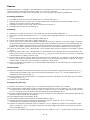
A
B
Ø 120 cm Ø 140 cm Ø 160 cm
47
1
/
4
”
55
1
/
8
”
63
”
A12 3 3 3
A13 5 5 5
A14 1 1 1
A15 2 2 2
B02 13 15 15
B03 1 1 1
B04 1 1 1
B05 1 1 1
B12 7 7 10
B13 6 6 6
B17 1 1 1
B20 40 52 52
B33 6 6 6
B46 2 2 2
B47 1 1 1
B82 24 36 36
B83 9 11 11
B95 3 3 3
C03 H. 1190 mm - 46
7
/
8
”
13 13 13
C03 H. 1130 mm - 44
1
/
2
”
0 12 12
C03 H. 1095 mm - 43
1
/
8
”
12 0 0
C03 H. 1060 mm - 41
3
/
4
”
0 12 12
C03 H. 935 mm - 36
13
/
16
”
8 10 10
C04 1 1 1
C19 40 52 52
C23 2 2 2
C24 72 101 101
C25 40 52 52
C49 2 2 3
C50 2 2 3
C58 21 23 26
C63 33 47 47
C64 73 101 101
C65 33 47 47
C66 33 47 47
D01 4 6 6
D08 119 119 119
D12 1 1 1
D14 1 1 1
D15 12 12 12
D72 5 5 5
E02 1 1 1
F01 9 11 11
F07 1 1 1
F08 2 2 3
F09 2 2 3
F12 3 3 3
G01 1 1 1
G02 2 2 2
G03 1 1 1
L03 12 12 12
X01 1 1 1
TAB 1

45 - kl

46 - kl
Italiano
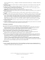
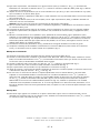
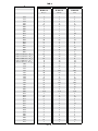
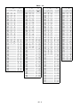
Per determinare la quantità necessaria dei dischi distanziatori (D08) utilizzare la TAB. 2 (H = altezza, A = alzate, X = numero dei dischi distanziatori
(D08) da posizionare sul distanziatore (D15), Y = numero dei dischi distanziatori (D08) da posizionare sul distanziatore (D14)).
Esempio: per un’altezza misurata da pavimento a pavimento di 298 cm e una scala con 13 gradini occorre:
1. In corrispondenza dell’altezza (298 cm), nella colonna H), leggere la quantità dei dischi distanziatori necessari (X = 6, Y = 12, nella colonna
A/13).
2. Distribuire i dischi distanziatori (D08), nel modo seguente: 6 dischi distanziatori (D08) su ogni distanziatore (D15) posizionandone 3 sopra e 3
sotto, 12 dischi distanziatori (D08) sull’unico distanziatore (D14), il più corto, posizionandone 3 sopra e 9 sotto.
English
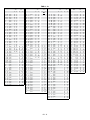
To determine the necessary number of spacers (D08), you must look-up the table TAB.2 (H = Height, A = Rises, X = quantity of spacers (D08) to
position onto the spacer (D15), Y = quantity of the spacers (D08) to position onto the spacer (D14).
Example: given a oor-to-oor height of 298 cm (117
5
/
16
”)
and a staircase with 13 treads, you must proceed as follows;
1. At height (298 cm (117
5
/
16
”) in the row H) look-up the number of necessary spacers (X=6, Y=12, in the row A/13).
2. Distribute the spacers (D08), as follows: 6 spacers (D08) onto every spacer (D15) positioning three spacers on the top and three spacers on the
bottom, twelve spacers (D08) onto the only spacer (D14), the shortest one, positioning three on the top and nine on the bottom.
Français
An de déterminer la quantité nécessaire des entretoises (D08) employer le TAB. 2 (H = hauteur totale, A = hauteurs, X = numéro des entretoises
(D08) à positionner sur l’entretoise (D15), Y = numéro des entretoises (D08) à positionner sur l’entretoise (D14)).
Exemple; pour une hauteur sol à sol mesuré de 298 cm (117
5
/
16
”) et un escalier avec 13 marches il faut:
1. Par rapport à la hauteur (298 cm (117
5
/
16
”), dans la colonne H), lire la quantité des entretoises nécessaires (X = 6, Y = 12, dans la colonne A/13)
2. Distribuer les entretoises (D08), à la manière suivante: 6 entretoises (D08) sur chaque entretoise (D15) en positionnant 3 au-desus et 3 au-
dessous, 12 entretoises (D08) sur l’unique entretoise (D14), la plus courtes, en y positionnant 3 au-dessus et 9 au-dessous.
Español
Para determinar la cantidad necesaria de discos distanciadores (D08) utilizar la TABLA 2 (H =altura, A = tabicas, X = numero de discos
distanciadores (D08) a colocar sobre los distanciadores (D15), Y = numero de discos distanciadores (D08) a colocar sobre el distanciador (D14).
Ejemplo: para una altura de pavimento a pavimento de 298 cm (117
5
/
16
”) y una escalera con 13 peldaños es necesario;
1. En la línea de la altura (298 cm (117
5
/
16
”), en la columna H), leer la cantidad de discos distanciadores necesarios (X = 6, Y = 12, en la columna A/13).
2. Distribuir los discos distanciadores (D08), de la siguiente manera: 6 discos distanciadores (D08) sobre cada distanciador (D15) colocando 3
arriba y 3 abajo, 12 discos distanciadores (D08) sobre el único distanciador (D14), él mas corto, colocar 3 discos arriba y 9 abajo.

48 - kl
H A H
A
H A
H A
10 11
12 13 14 15 16
X Y X Y
X Y X Y
X Y
X Y X Y
KIT
210 0 2 253 0 5 296 0 7 338 0 5
211 0 6 254 0 8 297 0 10 339 0 9
212 0 9 255 0 12 298 1 1 340 0 12
213 1 3 256 1 4 299 1 4 341 11 1
214 1 7 257 1 7 300 1 7 342 1 4
215 2 1 258 1 11 301 1 11 343 1 7
216 2 4 259 2 2 302 2 1 344 1 10
217 2 8 260 2 6 303 2 4 345 1 13
218 3 2 261 2 10 304 2 8 346 2 2
219 3 5 262 3 2 305 2 11 347 2 5
220 3 9 263 3 5 306 3 1 348 2 9
221 4 3 264 3 9 307 3 5 349 2 12
222 4 6 265 3 12 308 3 8 350 2 15
223 5 1 266 4 4 309 3 11 351 3 4
224 5 4 267 4 8 310 4 2 352 3 7
225 5 7 268 4 11 311 4 5 353 3 10
226 6 2 269 5 3 312 4 8 354 3 13
227 6 5 270 5 7 313 4 11 355 4 2
228 6 8 271 5 10 314 5 2 356 4 5
229 7 3 272 6 2 315 5 5 357 4 9
230 7 6 273 6 6 316 5 8 358 4 12
231 7 9 274 6 9 0 4 317 5 12 0 6 359 4 15
232 8 4 0 6 275 6 12 0 8 318 6 2 0 9 360 5 4
233 8 7 0 9 276 7 5 0 11 319 6 6 0 12 361 5 7
234 8 10 0 12 277 7 8 1 2 320 6 9 1 2 362 5 10
235 8 14 1 6 278 7 11 1 6 321 6 12 1 5 363 5 12
236 1 9 279 8 4 1 9 322
7 3 1 9 364 6 2
237 1 12 280 8 7 1 12 323 7 6 1 12 365 6 5
238 2 6 281 8 10 2 4 324 7 9 2 1 366 6 9
239 2 9 282 8 13 2 7 325 7 12 2 5 367 6 12
240 2 12 283 2 10 326 8 3 2 8 368 6 14
241 3 6 284 3 2 327 8 6 2 11 369 7 4
242 3 9 285 3 5 328 8 9 3 1 370 7 7
243 3 12 286 3 8 329 8 12 3 4 371 7 9
244 4 6 287 3 12 330 8 15 3 7 372 7 10
245 4 9 288 4 3 331 3 11 373 7 12
246 4 12 289 4 6 332 3 14 374 8 5
247 5 6 290 4 10 333 4 3 375 8 9
248 5 9 291 5 1 334 4 7 376 8 12
249 5 12 292 5 4 335 4 10
377 8 15
250 6 6 293 5 8 336 4 13
251 6 9 294 5 11 337 5 3
252 6 12 295 6 2 338 5 6
253 7 6 296 6 6 339 5 9
254 7 9 297 6 9 340 5 12
255 7 12 298 6 12 341 6 2
256 8 6 299 7 4 342 6 5
257 8 9 300 7 7 343 6 9
258 8 12
301 7 10 344 6 12
302 8 2 345 7 1
303 8 5 346 7 5
304 8 8 347 7 8
305 8 12 348 7 11
306 8 14
349 8 1
350 8 4
351 8 7
352 8 11
353 8 13
TAB 2 - cm

49 - kl
H A H A H A A
10 11 12 13 14 15 H 16
X Y X Y X Y X Y X Y X Y X Y
KIT
6' 10 5/8" 0 2 8' 3 5/8" 0 5 9' 8 1/2" 0 7 11' 1 1/8" 0 5
6' 11 1/8" 0 6 8' 4 " 0 8 9' 8 7/8" 0 10 11' 1 1/2" 0 9
6' 11 1/2" 0 9 8' 4 3/8" 0 12 9' 9 3/8" 1 1 11' 1 7/8" 0 12
6' 11 7/8" 1 3 8' 4 3/4" 1 4 9' 9 3/4" 1 4 11' 2 1/4" 11 1
7' 1/4" 1 7 8' 5 1/8" 1 7 9' 10 1/8" 1 7 11' 2 5/8" 1 4
7' 5/8" 2 1 8' 5 5/8" 1 11 9' 10 1/2" 1 11 11' 3 " 1 7
7' 1 " 2 4 8' 6 " 2 2 9' 10 7/8" 2 1 11' 3 3/8" 1 10
7' 1 3/8" 2 8 8' 6 3/8" 2 6 9' 11 1/4" 2 4 11' 3 7/8" 1 13
7' 1 7/8" 3 2 8' 6 3/4" 2 10 9' 11 3/4" 2 8 11' 4 1/4" 2 2
7' 2 1/4" 3 5 8' 7 1/8" 3 2 10' 1/8" 2 11 11' 4 5/8" 2 5
7' 2 5/8" 3 9 8' 7 1/2" 3 5 10' 1/2" 3 1 11' 5 " 2 9
7' 3 " 4 3 8' 8 " 3 9 10' 7/8" 3 5 11' 5 3/8" 2 12
7' 3 3/8" 4 6 8' 8 3/8" 3 12 10' 1 1/4" 3 8 11' 5 3/4" 2 15
7' 3 3/4" 5 1 8' 8 3/4" 4 4 10' 1 5/8" 3 11 11' 6 1/4" 3 4
7' 4 1/4" 5 4 8' 9 1/8" 4 8 10' 2 " 4 2 11' 6 5/8" 3 7
7' 4 5/8" 5 7 8' 9 1/2" 4 11 10' 2 1/2" 4 5 11' 7 " 3 10
7' 5 " 6 2 8' 9 7/8" 5 3 10' 2 7/8" 4 8 11' 7 3/8" 3 13
7' 5 3/8" 6 5 8' 10 1/4" 5 7 10' 3 1/4" 4 11 11' 7 3/4" 4 2
7' 5 3/4" 6 8 8' 10 3/4" 5 10 10' 3 5/8" 5 2 11' 8 1/8" 4 5
7' 6 1/8" 7 3 8' 11
1/8" 6 2 10' 4 " 5 5 11' 8 1/2" 4 9
7' 6 1/2" 7 6 8' 11 1/2" 6 6 10' 4 3/8" 5 8 11' 9 " 4 12
7' 7 " 7 9 8' 11 7/8" 6 9 0 4 10' 4 3/4" 5 12 0 6 11' 9 3/8" 4 15
7' 7 3/8" 8 4 0 6 9' 1/4" 6 12 0 8 10' 5 1/4" 6 2 0 9 11' 9 3/4" 5 4
7' 7 3/4" 8 7 0 9 9' 5/8" 7 5 0 11 10' 5 5/8" 6 6 0 12 11' 10 1/8" 5 7
7' 8 1/8" 8 10 0 12 9' 1 " 7 8 1 2 10' 6 " 6 9 1 2 11' 10 1/2" 5 10
7' 8 1/2" 8 14 1 6 9' 1 1/2" 7 11 1 6 10' 6 3/8" 6 12 1 5 11' 10 7/8" 5 12
7' 8 7/8" 1 9 9' 1 7/8" 8 4 1 9 10' 6 3/4" 7 3 1 9 11' 11 1/4" 6 2
7' 9 1/4" 1 12 9' 2 1/4" 8 7 1 12 10' 7 1/8" 7 6 1 12 11' 11 3/4" 6 5
7' 9 3/4" 2 6 9' 2 5/8" 8 10 2 4 10' 7 1/2" 7 9 2 1 12' 1/8" 6 9
7' 10 1/8" 2 9 9' 3 " 8 13 2 7 10' 8 " 7 12 2 5 12' 1/2" 6 12
7' 10 1/2" 2 12 9' 3 3/8" 2 10 10' 8 3/8" 8 3 2 8 12' 7/8" 6 14
7' 10 7/8" 3 6 9' 3 7/8" 3 2 10' 8 3/4" 8 6 2 11 12' 1 1/4" 7 4
7' 11 1/4" 3 9 9' 4 1/4" 3 5 10' 9 1/8" 8 9 3 1 12' 1 5/8" 7 7
7' 11 5/8" 3 12 9' 4 5/8" 3 8 10' 9 1/2" 8 12 3 4 12' 2 1/8" 7 9
8' 1/8" 4 6 9' 5 " 3 12 10' 9 7/8" 8 15 3 7 12' 2 1/2" 7 10
8' 1/2" 4 9 9' 5 3/8" 4 3 10' 10 3/8" 3 11 12' 2 7/8" 7 12
8' 7/8" 4 12 9' 5 3/4" 4 6 10' 10 3/4"
3 14 12' 3 1/4" 8 5
8' 1 1/4" 5 6 9' 6 1/8" 4 10 10' 11 1/8" 4 3 12' 3 5/8" 8 9
8' 1 5/8" 5 9 9' 6 5/8" 5 1 10' 11 1/2" 4 7 12' 4 " 8 12
8' 2 " 5 12 9' 7 " 5 4 10' 11 7/8" 4 10
12' 4 3/8" 8 15
8' 2 3/8" 6 6 9' 7 3/8" 5 8 11' 1/4" 4 13
8' 2 7/8" 6 9 9' 7 3/4" 5 11 11' 5/8" 5 3
8' 3 1/4" 6 12 9' 8 1/8" 6 2 11' 1 1/8" 5 6
8' 3 5/8" 7 6 9' 8 1/2" 6 6 11' 1 1/2" 5 9
8' 4 " 7 9 9' 8 7/8" 6 9 11' 1 7/8" 5 12
8' 4 3/8" 7 12 9' 9 3/8" 6 12 11' 2 1/4" 6 2
8' 4 3/4" 8 6 9' 9 3/4" 7 4 11' 2 5/8" 6 5
8' 5 1/8" 8 9 9' 10 1/8" 7 7 11' 3 " 6 9
8' 5 5/8" 8 12
9' 10 1/2" 7 10 11' 3 3/8" 6 12
9' 10 7/8" 8 2 11' 3 7/8" 7 1
9' 11 1/4" 8 5 11' 4 1/4" 7 5
9' 11 3/4" 8 8 11' 4 5/8" 7 8
10' 1/8" 8 12 11' 5 " 7 11
10' 1/2" 8 14
11' 5 3/8" 8 1
11' 5 3/4" 8 4
11' 6 1/4" 8 7
11' 6 5/8" 8 11
11' 7 " 8 13
TAB 2 - in.

50 - kl
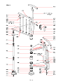
FIG. 1

51 - kl
FIG. 4
FIG. 5
FIG. 5 A
FIG. 6
FIG. 3FIG. 2

52 - kl
FIG. 7

53 - kl
FIG. 8
FIG. 9
FIG. 10 FIG. 11
FIG. 12

54 - kl

English
Français
Español
PRODUCT DETAILS
DONNÉES D’IDENTIFICATION DU PRODUIT
DATOS DE IDENTIFICACIÓN
La page est en cours de chargement...
La page est en cours de chargement...
La page est en cours de chargement...
La page est en cours de chargement...
La page est en cours de chargement...
-
 1
1
-
 2
2
-
 3
3
-
 4
4
-
 5
5
-
 6
6
-
 7
7
-
 8
8
-
 9
9
-
 10
10
-
 11
11
-
 12
12
-
 13
13
-
 14
14
-
 15
15
-
 16
16
-
 17
17
-
 18
18
-
 19
19
-
 20
20
-
 21
21
-
 22
22
-
 23
23
-
 24
24
-
 25
25


dans d''autres langues
- English: Arke K07088 Installation guide
- español: Arke K07088 Guía de instalación
Documents connexes
-
Arke K03071 Guide d'installation
-
-
-
-
-
 Fontanot 894168001296 Guide d'installation
-
-
-
Arke K35018 Guide d'installation
-