Kichler Lighting 49934WZC Manuel utilisateur
- Taper
- Manuel utilisateur

Date Issued: 10/13/17 IS-49934-CB
We’re here to help 866-558-5706
Hrs: M-F 9am to 5pm EST
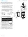
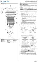
CAUTION – RISK OF SHOCK –
Disconnect Power at the main circuit breaker panel or main
fusebox before starting and during the installation.
3
5
4
2
7
1
6
7
8
9
10
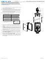
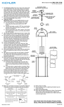
1) Slip xture over post and mark position of mounting holes in
post.
2) Remove xture from post.
3) Drill 3/16” dia holes in post at positions marked .
4) If xture is provided with ground wire, connect xture ground
wire to outlet box ground wire with wire connector. Never con-
nect ground wire to black or white power supply wires.
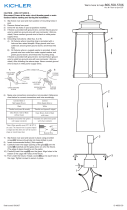
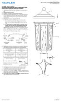
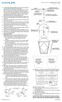
5) Grounding instructions: (See Illus. A or B).
A) On xtures where mounting strap is provided with a
hole and two raised dimples. Wrap ground wire from
outlet box around green ground screw, and thread into
hole.
B) On xtures where a cupped washer is provided. Attach
ground wire from outlet box under cupped washer and
green ground screw, and thread into mounting strap.
If xture is provided with ground wire. Connect xture ground
wire to outlet box ground wire with wire connector. (Not pro-
vided.) After following the above steps. Never connect ground
wire to black or white power supply wires.
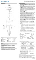
6) Make wire connections using wire nuts[7]. Reference chart
below for correct connections and wire accordingly.
7) Slip xture over post and secure in place using provided
screws[1]. Screws should slip into holes drilled in post.
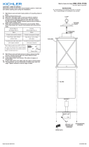
8) Install glass[4] by sliding down from the top of glass cage[2]
and seat into the inside bottom of cage as shown. Next bend
over the tabs above the glass to secure into place. Repeat for
all the glass panels.
9) Insert recommended bulb(s) (not supplied).
10) Take bracket assembly[9] and thread on to the glass cage
assembly[2] and and secure into place with the studded ball
knobs[10] as shown.
11) Place the top[3] onto the installed bracket assembly and se-
cure into place with the two hexnuts[8].
12) Place decorative ring[7] on top of main assembly. Next place
top ring[6] onto the decorative ring as shown and secure into
place using the open nial[5].
GREEN GROUND
SCREW
CUPPED
WASHER
OUTLET BOX
GROUND
FIXTURE
GROUND
DIMPLES
WIRE CONNECTOR
OUTLET BOX
GROUND
GREEN GROUND
SCREW
FIXTURE
GROUND
A
B
Connect Black or Red
Supply Wire to:
Connect White Supply Wire to:
Blac
kW
hite
*Parallel cord (round & smooth)
*Parallel cord (square & ridged)
Clear, Brown, Gold or Black
without Tracer
Clear, Brown, Gold or Black
with Tracer
Insulated wire (other than green)
with copper conductor
Insulated wire (other than green)
with silver conductor
*Note: When parallel wire (SPT I & SPT II)
are used. The neutral wire is square shaped or
ridged and the other wire will be round in
shape or smooth (see illus.)
Neutral Wire

Date Issued: 10/13/17 IS-49934-CB
INSTRUCTIONS
For Assembling and Installing Fixtures in Canada
Pour L’assemblage et L’installation Au Canada
Nous sommes là pour vous aider 866-558-5706
Heures : du lundi au vendredi, de 9h à 17h (heure de l’Est)
ATTENTION – RISQUE DE DÉCHARGES ÉLECTRIQUES -
Couper le courant au niveau du panneau du disjoncteur du
circuit principal ou de la boîte à fusibles principale avant de
procéder à l’installation.
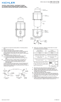
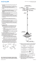
1) Passer le luminaire par dessus le support et marquer un repère
pour les trous de montage sur le support.
2) Enlever le luminaire du support.
3) Percer des trous de 1/8 po sur chacun des repères du support.
4) Siluminaireestfourniavecunldemiseàlaterre,lecon-
necteràlaboîtedesortiedecourantdemiseàlaterreavec
unserre-ls(nonfourni).Nejamaisconnecterunldemiseà
laterreauxlsd’alimentationnoiroublanc.
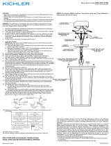
5) Connecterleslsutiliserdesécrous[7].Seporterautableau
ci-dessous pour faire les connexions.
6) Faireglisserleluminairesurlesupportetxeràl’aidedes
vis[1].Lesvisdoivents’ajustercorrectementdanslestrousdu
support.
7) Installez la vitre [4]englissantverslehautdepuislebasdela
cage[2]enverreetinsérez-ladanslefondintérieurdelacage,
commeindiqué.Ensuite,pliezleslanguettesau-dessusdu
verrepourlesxerenplace.Répétezl’opérationpourtousles
panneaux de verre.
8) Installerlaoulesampoulesrecommandées(nonfournies).
9) Prendrel’ensembledesupport[9]etlevissersurl’ensemble
de la cage de verre [2]etlexeraveclesboutonsdeboule
cloutés[10]commeindiqué.
10) Placez le dessus [3]surl’ensembledesupportinstalléetxez-
le en place avec les deux hexagones [8].
11)Placezlabaguedécorative[7]surledessusdel’assemblage
principal.Placezensuitelabaguesupérieure[6]surlabague
décorativecommeindiquéetxez-laenplaceàl’aidedueu-
ron ouvert [5].
3
5
4
2
7
1
6
7
8
9
10
Connecter le fil noir ou
rouge de la boite
Connecter le fil blanc de la boîte
A Noir A Blanc
*Au cordon parallèle (rond et lisse)
*Au cordon parallele (à angles droits el strié)
Au bransparent, doré, marron, ou
noir sans fil distinctif
Au transparent, doré, marron, ou
noir avec un til distinctif
Fil isolé (sauf fil vert) avec
conducteur en cuivre
Fil isolé (sauf fil vert) avec
conducteur en argent
*Remarque: Avec emploi d’un fil paralléle
(SPT I et SPT II). Le fil neutre est á angles
droits ou strié et l’autre fil doit étre rond ou
lisse (Voir le schéma).
Fil Neutre
-
 1
1
-
 2
2


Kichler Lighting 49934WZC Manuel utilisateur
- Taper
- Manuel utilisateur
dans d''autres langues
Documents connexes
-
 Kichler Lighting 49920BK Manuel utilisateur
-
 Kichler Lighting 49860BKT Manuel utilisateur
-
 Kichler Lighting 49941WZC Manuel utilisateur
-
 Kichler Lighting 49895OZ Manuel utilisateur
-
 Kichler Lighting 49236BSL Manuel utilisateur
-
 Kichler Lighting 49626BKTLED Manuel utilisateur
-
 Kichler Lighting 49718OZ Manuel utilisateur
-
 Kichler Lighting 43259DAW Manuel utilisateur
-
 Kichler Lighting 43201OZ Manuel utilisateur
-
 Kichler Lighting 49746WZCL18 Manuel utilisateur


