
Installation Instructions
instructions d'installation
Instrucciones de instalación


TABLE OF CONTENTS
RANGE SAFETY ...................................................................................................2
INSTALLATION REQUIREMENTS ......................................................................... 4
Tools and Parts ............................................................................................................... 4
Location Requirements .................................................................................................6
Electrical Requirements ................................................................................................9
Gas Supply Requirements ...........................................................................................10
INSTALLATION INSTRUCTIONS ........................................................................13
Step 1 - Unpack Range ................................................................................................13
Step 2 - Install Backsplash ...........................................................................................13
Step 3 - Install Anti-tip Bracket ...................................................................................15
Step 4 - Make Gas Connection ....................................................................................17
Step 5 - Make Electrical Connection ...........................................................................19
Step 6 - Install Range ...................................................................................................19
Step 7 - Level the Range (if needed) ..........................................................................21
Step 8 - Check Operation of Electronic Ignition System ...........................................21
GAS CONVERSION ............................................................................................ 22
Step 1 - Adjust the Regulator ......................................................................................25
.................................................................................26
Step 3 - Adjust Burner Flames ....................................................................................27
Step 4 - Testing Flame Stability ...................................................................................28
Step 5 - Flame Re-Check .............................................................................................28
1

RANGE SAFETY
Your safety and the safety of others are very important.
We have provided many important safety messages in this manual and
on your appliance. Always read and obey all safety messages.
DANGER
WARNING
CAUTION
This is the safety alert symbol.
This symbol alerts you to potential hazards that can
kill or hurt you and others. All safety messages will
follow the safety alert symbol and either the word
“DANGER,” “WARNING” or “CAUTION.”
These words mean:
An imminently hazardous situation. You
could be killed or seriously injured if you
don’t immediately follow instructions.
A potentially hazardous situation
which, if not avoided, could result in
death or serious bodily injury.
A potentially hazardous situation
which, if not avoided, may result in
moderate or minor injury.
All safety messages will tell you what the potential hazard is, tell you
how to reduce the chance of injury, and tell you what can happen if the
instructions are not followed.
2

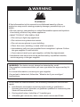
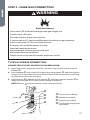
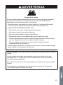
WARNING
Fire Hazard
If the information in this manual is not followed exactly, a fire or
explosion may result causing property damage, personal injury or
death.
- Do not store or use gasoline or other flammable vapors and liquids in
the vicinity of this or any other appliance.
- WHAT TO DO IF YOU SMELL GAS
• Do not try to light any appliance.
• Do not touch any electrical switch.
• Do not use any phone in your building.
• Clear the room, building, or area of all occupants.
• Immediately call your gas supplier from a neighbor’s phone. Follow
the gas supplier’s instructions.
• If you cannot reach your gas supplier, call the fire department.
- Installation and service must be performed by a qualified installer,
service agency or the gas supplier.
WARNING: Gas leaks cannot always be detected by smell.
Gas suppliers recommend that you use a gas detector approved by UL
or CSA.
For more information, contact your gas supplier.
If a gas leak is detected, follow the “What to do if you smell gas”
instructions.
In the State of Massachusetts, the following installation instructions
apply:
•
State of Massachusetts.
•
If using a ball valve, it shall be a T-handle type.
•
3

State of California Proposition 65 Warnings:
WARNING: This product contains one or more chemicals known to the
State of California to cause cancer.
WARNING: This product contains one or more chemicals known to the
State of California to cause birth defects or other reproductive harm.
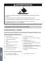
WARNING
Tip Over Hazard
A child or adult can tip the range and be killed.
Connect anti-tip bracket to rear range foot.
Reconnect the anti-tip bracket, if the range is moved.
Failure to follow these instructions can result in death or serious burns
to children and adults.
INSTALLATION REQUIREMENTS
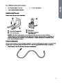
TOOLS AND PARTS
Gather the required tools and parts before starting installation. Read and follow the
instructions provided with any tools listed here.
TOOLS NEEDED
•
Tape measure
•
Flat-blade screwdriver
•
Phillips screwdriver
•
Level
•
Cordless electric drill
•
Hammer
•
Wrench or pliers
•
Pipe wrench
•
10" Adjustable Wrenches (2)
•
•
¼" nut driver
•
•
Marker or pencil
•
Masking tape
•
Pipe-joint compound resistant to LP gas
•
•
Noncorrosive leak-detection solution
4

5

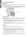
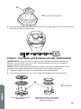
LOCATION REQUIREMENTS
VENTILATION
IMPORTANT:
combustion and ventilation air.
•
on the model/serial rating plate. The model/serial rating plate is located on the
left-hand side of the oven frame. Open oven door to view label. See label on back
panel of range for additional element and oven power ratings.
a
a Rating Plate
TEMPERATURE
IMPORTANT: This oven has been designed in accordance with the requirements of
temperatures of 194F (90°C).
•
Some cabinet and building materials are not designed to withstand the heat
produced by the oven for baking and self-cleaning. Check with your builder
or cabinet supplier to make sure that the materials used will not discolor,
delaminate or sustain other damage.
•
withstand at least 200°F (93°C).
•
Use an insulated pad or ¼" (0.64 cm) plywood under range if installing range over
carpeting.
GENERAL
•
The range should be located for convenient use in the kitchen.
•
Recessed installations must provide complete enclosure of the sides and rear of
the range.
•
cabinet storage space located above the surface units should be avoided. If
cabinet storage is to be provided, the risk can be reduced by installing a range
hood or microwave hood combination that projects horizontally a minimum of 5"
(12.7 cm) beyond the bottom of the cabinets.
•
•
Do not seal the range to the side cabinets.
•
Grounded electrical supply is required. See “Electrical Requirements” section.
•
Proper gas supply connection must be available. See “Gas Supply Requirements”
section.
6

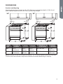
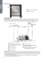
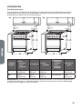
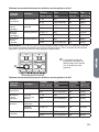
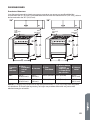
DIMENSIONS
Product and Opening
Opening dimensions shown are for 25" (64.0 cm) countertop depth, 4" (61.0 cm)
base cabinet depth and 36" (91.4 cm) countertop height.
30"
(76 cm)
Min.
5.9"
(15 cm)
Min.
b
d
c
e
24"
a
30"
(76 cm)
Min.
5.9"
(15 cm)
Min.
b
d
c
e
36"
a
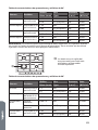
Model
Size
A. Depth w/
Handle
B. Width C. Depth
D. Height to top
of Cooktop
E. Height
Overall
24"
36" (91 cm)
36"
36" (91 cm)
NOTE:
7

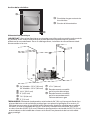
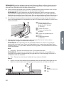
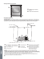
Back of Range
b
a
a Gas Line from Range
b Power Cord
Power Supply
IMPORTANT:
mounted, but an electrical outlet in the wall must be recessed to make the
a
b
e
d
g
h
c
f
a
b 11½" (29.2 cm)
c 6" (15.2 cm)
d 7¼" (18.4 cm)
e 3" (7.6 cm)
f 17½" (44 cm)
g Recommended Location for
Electrical Outlet
h Recommended Location for
Gas Supply Connection
* NOTE: 24" (61.0 cm) minimum when bottom of wood or metal cabinet is covered
No. 28 MSG sheet steel, 0.015" (0.4 mm) stainless steel, 0.024" (0.6 mm) aluminum
or 0.020" (0.5 mm) copper.
30" (76.2 cm) minimum clearance between the cooking and the bottom of an
uncovered wood or metal cabinet.
8

ELECTRICAL REQUIREMENTS
WARNING
Electrical Shock Hazard
Plug into a grounded 3 prong outlet.
Do not remove the ground prong from the power cord plug.
Do not use an adapter.
Do not use an extension cord.
Failure to do so can result in death, fire or electrical shock.
IMPORTANT: The range must be electrically grounded in accordance with local
codes and ordinances, or in the absence of local codes, with the National Electrical
Code, ANSI/NFPA 70 or Canadian Electrical Code, CSA C22.1.
This range is equipped with an electronic ignition system that will not operate if
plugged into an outlet that is not properly polarized.
If codes permit and a separate ground wire is used, it is recommended that a
A copy of the above code standards can be obtained from:
National Fire Protection Association
1 Batterymarch Park
Quincy, MA 02169-7471
CSA International
8501 East Pleasant Valley Road
Cleveland, OH 44131-5575
•
A 120 volt, 60 Hz., AC only, 15-amp fused, electrical circuit is required. A time-
delay fuse or circuit breaker is also recommended. It is recommended that a
separate circuit serving only this range be provided.
•
Electronic ignition systems operate within wide voltage limits, but proper
grounding and polarity are necessary. Check that the outlet provides 120-volt
power and is correctly grounded.
•
This gas range is not required to be plugged into a GFCI (Ground-Fault Circuit
Interrupter) outlet. It is recommended that you not plug an electric spark
ignition gas range or any other major appliance into a GFCI wall outlet as it may
cause the GFCI to trip during normal cycling.
•
circuit. However, occasional nuisance tripping of the GFCI breaker is possible
due to the normal operating nature of electronic gas ranges.
•
The wiring diagram is located on the back of the range in a clear plastic bag.
9

NOTE: The metal chassis of the range must be grounded in order for the control
panel to work. If the metal chassis of the range is not grounded, no keypads will
metal chassis of the range is grounded.
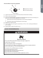
GAS SUPPLY REQUIREMENTS
WARNING
Explosion Hazard
Use a new CSA International approved gas supply line.
Install a shut-off valve.
Securely tighten all gas connections.
If connected to LP, have a qualified person make sure gas pressure
does not exceed 14" (36 cm) water column.
Examples of a qualified person include:
licensed heating personnel,
authorized gas company personnel, and
authorized service personnel.
Failure to do so can result in death, explosion or fire.
Observe all governing codes and ordinances.
IMPORTANT: This installation must conform with all local codes and ordinances.
In the absence of local codes, installation must conform with American National
Standard, National Fuel Gas Code ANSI Z223.1 - latest edition or CAN/CGA B149 –
latest edition.
IMPORTANT: Leak testing of the range must be conducted according to the
manufacturers instructions.
TYPE OF GAS
Natural gas:
proper conversion, for use with LP gas.
•
This range is factory set for use with Natural gas. See “Gas Conversions”
section. The model/serial rating plate located on the right side oven door trim
has information on the types of gas that can be used. If the types of gas listed do
not include the type of gas available, check with the local gas supplier.
10

LP gas conversion:
IMPORTANT:
LP Conversion kit for this product is sold separately.
gas supplier. See “Gas Conversions” section.
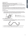
GAS SUPPLY LINE
Provide a gas supply line of ¾" (1.9 cm) rigid pipe to the range location. A smaller size
resist the action of LP gas must be used. With LP gas, piping or tubing size can be ½"
(1.3 cm) minimum. Usually, LP gas suppliers determine the size and materials used in
the system.
Gas Shut-o Valve:
•
a b c
a Gas Supply Line
b
c
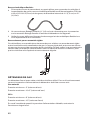
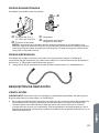
Flexible metal appliance connector:
•
for connecting range to the gas supply line.
•
A ½" (1.3 cm) male pipe thread is needed for connection to the female pipe
threads of the inlet to the appliance pressure regulator.
•
11

Rigid pipe connection:
connection to the range. The rigid pipe must be level with the range connection. All
strains must be removed from the supply and fuel lines so range will be level and in
line.
GAS PRESSURE REGULATOR
The gas pressure regulator supplied with this range must be used. The inlet pressure
to the regulator should be as follows for proper operation:
Natural gas:
Minimum pressure: 5" Water Column Pressure (WCP)
LP gas:
Minimum pressure: 8" WCP
Contact local gas supplier if you are not sure about the inlet pressure.
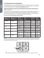
Burner Input Requirements
Input ratings shown on the model/serial rating plate are for elevations up to 2,000 ft
(609.6 m).
For elevations above 2,000 ft (609.6 m), ratings are reduced at a rate of 4% for each
1,000 ft (304.8 m) above sea level (not applicable for Canada).
GAS SUPPLY PRESSURE TESTING
Gas supply pressure for testing regulator must be at least 1" Water Column Pressure
(WCP) above the manifold pressure shown on the model/serial rating plate.
Line pressure testing above 0.5 psi gauge (14" WCP)
of 0.5 psi (3.5 kPa).
Line pressure testing at 0.5 psi gauge (14" WCP) or lower
The range must be isolated from the gas supply piping system by closing its
system at test pressures equal to or less than 0.5 psi (3.5 kPa).
12

INSTALLATION INSTRUCTIONS
IMPORTANT: This appliance shall be installed only by authorized persons and
regulations, municipal building codes, electrical wiring regulations, local water
supply regulations.
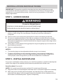
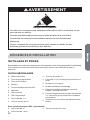
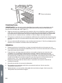
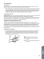
STEP 1 - UNPACK RANGE
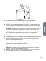
WARNING
Excessive Weight Hazard
Use two or more people to move and install range.
Failure to do so can result in back or other injury.
1.
bottom under range. Do not dispose of anything until the installation is
complete.
2. Remove oven racks and parts package from oven and shipping materials.
3.
Stack one cardboard corner on top of another. Repeat with the other 2 corners.
it is laid on its back.
4.
the cardboard corners.
5. Remove cardboard bottom.
NOTES:
•
The leveling legs can be adjusted while the range is on its back.
•
To place range back up into a standing position, put a sheet of cardboard or
more people, stand range back up onto the cardboard or hardboard.
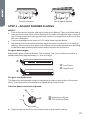
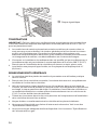
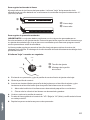
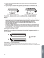
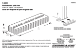
STEP 2 - INSTALL BACKSPLASH
For proper ventilation and to protect your wall from splatters, install the backsplash
Parts Provided: Screws (6)
NOTE: 24" model uses (4) screws and the 36" model uses (6) screws
1. Align the holes in the backsplash with the holes in the back edge of the cooktop.
2. With one person holding the backsplash, and working from underneath the
the bottom of the backsplash. Tighten completely.
13

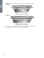
NOTE: 24" model uses (2) screws and the 36" model uses (4) screws
24" Model
a
b
a Backsplash -Back Edge
b Backsplash - Bottom Edge
36" Model
a
b
a Backsplash -Back Edge
b Backsplash - Bottom Edge
3. Insert the two screws (one on each side) through the back edge of the
backsplash and into the cooktop. Tighten completely.
14

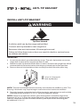
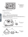
STEP 3 - INSTALL ANTI-TIP BRACKET
INSTALL ANTI-TIP BRACKET
WARNING
Tip Over Hazard
A child or adult can tip the range and be killed.
Connect anti-tip bracket to rear range foot.
Reconnect the anti-tip bracket, if the range is moved.
Failure to follow these instructions can result in death or serious burns
to children and adults.
IMPORTANT:
•
An anti-tip bracket is provided with the range. The anti-tip bracket uses a rear
range foot to secure the range to the oor or wall.
•
Attach the anti-tip bracket to the oor or wall so that the rear range foot will be
centered within the bracket when the range is pushed into its nal position.
1. Remove the anti-tip bracket and two screws (provided) from the parts bag.
a
b
a 16 x 1⁵⁄₈" Screws (2)
b Anti-tip Bracket
NOTE: The anti-tip bracket must be securely mounted to the suboor or wall. The
ooring’s thickness may require longer screws to anchor bracket to suboor.
2. Place the bracket so that the back of the bracket is against the rear wall and the
side edge of the bracket is ³⁄₈" to ¹⁄₂" from the adjacent cabinet.
NOTE: If there is no adjacent cabinet, place the bracket so that the edge of the
br
acket is ³⁄₈" to ¹⁄₂" in from the range side panel. If the countertop overhangs the
cabinet, oset the bracket from the cabinet by the depth of the overhang plus
an additional ³⁄₈" to ¹⁄₂".
15

3. Using the anti-tip bracket as a template, mark the two holes for either a Floor
Wood, Floor Concrete, or Wall installation, as shown.
a
b
c
d
e
a Distance from
Adjacent Cabinet (³⁄₈"
to ¹⁄₂" [0.95 to 1.27 cm])
b Wall Holes
c Concrete Floor Holes
d Wood Floor Holes
e Rear Range Foot
4. Drill two pilot holes where marked. Follow the instructions specic to your
construction.
NOTE: A nail or awl may be used to create a pilot hole, if a drill is not available.
For concrete construction ¹⁄₄" x 1¹⁄₂" Lag Bolts and ¹⁄₂" O.D. Sleeve Anchors are
required.
Wood
•
Floor - Drill a ¹⁄₈" pilot hole, as shown.
NOTE: Contact a qualied oor covering installer for the best procedure for
drilling mounting holes through your type of oor covering.
•
Wall - Drill an angled ¹⁄₈" pilot hole, as shown.
Concrete
•
Drill the size hole recommended for the anchors into the concrete at the
center of the holes identied as Floor Concrete or Wall.
a
b
c
a Wall
b Anti-tip
Bracket
c Floor
5. Install the anti-tip bracket.
Wood
•
Using the two screws (provided) fasten the anti-tip bracket to the oor or
wall.
NOTE: The screw must enter wood or metal.
Concrete
•
Insert the sleeve anchor into the drilled holes and then insert the lag bolts
through the anti-tip bracket and into the oor or wall. The bolts must be
properly tightened as recommended for the hardware.
6. Complete the range installation following the Installation Instructions
(provided).
16

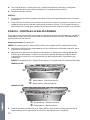
STEP 4 - MAKE GAS CONNECTION
WARNING
Explosion Hazard
Use a new CSA International approved gas supply line.
Install a shut-off valve.
Securely tighten all gas connections.
If connected to LP, have a qualified person make sure gas pressure
does not exceed 14" (36 cm) water column.
Examples of a qualified person include:
licensed heating personnel,
authorized gas company personnel, and
authorized service personnel.
Failure to do so can result in death, explosion or fire.
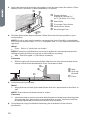
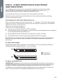
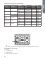
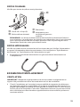
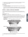
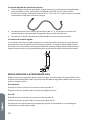
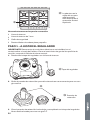
TYPICAL FLEXIBLE CONNECTION
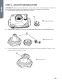
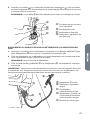
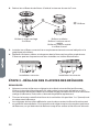
CONNECT BSPP TO NPT ADAPTER TO GAS REGULATOR:
1. Apply pipe-joint compound made for use with LP gas to the male threads of
adapter
c
.
2. Insert adapter
c
into outlet of the gas pressure regulator
d
, and then tighten
up toward the range gas inlet pipe.
3. Install washer
b
in female end of adapter
c
, and then connect adapter
c
to
range gas inlet pipe
a
NOTE: Washer
b
must be used to create a leak proof seal.
a
b
c
d
a Gas Line from Range
b Washer (provided)
c Adapter (provided)
d Gas Pressure Regulator
(provided)
17

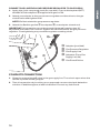
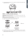
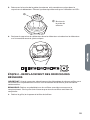
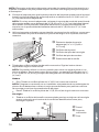
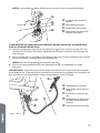
CONNECT GAS LINE FROM GAS PRESSURE REGULATOR TO GAS SUPPLY:
1. Apply pipe-joint compound made for use with LP gas to the tapered (NPT)
threads of both adapters
d
supplied with gas line kit.
2. Attach one adapter to the gas pressure regulator and the other to the gas
NOTE: Do Not rotate the gas pressure regulator.
3.
c
to adapters
d
, one adapter at each end.
IMPORTANT: All connections must be wrench tightened (requires two 10"
adjustable wrenches). Do not over-tighten the connections to the gas pressure
regulator. Overtightening may crack the regulator creating a leak.
b
c
e
a
d
d
a Adapter (provided)
b Gas Pressure Regulator
c Gas Supply Line
d Adapters (From Gas
Supply Line Kit)
e
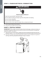
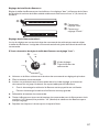
COMPLETE CONNECTION
1.
handle is parallel to the gas pipe.
2. Test all connections by brushing on an approved noncorrosive leak-detection
solution. If bubbles appear, a leak is indicated. Correct any leak found.
18
La page est en cours de chargement...
La page est en cours de chargement...
La page est en cours de chargement...
La page est en cours de chargement...
La page est en cours de chargement...
La page est en cours de chargement...
La page est en cours de chargement...
La page est en cours de chargement...
La page est en cours de chargement...
La page est en cours de chargement...
La page est en cours de chargement...
La page est en cours de chargement...
La page est en cours de chargement...
La page est en cours de chargement...
La page est en cours de chargement...
La page est en cours de chargement...
La page est en cours de chargement...
La page est en cours de chargement...
La page est en cours de chargement...
La page est en cours de chargement...
La page est en cours de chargement...
La page est en cours de chargement...
La page est en cours de chargement...
La page est en cours de chargement...
La page est en cours de chargement...
La page est en cours de chargement...
La page est en cours de chargement...
La page est en cours de chargement...
La page est en cours de chargement...
La page est en cours de chargement...
La page est en cours de chargement...
La page est en cours de chargement...
La page est en cours de chargement...
La page est en cours de chargement...
La page est en cours de chargement...
La page est en cours de chargement...
La page est en cours de chargement...
La page est en cours de chargement...
La page est en cours de chargement...
La page est en cours de chargement...
La page est en cours de chargement...
La page est en cours de chargement...
La page est en cours de chargement...
La page est en cours de chargement...
La page est en cours de chargement...
La page est en cours de chargement...
La page est en cours de chargement...
La page est en cours de chargement...
La page est en cours de chargement...
La page est en cours de chargement...
La page est en cours de chargement...
La page est en cours de chargement...
La page est en cours de chargement...
La page est en cours de chargement...
La page est en cours de chargement...
La page est en cours de chargement...
La page est en cours de chargement...
La page est en cours de chargement...
La page est en cours de chargement...
La page est en cours de chargement...
La page est en cours de chargement...
La page est en cours de chargement...
La page est en cours de chargement...
La page est en cours de chargement...
La page est en cours de chargement...
La page est en cours de chargement...
La page est en cours de chargement...
La page est en cours de chargement...
La page est en cours de chargement...
La page est en cours de chargement...
La page est en cours de chargement...
-
 1
1
-
 2
2
-
 3
3
-
 4
4
-
 5
5
-
 6
6
-
 7
7
-
 8
8
-
 9
9
-
 10
10
-
 11
11
-
 12
12
-
 13
13
-
 14
14
-
 15
15
-
 16
16
-
 17
17
-
 18
18
-
 19
19
-
 20
20
-
 21
21
-
 22
22
-
 23
23
-
 24
24
-
 25
25
-
 26
26
-
 27
27
-
 28
28
-
 29
29
-
 30
30
-
 31
31
-
 32
32
-
 33
33
-
 34
34
-
 35
35
-
 36
36
-
 37
37
-
 38
38
-
 39
39
-
 40
40
-
 41
41
-
 42
42
-
 43
43
-
 44
44
-
 45
45
-
 46
46
-
 47
47
-
 48
48
-
 49
49
-
 50
50
-
 51
51
-
 52
52
-
 53
53
-
 54
54
-
 55
55
-
 56
56
-
 57
57
-
 58
58
-
 59
59
-
 60
60
-
 61
61
-
 62
62
-
 63
63
-
 64
64
-
 65
65
-
 66
66
-
 67
67
-
 68
68
-
 69
69
-
 70
70
-
 71
71
-
 72
72
-
 73
73
-
 74
74
-
 75
75
-
 76
76
-
 77
77
-
 78
78
-
 79
79
-
 80
80
-
 81
81
-
 82
82
-
 83
83
-
 84
84
-
 85
85
-
 86
86
-
 87
87
-
 88
88
-
 89
89
-
 90
90
-
 91
91


Cosmo COS-965AGC Manuel utilisateur
- Taper
- Manuel utilisateur
- Ce manuel convient également à
dans d''autres langues
- English: Cosmo COS-965AGC User manual
- español: Cosmo COS-965AGC Manual de usuario
Autres documents
-
Haier HCR6250AGS Guide d'installation
-
-
-
Jenn-Air Range W10394575A Manuel utilisateur
-
Jenn-Air JDRP548WP01 Guide d'installation
-
KitchenAid KFDD500ESS Guide d'installation
-
-
Jenn-Air KSDB900ESS Guide d'installation
-
 Prime-Line N 6900 Guide d'installation
