Andersen Single Retractabe Insect Screen Mode d'emploi
- Taper
- Mode d'emploi

· Product Series - 200 Series, 400 Series, A-Series, E-Series
· Product Type - Gliding Patio Doors
· Panel Operation - 2-Panel and 3-Panel
INSTALLATION 9205707 BA 01/12/2024
Single Retractable Insect Screen
Installation Instructions for:
“Andersen” and all other marks where denoted are trademarks of the Andersen Corporation. ©2024 Andersen Corporation. All rights reserved.
Stationary-Active Active-Stationary Active-Stationary-Active
Read these instructions
and the Product Safety
Information before
starting procedure.
Please Do Not Return Product to Store!
· Call the Andersen Help Line at -
888-888-7020
with any questions regarding installation, lost part replacement,
or anything else related to your Retractable Insect Screen purchase.
IMPORTANT
Tools Needed
Protective
Gloves
Drill/
Driver
Rubber
Mallet
Safety
Glasses
Laser
Level
#2 Phillips
Screwdriver
1/8"
Drill Bit
Tape
Measure
Wood
Block
Level
Punch
Clamp Tape
Head Track
Retainer
Retractable
Insect Screen
Assembly
Sill
Adaptor
Sill Adaptor
Cover
Latch
Housing
Retainer
· Follow the color coded sections
in each step for your specic door
series. Failure to do so could result
in product or property damage.
NOTICE
A-SeriesA-Series
E-SeriesE-Series
200/400
Series
Parts Included:
- Retractable Insect
Screen Assembly
- Head Track Retainer
- Latch Housing Retainer
- Sill Adaptor
- Sill Adaptor Cover
(200/400 Series, E-Series Only)
- Screw Pack
- Clear Sealant
- Installation Instructions
- Important Product
and Safety Information
- Warranty
SDD p/n 903936
Left Handed
Door shown
Caulking
Gun
Pencil

2
9205707
#8 x 3/8"
Phillips Pan Head Screw
QUANTITY
#8 x 3/8"
Phillips Pan Head Screw
#8 x 3/8"
Phillips Round Head Screw
#8 x 3/4"
Phillips Round Head Screw
#8 x 2" Phillips
Pan Head Screw
1 Pair
1 Pair
2
2
--
3
--
--
1 Pair
1 Pair
9
2
3
--
--
--
1 Pair
1 Pair
2
2
3
--
4
3
SCREW PACK CONTENTS (Fasteners shown full size)
Finish
Black
--
--
Black
--
--
--
--
Material
Stainless
Steel
Stainless
Steel
Stainless
Steel
Stainless
Steel
Stainless
Steel
Stainless
Steel
Stainless
Steel
Stainless
Steel
Type
Spring
Tension
Spring
Tension
Self-
Drilling
Self-
Drilling
Thread-
Forming
Standard
Thread-
Forming
Standard
Description
Mounting
Brackets
A-Series E-Series
200/400
Series A-SeriesA-Series E-SeriesE-Series
200/400
Series
#8 x 3/4"
Phillips Pan Head Screw
This area intentionally left blank.
The retractable insect screen is intended for reasonable insect control and not the retention of objects, persons, or pets within the
interior. The retractable insect screen will not stop a person from falling through the door.
IMPORTANT

3
DraftDraft
1
Procedure and
Product Information
IMPORTANT
Important Safety and
Product Information
for Andersen® Windows and Doors
This is the Safety Alert Symbol used to alert you to
potential injury hazards. Obey all safety messages that
follow this symbol to avoid possible injury or death.
Signal Word and Consequence
Major Injury/Death
WARNING
COULD
Result in: Minor Injury
CAUTION
COULD
Result in:
Product or Property
Damage
NOTICE
COULD
Result in:
· Leave this installation instruction with the home/building owner.
· For additional support or help please go to: andersenwindows.com and visit our Help Center.
· To congure installation instructions go to: andersenwindows.com/installation
Handling Installation
· Use caution when working at elevated heights and
around window and door openings. Follow the
manufacturers’ instructions for ladders and scaffolding.
Failure to do so could result in injury or death.
· Support window or door in opening at all times until
fully fastened. Failure to do so could result in window or
door falling out causing injury, property or product
damage.
· Windows and doors have small parts (e.g. hole plugs,
operator spline caps, fasteners, etc.). Small parts if
swallowed could pose a choking hazard to young
children. Dispose of unused, loose, or easily removed
small parts. Failure to do so could result in injury.
· Protect surfaces from tool contact. Failure to do so
could result in injury, product damage, or surface
marring.
· Windows and doors can be heavy. Use safe lifting
techniques and a reasonable number of people with
enough strength to lift, carry, and install window and
door products. Heavier windows and doors will require
mechanical assistance. Failure to do so could result in
injury, product or property damage.
· DO NOT lift or carry window or door by the exterior
trim, extension jambs, hardware, or accessories. Doing
so could result in injury, product or property damage.
· Windows, doors, and installation components can
have sharp edges. Wear protective equipment when
handling. Failure to do so could result in injury.
· DO NOT drag, rock, cartwheel, or walk windows,
doors, sash, or panels across the floor. Doing so could
result in product or property damage.
Tools
· Follow manufacturers’ instructions for hand and power tools. Always wear safety glasses. Failure to do so could result in
injury, product or property damage.
❚ Tools
❚ Handling
❚ Installation
❚ Sealing
❚ Fastening
❚ Finishing
Safety and Product Information Index
❚ Glass
❚ Protective Film
❚ Cleaning
❚ Use/Operation
❚ Joining
❚ Product Information
Read this Important Safety and Product
Information completely before starting.
WARNING
WARNING WARNING
“Andersen” and all other marks where denoted are trademarks of Andersen Corporation. ©2023 Andersen Corporation. All rights reserved. SAFETY/PRODUCT INFORMATION 9144348 BH Revised 08/01/2023

4
DraftDraft
2
NOTICE
· Andersen head ashing and installation anges DO
NOT take the place of window and door ashing tape or
liquid ashing. Window or door must be properly ashed
and sealed with a material compatible sealant for
protection against water and air inltration.
Failure to do
so could result in product or property damage.
· DO NOT set window or door directly on installation
ange. Doing so could affect product performance, and
could result in product or property damage.
· DO NOT set window directly on sill plate. Elevate
window with shims under the side jambs. Failure to do
so could affect operation and product performance, and
could result in product damage.
· Window or door must be properly shimmed. Failure to
do so could affect operation and product performance,
and could result in product damage.
· A continuous full perimeter interior seal between
window or door frame and opening is required. Failure to
do so will affect product performance, and could result
in product or property damage.
· Protect window and door sills during installation and
throughout construction. Failure to do so could result in
product damage.
· DO NOT remove window or door packaging material until
instructed to do so. Doing so could result in product damage.
Installation (Continued)
NOTICE
· Use masonry screws when fastening directly into
masonry or through a buck into masonry. Failure to do
so could affect product performance, and could result in
product or property damage.
· DO NOT over drive screws or nails. Doing so could
result in product damage.
· Fasteners must be attached to a structural framing
member. Failure to do so will reduce the structural
performance to less than published values and could
affect product performance, and could result in product
or property damage.
Fastening
· Metal fasteners and components could corrode when
exposed to preservative-treated or fire-retardant treated
lumber. Use approved fasteners and components to
fasten window or door. Failure to do so could cause a
failure resulting in injury, product or property damage.
· Fastener must attach to a structural framing member
with a 1-1/2" minimum fastener embedment. Failure to
do so could result in injury, product or property damage.
· DO NOT remove screws that attach installation clips or
gusset plates to window or door frames. Doing so could
result in injury, product or property damage.
Sealing
NOTICE
CAUTION
· Follow instructions of foam, sealant, and flashing
manufacturers regarding safety, material application,
compatibility, and periodic maintenance for continued
weather resistance of their products. Failure to do so
could result in injury, product or property damage.
Finishing
NOTICE
· DO NOT stain or paint weatherstrip, vinyl, glass, or
hardware. Doing so could result in product damage.
· Read and follow nish manufacturer's instructions and
safety information. Failure to do so could result in
product damage.
· DO NOT over load brush with stain or paint when
nishing. Doing so could allow nish to wick between
glass stop or grille, and glass.
WARNING
· Clean and prepare surfaces receiving sealant following
sealant manufacturer's instructions. Failure to do so could
result in water inltration causing product or property damage.
· DO NOT use abrasive cleaners or solvents when
cleaning Fibrex® material. Doing so could result in
product damage. Go to andersenwindows.com for a list
of recommended cleaners.

5
DraftDraft
3
NOTICE
Glass
· Unless specifically ordered, Andersen windows are not
equipped with safety glass, and if broken, could
fragment causing injury. Many laws and building codes
require safety glass in locations adjacent to or near
doors. Andersen windows are available with safety glass
that could reduce the likelihood of injury when broken.
Information on safety glass is available from your local
Andersen dealer.
· Tempered or laminated safety glass is not standard for
windows and must be special ordered. Check local
building codes for required locations. Failure to do so
could result in injury, product or property damage.
· DO NOT place suction grips over film
seams on glass. Suction grips will not
hold if placed over lm seam to lift or
move window or door. Window or door
will fall and could result in injury,
product or property damage.
· DO NOT remove any
protective film near
flammable materials.
Static charge created
when removing film
can ignite flammable
materials or cause a
shock. Doing so could result in injury, product or
property damage. See warning label on glass.
· Dispose of protective film immediately after
removing. Failure to do so could pose a suffocation
hazard to children.
NOTICE
· DO NOT remove protective lm from glass until after
construction is completed. Doing so could allow glass to
be damaged.
· Remove protective film from non-glass components
immediately after installation. Failure to do so could
result in product damage.
NOTICE
Cleaning
Protective FilmFinishing (Continued)
· Finish all wood surfaces immediately after
installation. Unnished wood will deteriorate, discolor,
and could bow or split. Some
surfaces are hidden from view.
· Some products are shipped
unassembled, and it may be
more convenient to finish
wood surfaces for these
products prior to
assembly and
installation.
WARNING
WARNING
· Acid solutions used for cleaning masonry or concrete
will damage all components of window or doors. Protect
window or door and follow cleaning product
manufacturer's instructions. If acid contacts window or
door, wash all surfaces immediately with clean water.
· DO NOT use or apply solvents, abrasives, harsh
chemicals or cleaners to window or door components.
Doing so will result in product damage.
For a list of recommended cleaners go
to: andersenwindows.com
· DO NOT use metal razor blades to
clean glass surface. Glass damage
could result.
· DO NOT apply any type of film to insulating glass.
Doing so could cause thermal stress conditions and
result in glass damage. Shading devices (e.g. insulated
coverings, shutters, etc.) could also cause thermal
stress and condensation causing deterioration of
windows or doors.
· DO NOT use sealants on exterior or
interior glass surface.
NOTICE

6
DraftDraft
4
Joining
IMPORTANT
· Buildings constructed prior to 1978 could contain lead
paint which could be disturbed during window or door
replacement. For more information on proper management
of lead paint, go to: www.epa.gov/lead
· Instructions may not be right for all installations due to
building design, construction materials, or methods used
and/or building or site conditions. Consult a contractor or
architect for recommendations.
· Installation flanges may need to be removed for some
installations. (e.g. masonry, replacement), or where exterior
finish is already applied (e.g. siding, brick veneer, stucco).
· Installation ange on the window or door alone will not
properly ash and seal the window or door.
· DO NOT remove band, plastic ties, or packing clips from
window or door until instructed.
· DO NOT remove performance (NFRC) label until after nal
inspection. Doing so could delay nal inspection and
sign-off by the code ofcial.
· Check with your local building code ofcial to identify and
conrm compliance with local building code requirements.
· Contact local authorities or waste management company
for proper recycling and disposal instructions for removed
window or door.
· For cleaning instructions for window and door components
go to: andersenwindows.com.
· During construction protect products from construction
debris, harsh chemical such as brick wash, roof runoff, and
cement/masonry which can cause damage to window and
door products.
· Protective lm is not present on all windows or doors.
Protective lm is not a substitute for masking.
· Remove protective film from glass within six (6) months of
installation and when temperature is above 32° F.
· Remove protective lm by peeling from seam or corner.
Use a plastic scraper to start if needed.
· Extension jambs can be factory applied on some windows
or eld applied prior to installation. DO NOT apply extension
jambs prior to window or door installation that will be
fastened with installation clips. Doing so could prevent
access to installation clips for fastening.
· For extension jamb application refer to
instructions included with part(s) or go to:
andersenwindows.com
· Use painters masking tape for protecting
products during construction. Avoid using
duct or packaging tapes.
Use/Operation
· DO NOT stand in front of or near windows or doors
during a storm. Doing so could result in injury.
Accessories such as grilles, art glass, and insect
screens could dislodge and become airborne if window
or door is impacted by wind-borne debris from severe
storms or hurricane strength winds. In the event of a
storm, remove all accessories from windows or doors
and move to a safe location.
· DO NOT install air conditioner in
window. Doing so could result in
injury, product or property damage.
· Wind load brackets
must be flipped out
when not tilting or
cleaning. If wind load
brackets are not flipped
out, window could blow
in resulting in potential
injury and/or product
damage.
· DO NOT attach objects or accessories to window or
door except Andersen® products specifically designed
for the window or door. Doing so could result in injury,
product or property damage.
Product and General Information
· DO NOT join any window or door, horizontally or
vertically, to any window or door not designed for
joining. Doing so could result in injury, product or
property damage.
· Joined windows or doors must be individually
supported in the opening. Failure to do so could affect
operation and product performance, and could result in
product or property damage.
CAUTION
WARNING
WARNING
Flipped Out Flipped In

7
9205707
)1
5th
1st Position Sill Adaptor
on gliding patio
door sill.
3rd
Reposition Sill
Adaptor.
4th
· Verify Patio Door is plumb, level,
and square. Correct as needed until
measurements are within 1/8".
IMPORTANT
Sill
Adaptor
Slide tighttight
to Side
Jamb.
· Protect surfaces from tool contact. Failure to do so
could result in surface marring or product damage.
NOTICE
· Only drill through rst wall of component
part, typically about 1/8". Failure to do so
could result in product or property damage.
NOTICE
2nd
Mark hole locations
on gliding patio
door sill then
remove Sill
Adaptor.
#8 x 3/8"
Stainless
Steel Thread-Forming Screw
200/400
Series
Position Sill Adaptor on patio door sill and slide tight to side jamb. Mark hole
locations, drill 1/8" holes through the rst sill wall ONLY, clear debris, reposition Sill Adaptor,
apply sealant in holes, and fasten with #8 x 3/8" Stainless Steel Thread-Forming Screws. DO NOT overtighten screws.
Apply sealant in holes and
fasten Sill Adaptor
with #8 x 3/8"
Stainless Steel
Thread-Forming
Screws.
Drill 1/8" holes through
gliding patio door sill at
marked hole locations
(rst wall ONLY).
· DO NOT overtighten
screws. Doing so could
result in product damage.
NOTICE

8
9205707
)1(continued)
1st
Position Sill Adaptor
on gliding patio
door sill.
5th
Drill 1/8" holes
through gliding
patio door sill
at marked hole
locations (rst
wall ONLY).
3rd
4th
Reposition Sill
Adaptor.
Sill
Adaptor
Slide tighttight
to Side
Jamb. · Only drill through rst wall of
component part, typically about
1/8". Failure to do so could result
in product or property damage.
NOTICE
· Protect surfaces
from tool contact.
Failure to do so
could result in
surface marring or
product damage.
NOTICE
2nd
Mark hole locations on
gliding patio door sill then
remove Sill Adaptor.
· Verify Patio Door is plumb, level,
and square. Correct as needed until
measurements are within 1/8".
IMPORTANT
#8 x 3/4"
Stainless
Steel Thread-Forming Screw
A-SeriesA-Series
Position Sill Adaptor on patio door sill and slide tight to side jamb. Mark hole
locations, drill 1/8" holes through the rst sill wall ONLY, clear debris, reposition Sill Adaptor,
apply sealant in holes, and fasten with #8 x 3/4" Stainless Steel Thread-Forming Screws. DO NOT overtighten screws.
Apply sealant in
holes and fasten
Sill Adaptor
with #8 x 3/4"
Stainless Steel
Thread-Forming
Screws.
· DO NOT overtighten
screws. Doing so could
result in product damage.
NOTICE

9
9205707
)1(continued)
Drill 1/8" holes through
gliding patio door
sill at marked
hole locations
(rst wall ONLY).
3rd
1st Position Sill Adaptor
on gliding patio
door sill.
5th
Reposition Sill
Adaptor.4th
Position Sill Adaptor on patio door sill and slide tight to side jamb. Mark hole
locations, drill 1/8" holes through the rst sill wall ONLY, clear debris, reposition Sill Adaptor,
apply sealant in holes, and fasten with #8 x 3/8" Stainless Steel Thread-Forming Screws. DO NOT overtighten screws.
Sill
Adaptor
Slide tighttight
to Side
Jamb. · Only drill through rst wall of
component part, typically about
1/8". Failure to do so could result
in product or property damage.
NOTICE
· Protect surfaces
from tool contact.
Failure to do so
could result in
surface marring or
product damage.
NOTICE
· Verify Patio Door is plumb, level,
and square. Correct as needed until
measurements are within 1/8".
IMPORTANT
2nd Mark hole locations
on gliding patio
door sill then
remove Sill
Adaptor.
#8 x 3/8"
Stainless
Steel Thread-Forming Screw
E-SeriesE-Series
Apply sealant in holes
and fasten Sill Adaptor
with #8 x 3/8"
Stainless Steel
Thread-Forming
Screws.
· DO NOT overtighten
screws. Doing so could
result in product damage.
NOTICE

10
9205707
Align Sill Adaptor Cover on Sill Adaptor and snap in place.
2
Sill
Adaptor
Cover
Sill Adaptor
Cover's Leg
Slide Sill Adaptor
Cover's Leg
into Kerf.
Kerf
Snap Sill
Adaptor Cover
into Place
Push down
to snap in
place.
Push down
to snap in
place.
1st 2nd
1st 2nd
Align Sill Adaptor Cover on Sill Adaptor and snap in place.
E-SeriesE-Series
200/400
Series
A-SeriesA-Series
(This Step Not Required)
Insert Sill Adaptor
Cover's Leg
into Kerf.
Insert Sill
Adaptor
Cover's Leg
into Kerf.

11
9205707
3
· Protect surfaces from tool contact.
Failure to do so could result in
surface marring or product damage.
NOTICE
2nd
6th
Fasten
Head Track
Retainer
with #8 x 2"
Stainless
Steel Screw.
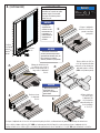
Position Head Track Retainer tight to side jamb in existing screen track. Drill 1/8" holes - 3/4" deep in head jamb, clear
debris, apply sealant in holes, reposition Head Track Retainer, and fasten with #8 x 2" Stainless Steel Screws.
1st
Position Head
Track Retainer.
Slide Head Track
Retainer tighttight
to Side
Jamb. #8 x 2" Stainless Steel Screw
200/400
Series
Drill 1/8" holes,
3/4" deep using
Head Track Retainer
as a guide.
ONLY 3/4"
deep.
· DO NOT drill deeper than
3/4" into head jamb. Doing
so will result in product
damage.
NOTICE
Reposition
Head Track
Retainer.
Apply
Sealant
in holes.
Remove Head
Track Retainer.
3rd
4th 5th
Existing
Screen Track

12
9205707
1/8" holes
No Fastener Required
1st
Snap into kerf
and fully seat
using a rubber
mallet and
wood block.
2nd
Slide Head Track
Retainer tighttight
to Side
Jamb.
A-SeriesA-Series
(continued)
3
· Protect surfaces from tool contact.
Failure to do so could result in
surface marring or product damage.
NOTICE
This area intentionally left blank.
Position Head Track Retainer tight to side jamb and snap into kerf using a rubber mallet and wood block.

13
9205707
Fully open patio door. Measure and mark hole locations 2" from opening ends in head jamb and the midpoint between
marks. Remove and drill 1/8" holes at marked hole locations. Position Head Track Retainer in existing screen track, tight
to side jamb. Mark hole locations using predrilled holes as a guide. Remove and drill 1/8" holes at marked hole locations,
clear debris, and fasten with #8 x 3/8" Self-Drilling Screws.
(continued)
Fasten Head
Track Retainer
with #8 x 3/8"
Self-Drilling Screws.
Reposition
Head Track
Retainer.
Position Head
Track Retainer
in head jamb
Existing Screen
Track.
Mark hole
locations on
Head Track
Retainer.
2nd 3rd 4th
5th
6th
7th
3
Drill 1/8" holes
at marked hole locations
in head jamb groove.
1st
Interior
View
Mark hole
locations on
interior face of
head jamb track
groove.
Interior View
2"2"
Midpoint
Mark 2" from
opening
ends and
the midpoint
between marks.
· Protect surfaces from tool contact.
Failure to do so could result in
surface marring or product damage.
NOTICE
Groove
Remove and
Drill 1/8" holes
at marked hole
locations.
· Only drill through rst wall of component
part, typically about 1/8". Failure to do so
could result in product or property damage.
NOTICE
Slide Head Track
Retainer tighttight
to Side
Jamb.
#8 x 3/8"
Self-Drilling
Screw
E-SeriesE-Series
Existing
Screen Track
Existing
Screen
Track

14
9205707
4
Position Latch Housing Retainer tight to Head Track Retainer and snap into kerf using a rubber mallet and wood block.
#8 x 3/4"
Stainless
Steel Screw
200/400
Series
Position
Latch
Housing
Retainer.
1st
3rd
Drill 1/8" holes,
3/4" deep using
Latch Housing
Retainer as
a guide.
2nd
Snap into kerf,
fully seat using a
rubber mallet and
wood block.
2nd
1st
Position Latch
Housing Retainer.
· Protect surfaces from
tool contact. Failure to
do so could result in
surface marring or
product damage.
NOTICE
· DO NOT drill deeper
than 3/4" into side
jamb. Doing so will
result in product
damage.
NOTICE
No Fastener Required
A-SeriesA-Series
Apply Sealant
in holes and
fasten Latch
Housing
Retainer with
#8 x 3/4"
Stainless Steel
Screws.
Slide Latch Housing Retainer
tight to Head Track
Retainer. DO NOT
overlap Head
Track
Retainer.
Position Latch Housing Retainer to side
jamb, butting up tight to Head Track Retainer.
Drill 1/8" holes - 3/4" deep, clear debris, apply sealant in holes, and fasten with #8 x 3/4" Stainless Steel Screws.

15
9205707
1/8" holes
5
Select Mounting Bracket and fastener color (black or stainless steel).
Slide the Mounting Brackets into the top and bottom of the Screen
Housing, with spring tab towards exterior.
Spring
Tab
4(continued)
· Only drill through
rst wall of component
part, typically about
1/8". Failure to do so
could result in product
or property damage.
NOTICE
· Protect surfaces from tool contact.
Failure to do so could result in
surface marring or product damage.
NOTICE Drill 1/8" holes,
ONLY through the
rst wall using Latch
Housing Retainer as
a guide.
2nd
1st
Position
Latch
Housing
Retainer.
3rd
A-SeriesA-Series
E-SeriesE-Series
200/400
Series
#8 x 3/8"
Self-Drilling
Screw
E-SeriesE-Series
Position Latch Housing Retainer to side jamb, butting up tight to Head Track Retainer. Drill 1/8" holes -
only through the rst wall, clear debris, apply sealant in holes, and fasten with #8 x 3/8" Self-Drilling Screws.
Apply
Sealant in
holes and
fasten
Latch
Housing
Retainer
with
#8 x 3/4"
Self-
Drilling
Screws.
Slide
Mounting
Brackets 2"
past top and
bottom ends
of Screen
Housing.
Screen
Housing

16
9205707
6
A-SeriesA-Series
E-SeriesE-Series
Hook the screen assembly on the Latch Housing Retainer and swing it into position.
200/400
Series
· Make sure Mounting Brackets are positioned past the top and bottom of the screen
assembly before rotating assembly into frame. Failure to do so could cause product damage.
NOTICE
Latch
Housing
Retainer.

17
9205707
7
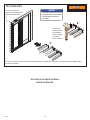
Clamp at the top to hold in place until fastened. Slide the Mounting Bracket down to the Sill Adaptor. Drill a 1/8" hole, clear debris,
and fasten with a #8 x 3/8" Self-Drilling Black or Stainless Steel Screw.
1st 2nd
· Only drill through
rst wall of component
part, typically about
1/8". Failure to do so
could result in product
or property damage.
NOTICE
· Protect surfaces from tool contact.
Failure to do so could result in
surface marring or product damage.
NOTICE
Drill a 1/8"
hole, centered
in exterior slot only.
Fasten with
#8 x 3/8" Self-Drilling
Black or Stainless Steel Screw.
200/400 Series Shown
(Positioning, drilling
and fastening Mounting
Bracket is the same for
all series).
A-SeriesA-Series
E-SeriesE-Series
200/400
Series
#8 x 3/8"
Self-Drilling
Black or Stainless Steel Screw

18
9205707
8
1st 2nd
· Only drill through rst wall of
component part, typically about
1/8". Failure to do so could result
in product or property damage.
NOTICE
Drill a 1/8" hole, centered
in interior slot only.
Verify Retractable Insect Screen is tight to Head Track Retainer and reclamp.
Slide the Mounting Brackets to the Head Track Retainer. Drill a 1/8" hole, clear
debris, and fasten with a #8 x 3/8" Self-Drilling Black or Stainless Steel Screw.
Fasten with #8 x 3/8"
Self-Drilling Black or
Stainless Steel
Screw.
A-SeriesA-Series
E-SeriesE-Series
200/400
Series
#8 x 3/8"
Self-Drilling
Black or Stainless Steel Screw
Installation
is complete.
200/400 Series Shown
(Positioning, drilling
and fastening Mounting
Bracket is the same for
all series).
· Protect surfaces from tool contact.
Failure to do so could result in
surface marring or product damage.
NOTICE

19
9205707
Exterior
Handle
OPEN
Interior
Handle
Slide
Release
Lever
to open.
OPEN
OPEN
OPEN
Retractable
Insect Screen
Housing.
parts.andersenwindows.com
1-800-933-3828 0123456789
Serial Number/No. De Serie
Retractable Insect Screen Label
Label location on
back side of Active
Retractable Screen
Housing (Active
side determined by
your conguration).
Frequently Asked Questions
1. How do I open and close the Retractable Insect Screen?
Use the Handle to extend Retractable Insect Screen. It will
automatically latch when fully extended. Slide the Release
Lever up or down to unlatch. The Retractable Insect Screen
will automatically retract.
2. How do I clean the screen mesh?
Use a clean and soft brush to gently clean the screen mesh
as needed.
3. What should I do to maintain my Retractable Insect
Screen?
The screen tracks will need occasional vacuuming and
rinsing out with water to remove dirt and debris. This will
help keep the tracks clean and free of debris that may
affect operation.
4. Can replacement parts be purchased if something gets
damaged on my Retractable Insect Screen?
Parts can be purchased by visiting
parts.andersenstormdoors.com or calling Customer Service
at 888-888-7020. It is helpful to have your serial number
when ordering parts. The serial number is located on the
back side of your active screen housing.
5. What should I do with the unit in cold weather?
It is best for the unit to be stored in the retracted position
during cold weather. We do not recommend operating when
temperatures are near or below freezing.
6. Will installing the appropriate Retractable Insect Screen
(200/400 Series, A-Series, or E-Series) on an Andersen
gliding patio door void my patio door warranty?
No
7. Is there a video available that will show me how to
install and operate the Retractable Insect Screen?
You can nd a support video to this
installation instruction by
scanning this QR code.

20
9205707
This area intentionally left blank.
La page est en cours de chargement...
La page est en cours de chargement...
La page est en cours de chargement...
La page est en cours de chargement...
La page est en cours de chargement...
La page est en cours de chargement...
La page est en cours de chargement...
La page est en cours de chargement...
La page est en cours de chargement...
La page est en cours de chargement...
La page est en cours de chargement...
La page est en cours de chargement...
La page est en cours de chargement...
La page est en cours de chargement...
La page est en cours de chargement...
La page est en cours de chargement...
La page est en cours de chargement...
La page est en cours de chargement...
La page est en cours de chargement...
La page est en cours de chargement...
La page est en cours de chargement...
La page est en cours de chargement...
La page est en cours de chargement...
La page est en cours de chargement...
La page est en cours de chargement...
La page est en cours de chargement...
La page est en cours de chargement...
La page est en cours de chargement...
La page est en cours de chargement...
La page est en cours de chargement...
La page est en cours de chargement...
La page est en cours de chargement...
La page est en cours de chargement...
La page est en cours de chargement...
La page est en cours de chargement...
La page est en cours de chargement...
La page est en cours de chargement...
La page est en cours de chargement...
La page est en cours de chargement...
La page est en cours de chargement...
La page est en cours de chargement...
La page est en cours de chargement...
La page est en cours de chargement...
La page est en cours de chargement...
La page est en cours de chargement...
La page est en cours de chargement...
-
 1
1
-
 2
2
-
 3
3
-
 4
4
-
 5
5
-
 6
6
-
 7
7
-
 8
8
-
 9
9
-
 10
10
-
 11
11
-
 12
12
-
 13
13
-
 14
14
-
 15
15
-
 16
16
-
 17
17
-
 18
18
-
 19
19
-
 20
20
-
 21
21
-
 22
22
-
 23
23
-
 24
24
-
 25
25
-
 26
26
-
 27
27
-
 28
28
-
 29
29
-
 30
30
-
 31
31
-
 32
32
-
 33
33
-
 34
34
-
 35
35
-
 36
36
-
 37
37
-
 38
38
-
 39
39
-
 40
40
-
 41
41
-
 42
42
-
 43
43
-
 44
44
-
 45
45
-
 46
46
-
 47
47
-
 48
48
-
 49
49
-
 50
50
-
 51
51
-
 52
52
-
 53
53
-
 54
54
-
 55
55
-
 56
56
-
 57
57
-
 58
58
-
 59
59
-
 60
60
-
 61
61
-
 62
62
-
 63
63
-
 64
64
-
 65
65
-
 66
66


