Lumination RUL Series LED Refit Universal Linear Kit Guide d'installation
- Taper
- Guide d'installation

LED.com
© 2023 Current Lighting Solutions, LLC. All rights reserved. Information and specifications subject
to change without notice. All values are design or typical values when measured under laboratory
conditions.
Page 1 of 3
(Rev 06/08/23)
IND408-Lumination-RUL-Series-LED-Refit-Universal-Linear-Kit-Installation-Guide
RISK OF ELECTRIC SHOCK
• Turn power o before inspection, installation or
removal.
• Properly ground electrical enclosure.
• Luminaires wiring and electrical parts may be damaged
when drilling for installation of LED retrot kit. Check for
enclosed wiring and components.
• LED retrot kit installation requires knowledge of
luminairs electrical systems. If not qualied, do not
attempt installation. Contact qualied electrician.
• Install this kit only in luminaires that have the
construction features and dimensions shown in the
photographs and/or drawings and where the input
rating of the retrot kit does not exceed the input rating
of the luminaire.
• To prevent wiring damage or abrasion, do not expose
wiring to edges of sheet metal or other sharp objects.
• This retrot kit is accepted as a component of a
luminaire where the suitability of the combination shall
be determined by authorities having jurisdiction.
RISK OF FIRE
• Follow all NEC and local codes.
• Use only Ul approved wire for input/output connections.
Minimum size 18 AWG or 14 AWG for continuous runs.
RISQUES DE DÉCHARGES ÉLECTRIQUES
• Coupez l’alimentation avant d’inspecter, installer ou déplacer le luminaire.
• Assurez-vous de correctement mettre á la terre le boítier d’alimentation lectrique.
• Le câblage du luminaire ainsi que ses composantes électriques peuvent être
endommagés lors du perçage requis pour l’installation de l’ensemble de mise à
niveau à DEL. Vériez le câblage et les composants.
• L’installation de l’ensemble de mise à niveau à DEL requiert des connaissances en
système électrique d’éclairage. Si vous n’avez pas les qualications adéquates, ne
procédez pas à l’installation et contactez un électricien qualié.
• N’installez cet ensemble de mise à niveau que dans des luminaires ayant
les caractéristiques de construction et les dimensions indiquées dans les
photographies et/ou dessins. La puissance d’entrée de l’ensemble de mise à
niveau ne doit pas excéder la puissance d’entrée nominale du luminaire dans
lequel il est installé.
• An de prévenir tout dommage ou abrasion aux ls électriques, évitez que ceux-
ci ne viennent en contact avec les bordures métalliques ou d’autres ojets pointus.
• Le nécessaire de modernisation est accepté à titre de composant d’un luminaire
lorsque la pertinence de la combinaison doit être déterminée par par les autorités
compétentes.
RISQUES D’ INCENDIE
• Respectez tous les codes NEC et codes locaux.
• N’utilisez que des ls approuvés par UL pour les entrées/sorties de connexion.
Taille minimum 18 AWG ou 14 AWG pour les rangées continues.
Installation Guide
IND408
Ret Universal Linear Kit
(RUL-Series)
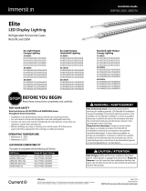
BEFORE YOU BEGIN
Read these instructions completely and carefully.
WARNING/AVERTISSEMENT
This device complies with Part 15 of the FCC Rules. Operation is subject to the following two conditions: (1) This device may not cause
harmful interference, and (2) this device must accept any interference received, including interference that may cause undesired
operation. CAN ICES-005 (A) / NMB-005 (A)
Note: This equipment has been tested and found to comply with the limits for a Class A digital device, pursuant to part 15 of the FCC
Rules. These limits are designed to provide reasonable protection against harmful interference when the equipment is operated in a
commercial environment. This equipment generates, uses, and can radiate radio frequency energy and, if not installed and used in
accordance with the instruction manual, may cause harmful interference to radio communications. Operation of this equipment in
a residential area is likely to cause harmful interference in which case the user will be required to correct the interference at his own
expense.

LED.com
© 2023 Current Lighting Solutions, LLC. All rights reserved. Information and specifications subject
to change without notice. All values are design or typical values when measured under laboratory
conditions.
Page 2 of 3
(Rev 06/08/23)
IND408-Lumination-RUL-Series-LED-Refit-Universal-Linear-Kit-Installation-Guide
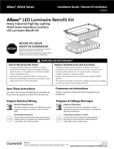
Mounting Clips (4) #6-20 Self Drilling Screws (8)
LED Lightbars (2)
Driver (1)
Relamping Label (1)
Installation Guide (1)
Spec (1)
Prior to installation verify that the
kit contains all components below.
Dim +
Dim –
L
N
LED
Lightbar
LED
Lightbar
1-to-2
LED Driver
0˜10V dim
Lumination® (RUL - Series) Installation Guide
Model Length (mm) Width (mm) Height (mm) Spacing between tubes (mm)
RUL248A0wwxxLB 559 140 x N 50 140
RUL4880wwxxLB 1118 140 x N 50 140
Save These Instructions
Use only in the manner intended by the manufacturer. If you have any questions, contact the manufacturer.
Luminaire Requirements
The unit covered by this report is intended to retrot: Listed surface mounted uorescent luminaires, or Type Non-IC or type IC recessed
mounted uorescent luminaires; with or without diusers that use, straight 2 or 4 ft tubular lamp(s).
Components Supplied
Driver Diagram/Electrical Connections
Prepare Electrical Wiring
Electrical Requirements
• The LED luminaire must be connected to the mains supply
according to its ratings on the product label.
Grounding Instructions
• The grounding and bonding of the overall system shall
be done in accordance with National Electric Code (NEC)
Article 600 and local codes.
N = Number of tubes

LED.com
© 2023 Current Lighting Solutions, LLC. All rights reserved. Information and specifications subject
to change without notice. All values are design or typical values when measured under laboratory
conditions.
Page 3 of 3
(Rev 06/08/23)
IND408-Lumination-RUL-Series-LED-Refit-Universal-Linear-Kit-Installation-Guide
Lumination® (RUL - Series) Installation Guide
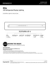
Installation
Attach Mounting Clips
• Snap two mounting clips onto each LED lightbar.
• Bring LED lightbar into housing and reposition the
mounting clips as needed. (For temporary placement of
the lightbar, the mounting clips have magnets located
on the bottom of each clip).
Attach Driver To Housing
• Place new driver into housing and secure. Ensure driver
is properly grounded using a serrated grounding screw
(not supplied).
• Connect the power supply lead connectors to the LED
lightbar connectors.
• Replace ballast cover and ax eld-applied label onto
housing.
2
4
Prepare Existing Fixture For Installation
Prior to installation, disconnect all incoming power to
xture, remove all electrical parts and ballast compartment
cover leaving only the supply and grounding leads.
Remove existing hardware (reectors/ballast covers,
brackets, lamps). Save ballast cover for reuse.
Fasten Lightbars to Housing
Once lightbars are in desired position permanently secure
them to housing by inserting supplied self-tapping screws
into the endcaps on each end of the lightbar.
Close Lens/Door and Secure Latches
1
3
5
Fasten self-tapping screws
Attach mounting clips
AC line
Optional dimming wires
IMPORTANT: Only those open holes indicated in
the photographs and/or drawings may be made or
altered as a result of kit installation. Do not leave
any other open holes in an enclosure of wiring or
electrical components.
-
 1
1
-
 2
2
-
 3
3


Lumination RUL Series LED Refit Universal Linear Kit Guide d'installation
- Taper
- Guide d'installation
dans d''autres langues
Documents connexes
-
Lumination RLB Series Gen 2 LED Strip Retrofit Luminaire Guide d'installation
-
-
-
-
-
-
Autres documents
-
 ARIZE Factor Vertical Farming Troubleshooting guide
-
GE current RefitTM Strip Fixture Retrofit Series Guide d'installation
-
Maxim Lighting 88950WT Manuel utilisateur
-
-
 Immersion LED DIsplay Lighting Elite Series Horizontal Guide d'installation
-
 Albeo AH2 Series Hazardous Locations Heavy Industrial High Bay Retrofit Kit Guide d'installation
-
 Immersion Elite Gen 3 Vertical Case End Mullion Lights Guide d'installation
-
 ARIZE Factor Vertical Farming Guide d'installation
-
Maxim Lighting 88960WT Manuel utilisateur


