Pepperl+Fuchs DK10-LAS/35/49 Mode d'emploi
- Taper
- Mode d'emploi

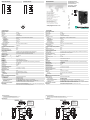
alle Maße in mm
DimensionsAbmessungen
Technische Daten Technical data
Elektrischer Anschluss Electrical connection Adressen/Addresses
Sicherheitshinweise:
•Vor der Inbetriebnahme Betriebsanleitung lesen
• Anschluss, Montage und Einstellung nur durch Fachpersonal
• Kein Sicherheitsbauteil gemäß EU-Maschinenrichtlinie
Security Instructions:
• Read the operating instructions before attempting commissioning
• Installation, connection and adjustments should only be undertaken by specialist personnel
• Not a safety component in accordance with the EU Machinery Directive
all dimensions in mm
www.pepperl-fuchs.com
Pepperl+Fuchs GmbH
68301 Mannheim · Germany
Tel. +49 621 776-4411
Fax +49 621 776-27-4411
E-mail: fa-inf[email protected]
Worldwide Headquarters
Pepperl+Fuchs GmbH · Mannheim · Germany
E-mail: fa-inf[email protected]
USA Headquarters
Pepperl+Fuchs Inc. · Twinsburg · USA
E-mail: fa-inf[email protected]
Asia Pacific Headquarters
Pepperl+Fuchs Pte Ltd · Singapore
E-mail: fa-inf[email protected]
Company Registration No. 199003130E
23
4
5
1
COMPLIES WITH 21 CFR 1040.10
AND 1040.11 EXCEPT FOR DEVIA-
TIONS PURSUANT TO LASER NOTICE
NO. 50, DATED JUNE 24, 2007.
IEC 60825-1: 2007 CERTIFIED.
LASER LIGHT
DO NOT STARE INTO BEAM
CLASS 2 LASER PRODUCT
WAVELENGTH: 650 nm
MAX PULSE ENERGY: 2,1 nJ
PULSE DURATION: 1,5 µs
COMPLIES WITH 21 CFR 1040.10
AND 1040.11 EXCEPT FOR DEVIA-
TIONS PURSUANT TO LASER NOTICE
NO. 50, DATED JUNE 24, 2007.
IEC 60825-1: 2007 CERTIFIED.
LASER LIGHT
DO NOT STARE INTO BEAM
CLASS 2 LASER PRODUCT
WAVELENGTH: 650 nm
MAX PULSE ENERGY: 2,1 nJ
PULSE DURATION: 1,5 µs
Sens.
Scheibe
Hell-/Dunkel-Schalter
Lichtbündelquerschnitt
Empfindlichkeitseinsteller Anzeige-LED
Einschraubtiefe 5
21
M5 (8 x)
23.5
28 1928
38.6
28
19 85.6
1.5 47.9
M12 x 1
16.5
460.8
33
Druckmarken-Kontrasttaster
mit Gerätestecker M12 x 1, 5-polig
Print mark contrast sensor
with 5-pin, M12 x 1 connector
DK10-LAS/35/49
Allgemeine Daten
Tastweite 800 mm
Tastbereich 3 ... 800 mm
Lichtsender Laserdiode
Lichtart rot, Wechsellicht
Laserkenndaten
Hinweis LASERLICHT , NICHT IN DEN STRAHL BLICKEN
Laserklasse 2
Wellenlänge 650 nm
Strahldivergenz < 1,5 mrad
Impulsdauer 1,5 µs
Wiederholrate 108,7 kHz
max. Puls Energie 2,1 nJ
Lichtfleckabbildung ca. 2 mm im Abstand von 800 mm
Fremdlichtgrenze
Gleichlicht 40000 Lux
Kenndaten funktionale Sicherheit
MTTFd 550 a
Gebrauchsdauer (TM) 20 a
Diagnosedeckungsgrad (DC) 60 %
Anzeigen/Bedienelemente
Funktionsanzeige LED gelb: leuchtet, wenn Empfänger belichtet (Hellschaltung)
leuchtet, wenn Empfänger unbelichtet (Dunkelschaltung)
Bedienelemente Hell-/Dunkel-Umschalter, Empfindlichkeitseinsteller
Elektrische Daten
Betriebsspannung UB10 ... 30 V DC
Welligkeit 10 %
Leerlaufstrom I0≤ 55 mA
Eingang
Testeingang Senderabschaltung mit +Ub
Ausgang
Schaltungsart hell-/dunkelschaltend umschaltbar
Signalausgang 1 PNP und 1 NPN, kurzschlussfest, offene Kollektoren, gleichschaltend
Schaltspannung max. 30 V DC
Schaltstrom max. 200 mA
Schaltfrequenz f 16,5 kHz
Ansprechzeit 30 µs
Umgebungsbedingungen
Umgebungstemperatur -10 ... 50 °C (14 ... 122 °F)
Lagertemperatur -20 ... 75 °C (-4 ... 167 °F)
Mechanische Daten
Schutzart IP67
Anschluss Gerätestecker M12 x 1, 5-polig
Material
Gehäuse PC (Makrolon, glasfaserverstärkt)
Lichtaustritt Glas
Masse 200 g
Normen- und Richtlinienkonformität
Richtlinienkonformität EMV-Richtlinie 2004/108/EG
Normenkonformität
Produktnorm EN 60947-5-2:2007
IEC 60947-5-2:2007
Schock- und Stoßfestigkeit IEC / EN 60068, Halb-Sinus, 40 g je X, Y und Z Richtung
Vibrationsfestigkeit IEC / EN 60068-2-6, Sinus, 10 - 150 Hz, 5 g je X, Y und Z Richtung
Laserklasse IEC 60825-1:2007 Complies with 21 CFR 1040.10 and 1040.11 except for deviations
pursuant to Laser Notice No. 50, dated June 24, 2007
Zulassungen und Zertifikate
UL-Zulassung cULus Listed , Class 2 Power Source
CCC-Zulassung Produkte, deren max. Betriebsspannung ≤36 V ist, sind nicht zulassungspflichtig und
daher nicht mit einer CCC-Kennzeichnung versehen.
23
4
5
1
COMPLIES WITH 21 CFR 1040.10
AND 1040.11 EXCEPT FOR DEVIA-
TIONS PURSUANT TO LASER NOTICE
NO. 50, DATED JUNE 24, 2007.
IEC 60825-1: 2007 CERTIFIED.
LASER LIGHT
DO NOT STARE INTO BEAM
CLASS 2 LASER PRODUCT
WAVELENGTH: 650 nm
MAX PULSE ENERGY: 2,1 nJ
PULSE DURATION: 1,5 µs
COMPLIES WITH 21 CFR 1040.10
AND 1040.11 EXCEPT FOR DEVIA-
TIONS PURSUANT TO LASER NOTICE
NO. 50, DATED JUNE 24, 2007.
IEC 60825-1: 2007 CERTIFIED.
LASER LIGHT
DO NOT STARE INTO BEAM
CLASS 2 LASER PRODUCT
WAVELENGTH: 650 nm
MAX PULSE ENERGY: 2,1 nJ
PULSE DURATION: 1,5 µs
Sens.
Shield
Bright/dark switch
Light beam cross-section
Sensitivity adjuster Display LED
Screw in depth 5
21
M5 (8 x)
23.5
28 1928
38.6
28
19 85.6
1.5 47.9
M12 x 1
16.5
460.8
33
11/27/2014
Date:
3
2
1
4
5
+UB
0 V
Q1
Q2
Test
/49
1
3
4
5
2
General specifications
Sensor range 800 mm
Detection range 3 ... 800 mm
Light source laser diode
Light type modulated visible red light
Laser nominal ratings
Note LASER LIGHT , DO NOT STARE INTO BEAM
Laser class 2
Wave length 650 nm
Beam divergence < 1.5 mrad
Pulse length 1.5 µs
Repetition rate 108.7 kHz
max. pulse energy 2.1 nJ
Light spot representation approx. 2 mm at a distance of 800 mm
Ambient light limit
Continuous light 40000 Lux
Functional safety related parameters
MTTFd 550 a
Mission Time (TM) 20 a
Diagnostic Coverage (DC) 60 %
Indicators/operating means
Function indicator LED yellow: lights up if receiver is lit (light on), lights up if receiver is not lit (dark on)
Control elements Light/Dark switch, sensitivity adjuster
Electrical specifications
Operating voltage UB10 ... 30 V DC
Ripple 10 %
No-load supply current I0≤ 55 mA
Input
Test input emitter deactivation with +Ub
Output
Switching type light/dark on switchable
Signal output 1 PNP and 1 NPN short-circuit protected, open collector, synchronized-switching
Switching voltage max. 30 V DC
Switching current max. 200 mA
Switching frequency f 16.5 kHz
Response time 30 µs
Ambient conditions
Ambient temperature -10 ... 50 °C (14 ... 122 °F)
Storage temperature -20 ... 75 °C (-4 ... 167 °F)
Mechanical specifications
Degree of protection IP67
Connection 5-pin, M12 x 1 connector
Material
Housing PC (glass-fiber-reinforced Makrolon)
Optical face glass
Mass 200 g
Compliance with standards and direc-
tives
Directive conformity EMC Directive 2004/108/EC
Standard conformity
Product standard EN 60947-5-2:2007
IEC 60947-5-2:2007
Shock and impact resistance IEC / EN 60068. half-sine, 40 g in each X, Y and Z directions
Vibration resistance IEC / EN 60068-2-6. Sinus. 10 -150 Hz, 5 g in each X, Y and Z directions
Laser class IEC 60825-1:2007 Complies with 21 CFR 1040.10 and 1040.11 except for deviations
pursuant to Laser Notice No. 50, dated June 24, 2007
Approvals and certificates
UL approval cULus Listed , Class 2 power source
CCC approval CCC approval / marking not required for products rated ≤36 V
3
2
1
4
5
+UB
0 V
Q1
Q2
Test
/49
DIN A3 -> A7
Part. 418071 45-0377G
Doc.

• Die Bestrahlung kann zu Irritationen gerade bei dunkler Umgebung führen. Nicht auf Menschen richten!
• Vorsicht: Laserlicht, nicht in den Strahl blicken!
• Wartung und Reparaturen nur von autorisiertem Servicepersonal durchführen lassen!
• Das Gerät ist so anzubringen, dass die Warnhinweise deutlich sichtbar und lesbar sind.
• Vorsicht: Wenn andere als die hier angegebenen Bedienungs- oder Justiereinrichtungen benutzt oder
andere Verfahrensweisen ausgeführt werden, kann dies zu gefährlicher Strahlungseinwirkung führen.
• The irradiation can lead to irritation especially in a dark environment. Do not point at people!
• Caution: Do not look into the beam!
• Maintenance and repairs should only be carried out by authorized service personnel!
• Attach the device so that the warning is clearly visible and readable.
• Caution – Use of controls or adjustments or performance of procedures other than those specified her-
ein may result in hazardous radiation exposure.
• L’irradiation peut entraîner des irritations dans un environnement sombre.
Ne pas orienter vers les personnes !
• Attention : ne pas observer la lumière laser dans le faisceau !
• L’entretien et les réparations doivent être réalisés exclusivement par le personnel de service autorisé !
• L’appareil doit être installé de manière à ce que les mises en garde soient clairement visibles et lisibles.
• Attention : Si d’autres dispositifs de commande ou de réglage sont utilisés que ceux indiqués ici, ou si
d’autres procédures sont exécutées, cela peut entraîner un effet préjudiciable du rayonnement.
LASERLICHT
LASER LIGHT
NICHT IN DEN STRAHL BLICKEN
DO NOT STARE INTO BEAM
LASER KLASSE 2
CLASS 2 LASER PRODUCT
Einstellung der Schaltschwelle
Die gewünschte Schaltschwelle wird mit dem Empfindlichkeitsregler eingestellt. Dazu ist wie
folgt vorzugehen:
1. Hell-/Dunkelumschalter in Stellung Hellschaltung bringen.
2. Lichtfleck auf den hellen Teil der abzutastenden Fläche richten.
3. Leuchtet gelbe Anzeige-LED, Empfindlichkeitsregler nach links drehen bis
Anzeige erlischt.
Leuchtet gelbe LED nicht, diesen Schritt überspringen.
4. Empfindlichkeitsregler nach rechts drehen bis Anzeige-LED gerade auf-
leuchtet.
5. Lichtfleck auf den dunklen Teil der abzutastenden Fläche richten.
6. Anzeige-LED muss erloschen sein.
7. Empfindlichkeitsregler weiter nach rechts drehen, bis Anzeige-LED wie-
der aufleuchtet, dabei Anzahl der Umdrehungen zählen.
8. Empfindlichkeitsregler um die Hälfte der gezählten Umdrehungen nach
links drehen.
Wird der DK10 so eingestellt, liegt die Schaltschwelle genau in der Mitte der gemessenen
Hell- und Dunkelwerte. Je größer die Anzahl der Umdrehungen des Empfindlichkeitsreglers
zwischen Hell- und Dunkelmarke, desto größer ist der Kontrast.
Empfehlung: Die Anzahl der Umdrehungen sollte > 0,5 betragen.
Einstellung der Schaltungsart:
Switching threshold adjustment
The required switching threshold is adjusted with the sensitivity control. Please proceed as
follows:
1. Switch the light/dark change-over switch to the light setting.
2. Point the light spot at the light part of the surface being scanned.
3. If the yellow indicator LED lights up, turn the sensitivity control to the left
until the indicator LED goes off again.
If the yellow indicator LED does not light up, miss out this step.
4. Turn the sensitivity control to the right until the indicator LED just lights up.
5. Point the light spot at the dark part of the surface being scanned.
6. The indicator LED must have gone off.
7. Turn the sensitivity control to the right again until the indicator LED lights
up again. Counting the number of turns.
8. Turn the sensitivity control back to the left by half the number of counted
turns.
Once the DK10 colour mark scanner has been adjusted in this way, the switching thres-hold
is exactly in the middle of the measured light and dark values. The greater the number the
number of times the sensitivity control is turned between the light and the dark marks, the
greater the contrast.
Recommendation: The number of turns should be to > 0.5.
Switching mode adjustment:
Le seuil de commutation souhaité est réglé par l’intermédiaire du régulateur de sensibilité. Il
faut procéder de la sorte:
1. Mettre le commutateur “éclairement/obscurcissement” en position com-
mutation éclairement.
2. Diriger le spot lumineux sur la partie claire de la surface à balayer.
3. Si la LED d’affichage jaune est allumée, tourner le régulateur de sensibi-
lité vers la gauche jusqu’à ce que l’affichage s’éteigne. Si la LED jaune ne
s’allume pas, passer à l’étape suivante.
4. Tourner le régulateur de sensibilitè vers la droite jusqu’à ce que le LED
d’affichage s’allume.
5. Diriger le spot lumineux sur la partie foncée de la surface à balayer.
6. La LED d’affichage doit être éteinte.
7. Continuer à tourner le régulateur de sensibilité vers la droite jusqu’à ce
que la LED d’affichage de nouveau, compter alors le nombre de tours.
8. Tourner le régulateur de sensibilitè vers la gauche de la moitié du nombre
de tours comptés.
Si le DK10 est réglé de la sorte, le seuil de commutation se situe exactement à la moitié des
valeurs “éclairement” et “obscurcissement” mesurées. Plus le nombre de tours du régulateur
de sensibilité entre la position de commutation “éclairement” et celle de commutation “obs-
curcissement” est élevé, plus le contraste est important.
Recommandation : Le nombre de tours devrait être > 0,5.
Einstellung der Schaltschwelle
Die gewünschte Schaltschwelle wird mit dem Empfindlichkeitsregler eingestellt. Dazu ist wie
folgt vorzugehen:
1. Hell-/Dunkelumschalter in Stellung Hellschaltung bringen.
2. Lichtfleck auf den hellen Teil der abzutastenden Fläche richten.
3. Leuchtet gelbe Anzeige-LED, Empfindlichkeitsregler nach links drehen bis
Anzeige erlischt.
Leuchtet gelbe LED nicht, diesen Schritt überspringen.
4. Empfindlichkeitsregler nach rechts drehen bis Anzeige-LED gerade auf-
leuchtet.
5. Lichtfleck auf den dunklen Teil der abzutastenden Fläche richten.
6. Anzeige-LED muss erloschen sein.
7. Empfindlichkeitsregler weiter nach rechts drehen, bis Anzeige-LED wie-
der aufleuchtet, dabei Anzahl der Umdrehungen zählen.
8. Empfindlichkeitsregler um die Hälfte der gezählten Umdrehungen nach
links drehen.
Wird der DK10 so eingestellt, liegt die Schaltschwelle genau in der Mitte der gemessenen
Hell- und Dunkelwerte. Je größer die Anzahl der Umdrehungen des Empfindlichkeitsreglers
zwischen Hell- und Dunkelmarke, desto größer ist der Kontrast.
Empfehlung: Die Anzahl der Umdrehungen sollte > 0,5 betragen.
Einstellung der Schaltungsart:
Switching threshold adjustment
The required switching threshold is adjusted with the sensitivity control. Please proceed as
follows:
1. Switch the light/dark change-over switch to the light setting.
2. Point the light spot at the light part of the surface being scanned.
3. If the yellow indicator LED lights up, turn the sensitivity control to the left
Laserhinweis Laserklasse 2
Laser notice laser class 2
Consigne laser classe 2
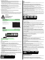
Stellung
H/D-Schalter
Empfänger Ausgang
PNP
Ausgang
NPN
Hbelichtet nicht aktiv aktiv
unbelichtet aktiv nicht aktiv
Dbelichtet aktiv nicht aktiv
unbelichtet nicht aktiv aktiv
-0.8
-0.6
-1.2
-1.4
-1.0
-0.4
-0.2
0.0
0
0.2
0.4
0.6
0.8
1.2
1.4
1.0
100 200 300 400 500 600 700 800
[x / mm]
[y / mm]
x
DK10-LAS/35*
Strahldivergenz
Divergence du faisceau
Divergenza radiativa
Beam divergence
Divergencia del haz
Lichtfleckgröße Y / mm
Size of the light spot Y / mm
Encombrement de la tache lumineuse Y / mm
Tamaño del haz de luz Y / mm
Grandezza chiazza luce Y / mm
0 100 200 300 400 500 600 700 800
Tastbereiche
Detection ranges
Distanzas utiles
Rangos de detección
Domaines de detection
Objektfarbe/Object colour
Couleur de l'objet/Color objeto
Colore oggetto
18 %
90 %
x
X [mm]
DK10-LAS/35
Einstellhinweise/adjustment instructions/
Instructions du réglage
Setting of
light/dark
switch
Receiver Output
PNP
Output
NPN
Hexposed inactive active
unexposed active inactive
Dexposed active inactive
unexposed inactive active
Stellung
H/D-Schalter
Empfänger Ausgang
PNP
Ausgang
NPN
Hbelichtet nicht aktiv aktiv
unbelichtet aktiv nicht aktiv
Dbelichtet aktiv nicht aktiv
unbelichtet nicht aktiv aktiv
Einstellhinweise
Adjustment instructions
-
 1
1
-
 2
2


Pepperl+Fuchs DK10-LAS/35/49 Mode d'emploi
- Taper
- Mode d'emploi
dans d''autres langues
Documents connexes
-
Pepperl+Fuchs DK10-LAS/9S50/76a/110/124 Mode d'emploi
-
-
-
-
-
-
-
-
-