Miele PWM 520 Installation Diagram
- Catégorie
- Machines à laver
- Taper
- Installation Diagram

PWM 520 EH
en Installation Plan Commercial Washing Machine
fr Schéma d’installation Lave-linge professionnel
M.-Nr. 12 173 760


en - Contents
3
Installation notes ............................................................................................................. 4
Explanation of the safety notes and warnings on the machine......................................... 4
Installation requirements ................................................................................................... 4
General operating conditions ............................................................................................ 4
Installation ......................................................................................................................... 4
Installation on concrete base ............................................................................................ 5
Leveling the machine......................................................................................................... 5
Securing the machine........................................................................................................ 6
Electrical connection......................................................................................................... 6
Water connection .............................................................................................................. 7
Cold-water connection.................................................................................................. 7
Warm/Hot water connection ......................................................................................... 8
Drain valve..................................................................................................................... 8
Dispenser pump connections ........................................................................................... 9
Optional accessories......................................................................................................... 10
Hard-water kit (APWM062) ........................................................................................... 10
APWM019/020 Connector Box.................................................................................... 10
Base (APWM022/035).................................................................................................. 12
WiFi/LAN interface ........................................................................................................ 12
Vapor and suds venting kit (APWM063)....................................................................... 12
Installation........................................................................................................................ 13
Standard............................................................................................................................ 13
Stand................................................................................................................................. 15
Installation........................................................................................................................ 17
Standard............................................................................................................................ 17
Stand................................................................................................................................. 18
Floor anchoring ................................................................................................................. 19
Technical details.............................................................................................................. 20
Electrical version and electrical data................................................................................. 20
Water connection .............................................................................................................. 20
Cold water connection.................................................................................................. 20
Hot water connection (for variants without heating) ..................................................... 20
Hard water connection (optional).................................................................................. 20
Drainage ............................................................................................................................ 20
Connection for equipotential bonding............................................................................... 20
Installation dimensions...................................................................................................... 21
Anchoring .......................................................................................................................... 21
Transport data, weight and floor load ............................................................................... 21
Models with detergent drawer (DD) .............................................................................. 21
Emissions data .................................................................................................................. 21

en - Installation notes
*INSTALLATION*
4
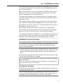
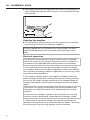
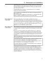
Explanation of the safety notes and warnings on the ma-
chine
Read the operating instructions
Read all the instructions, e.g., the installation instruc-
tions
Warning, hot surfaces
Warning, voltage up to 1000volts
Grounding
Equipotential bonding
Installation requirements
The washing machine must be installed by Miele Service or by
properly trained staff of an authorized dealer.
This washing machine must be installed in accordance with all rel-
evant regulations and standards. Local energy supplier regulations
must also be observed.
This washing machine must only be operated in a room that has
sufficient ventilation and which is frost-free.
The washing machine should not be installed or operated in any
area where there is a risk of explosion.
General operating conditions
This washing machine is intended only for use in a commercial envi-
ronment and must only be operated indoors.
- Ambient temperature: 32-105°F (0-40°C)
- Relative humidity: non-condensing
- Maximum height above sea level of location site: 6500 ft (2000 m)
Depending on the nature of the installation site, sound emissions and
vibration may occur.
Tip: Have the installation site inspected and seek the advice of a spe-
cialist in instances where increased noise may cause a nuisance.
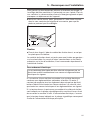
Installation
This washing machine must be transported to its installation site us-
ing a suitable pallet truck. Remove the transport packaging.

en - Installation notes
*INSTALLATION*
5
The washing machine must be set up on a completely level, horizon-
tal, and firm surface with the minimum stated load bearing capacity
(see “Technical data”).
Tip: A concrete floor is the most suitable installation surface for this
machine. It is far less prone to vibration during the spin cycle than
wooden floorboards or a carpeted surface.
The floor load created by the washing machine is the load exerted
by the area of the machine in contact with and transferred to the in-
stallation surface.
The washing machine requires a gap of at least 2" (50mm) on each
side to allow for movement during operation. Please ensure a mini-
mum distance of 15 3/4" (400mm) is maintained between the rear of
the appliance and the rear wall.
The washing machine must not be installed on a carpeted floor.
The feet of the washing machine must be secured to the fastening
points on the floor using the fixtures and fastenings supplied.
The material provided is intended for use in bolting the machine to a
concrete floor. If other floor types are present at the installation site,
the fixtures and fastenings must be provided by the customer.
Installation on concrete base
The washing machine can be installed on a concrete base if desired.
The concrete materials and the durability of the concrete base must
be assessed in accordance with the floor load bearing capacity
given in “Technical data”.
To guarantee the stability of the washing machine, make sure that
the concrete base is sufficiently stable on the floor and that it is ca-
pable of withstanding any burden or force from the washing ma-
chine.
The washing machine must be secured to the concrete base using
the fixtures and fastenings supplied.
The washing machine must be secured to the base immediately
after installation!
There is a risk of the washing machine falling off a raised base dur-
ing a spin cycle if it is not secured.
Leveling the machine
Align the washing machine vertically and horizontally using the ad-
justable feet and a level.
The washing machine must stand perfectly level on all four feet to
ensure safe and proper operation. Otherwise water and energy con-
sumption will be increased and the machine could move.

en - Installation notes
*INSTALLATION*
6
After aligning the machine tighten the lock nuts by turning them in a
counterclockwise direction with a wrench. This will prevent the feet
from moving.
Securing the machine
The feet of the washing machine must be secured to the concrete
base using the fixtures and fastenings supplied.
Fittings supplied are for installation on a concrete floor. For other
types of flooring please purchase suitable fitting materials sepa-
rately.
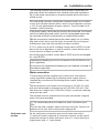
Electrical connection
The electrical connection must only be carried out by a qualified
electrician who must ensure that all electrical work is carried out in
accordance with applicable electrical regulations and standards.
The washing machine must be connected to an electrical supply
that complies with local and national regulations. Please also observe
your insurance and energy supplier's regulations as well as any health
and safety at work regulations.
The required voltage, power consumption and specifications for
external fusing are quoted on the data plate on the washing machine.
Ensure that the supply voltage complies with the voltage quoted on
the data plate before connecting the washing machine to the power
supply.
Connection to a supply voltage other than the one quoted on the
data plate can lead to functional faults and damage the washing
machine.
If more than one voltage is quoted on the data plate, the washing
machine can be converted for connection to the voltages stated.
Conversion to a different voltage must only be carried out by a
Miele Service engineer or by an authorized Service Dealer. The wiring
instructions given on the wiring diagram must be followed.

en - Installation notes
*INSTALLATION*
7
The washing machine can either be hard-wired or connected via a
plug and socket that complies with national codes and regulations.
For a hard-wired connection an all-pole isolation device must be in-
stalled on site.
For hard-wired machines connection should be made via a suitable
switch with all-pole isolation which, when in the off position, ensures
a 1/8" (3 mm) gap between all open contacts. These include circuit
breakers, fuses and relays.
If the power supply cannot be permanently disconnected, the isolator
switch (including plug and socket) must be safeguarded against be-
ing switched on either unintentionally or without authorization.
Tip: We recommend connection to the power supply via a suitable
plug and socket which must be easily accessible for servicing and
maintenance work after the machine has been installed.
If it is necessary to install a residual current device (RCD) in accor-
dance with local regulations, a typeB residual current device (sensi-
tive to universal current) must be used.
An existing typeA residual current device (RCD) must be exchanged
for a typeB RCD.
Equipotential bonding must be in accordance with all national and
local regulations.
Accessories for equipotential bonding are not supplied and need to
be ordered separately.
Water connection
The washing machine complies with current local and national
safety regulations protecting the drinking water supply and can
therefore be connected to the drinking water supply without a non-
return valve.
The flow pressure must amount to a minimum of 100kPa (14.5psi)
and must not exceed an overpressure of 1,000kPa (145psi). If the
flow pressure is higher than 1,000kPa (145psi), a pressure reducing
valve must be used.
The machine must be connected to the water connection using the
water inlet hoses provided.
The connection points are subject to water connection pres-
sure.
Turn on the water supplies slowly and check for leaks. Correct the
position of the seal and screw thread if appropriate.
Cold-water con-
nection
For the cold-water connection one shut-off valve each with a
¾" external thread is required. A connector (Y-piece) can be used if
required to connect 2water inlet hoses with a ¾" screw thread to a
single faucet with a 1" male thread.

en - Installation notes
*INSTALLATION*
8
The water inlet hose for cold water (blue stripes) is not intended to
be used with a hot-water connection.
Warm/Hot water
connection To minimize energy consumption during operation with hot water,
the washing machine should be connected to a suitable hot water
ring circuit if present.
So-called “transmission lines” (single lines to hot water generators)
can result in cooling down of the water remaining in the pipes if not
in constant use. More electrical energy would be needed in order to
heat the suds.
Use the water inlet hose supplied (red stripes) for the hot water con-
nection.
The temperature of the warm water intake must not exceed 158 °F
(70 °C) on machines with electric heating(EL).
The temperature of the hot water intake must not exceed
194°F(90°C) on machines without heating(EH).
The machine must be connected to the water supply using the inlet
hoses provided.
If there is no hot water supply at the installation location, the hot wa-
ter inlet hose must also be connected to the cold water supply. An
additional Y-piece is required in this case. Cold water consumption of
the washing machine increases accordingly to account for the miss-
ing hot water inlet.
For functional and technical reasons it is not possible to operate
the machine exclusively with a hot water connection.
Even if a hot water connection is present, the washing machine
must be connected to a cold water inlet.
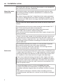
Drain valve In the case of washing machines with a drain valve, a motorized valve
is used to drain the machine. A 2¾" angle connector can be used for
connecting the drain valve directly into the waste water system (with-
out a siphon) or into a floor drain (on-site gully with odor trap).
Thanks to an improved closing mechanism and a larger cross-sec-
tion, even the coarsest of soil does not leave any deposits or debris
behind which could result in blockages. The drain valve can also be
operated manually to allow the suds container to be emptied in the
event of a power failure.
A vented drainage system is vital for unimpeded drainage.
If several machines are connected to a single drain pipe, this
should be sufficiently large to allow all machines to drain simultane-
ously.
If the slope for drainage is extremely steep, the piping must be
vented to prevent formation of a vacuum in the machine’s drainage
system.

en - Installation notes
*INSTALLATION*
9
Slow or obstructed drainage or a backup of water in the drum as a re-
sult of undersized pipework can result in faults occurring during pro-
gram sequences, which will result in fault messages appearing in the
machine display.
Outflowing suds can be as hot as 203°F (95°C). Danger of injury
by burning!
Avoid direct contact.
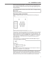
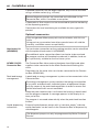
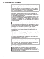
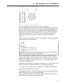
Dispenser pump connections
Up to 12dispenser pumps can be connected to the washing ma-
chine.
Dispenser pump connections on the back of the machine
Connections 1 and 2 are provided for viscous agents and can also be
used for high-pressure dispensing systems with water injection. The
dispensing systems must be equipped with a separate drinking water
safety feature in accordance with EN61770 and EN1717. The maxi-
mum flow rate is 1,500ml/min with a maximum flow pressure of
43psi(300 kPa).
These connectors are sealed and need to be drilled open using an
8mm drill bit before connecting.
Care must be taken to drill through the first wall only(I) as there is a
deflecting wall(II) 3/8" (10mm) behind it.
Connections3 to 12 are provided for liquid detergent. High-pressure
dispensing systems with water injection must not be connected to
these connections. The connectors are sealed and must be cut to the
diameter of the hose with a small saw before they are connected.

en - Installation notes
*INSTALLATION*
10
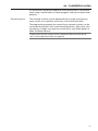
If opened connectors are no longer required, they must be resealed
using a suitable sealant (e.g., silicone).
External dispenser pumps are connected and calibrated via the
Connector Box, which is available as an option.
A flowmeter or flow sensors can be connected for precise monitoring
of the dispensing quantity.
Connections for level monitoring are available for every agent dis-
pensed.
Optional accessories
Only use genuine Miele spare parts and accessories with this ma-
chine.
Using parts or accessories from other manufacturers will void the
warranty, and Miele cannot accept liability.
Hard-water kit
(APWM062)
The hard-water connection on the washing machine can be retrofitted
with the optional hard-water kit (APWM062).
The additional water connection allows hard water to be used and
the program runtime will therefore be reduced. In addition, hard wa-
ter is particularly suitable for the final rinse cycles.
APWM019/020
Connector Box
The Connector Box allows external hardware from Miele and other
suppliers to be connected to the Miele Professional Washing Ma-
chine.
Flowmeters for the water inlet can also be connected to the Connec-
tor Box (APWM065).
Peak load/energy
management
A peak-load or energy management system can be connected via the
Connector Box.
The energy management system monitors the energy consumption
of a system and deactivates individual pieces of equipment tempo-
rarily by means of the peak-load negotiation in order to ensure that
certain total load limits are not exceeded.
When the peak-load function is activated, the heating is deactivated
and the program stopped. A message appears in the display to in-
form you of this.
The program is resumed automatically when the peak-load function
finishes.
Liquid dispensing
connection
External liquid dispenser pumps with a “container empty” indicator
and/or flowmeter can be used via the Connector Box to dispense liq-
uid detergents.
The dispenser pumps can only be programmed by Miele Customer
Service.

en - Installation notes
*INSTALLATION*
11
It is particularly important to observe the manufacturer’s instructions
when using a combination of cleaning agents and special application
products.
Payment device The washing machine can be equipped with a single-machine pay-
ment system as an optional accessory via the Connector Box.
The programming required for connecting a payment system can be
carried out during the initial commissioning process. After initial com-
missioning, changes may only be carried out by your Miele dealer or
Miele Customer Service.
Please note that the status of the Connector Box must be set to
“on” in the supervisor level as required.

en - Installation notes
*INSTALLATION*
12
Base
(APWM022/035)
The washing machine can be installed on a machine base (open or
box base, available as an optional Miele accessory).
Elevating the washing machine gives a better ergonomic working
position when loading or unloading. At the same time it facilitates
the installation of a drain connection.
The washing machine must be secured to the base immediately
after installation! The base must be secured to the floor!
There is a risk of the washing machine falling off a raised base dur-
ing a spin cycle if it is not secured.
WiFi/LAN inter-
face
The washing machine is equipped with a WiFi/LAN interface for ex-
changing data.
The data interface provided on the LAN connection complies with
SELV (Safety Extra Low Voltage) in accordance with EN60950. The
LAN connection uses a RJ45 connector in accordance with EIA/
TIA568-B.
Connected machines must also comply with SELV.
Vapor and suds
venting kit
(APWM063)
If excessive suds form, suds may escape from the vapor vent. An op-
tional vapor and foam venting kit can be used to remove the foam.

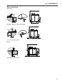
en - Installation
13
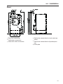
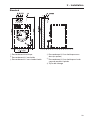
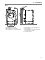
Standard
aElectrical connection
bCold water connection
cWarm/hot water connection
dCold water connection for hard water (op-
tional)
eCold water connection for liquid dispens-
ing
lDrain pipe

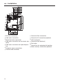
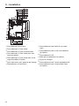
en - Installation
14
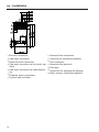
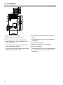
aElectrical connection
bCold water connection
cWarm/hot water connection
dCold water connection for hard water (op-
tional)
eCold water connection for liquid dispens-
ing
fDispenser pump connections
gOverflow and ventilation
hConnector Box connection
iConnector Kit connection (optional)
jLAN connection
kConnector Box (optional)
lDrain pipe
mConnection for equipotential bonding
sWater recovery connection (optional)

en - Installation
15
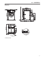
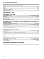
Stand
aElectrical connection
bCold water connection
cWarm/hot water connection
dCold water connection for hard water (op-
tional)
eCold water connection for liquid dispens-
ing
lDrain pipe

en - Installation
16
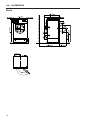
aElectrical connection
bCold water connection
cWarm/hot water connection
dCold water connection for hard water (op-
tional)
eCold water connection for liquid dispens-
ing
fDispenser pump connections
gOverflow and ventilation
hConnector Box connection
iConnector Kit connection (optional)
jLAN connection
kConnector Box (optional)
lDrain pipe
mConnection for equipotential bonding
sWater recovery connection (optional)

en - Installation
*INSTALLATION*
17
Standard
Machine feet

en - Installation
*INSTALLATION*
18
Stand

en - Installation
*INSTALLATION*
19
Floor anchoring
Standard
Multiple side-by-side installation
screw/anchor point
Stand
screw/anchor point

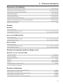
en - Technical details
20
Electrical version and electrical data
Connection voltage 240 V1 Ph 3 Wire
Frequency 60 Hz
Total amps. 17 A
Max. fuse (time delay fuse) 20 A
Mimimum circuit ampacity 17 A
Water connection
Cold water connection
Required flow pressure 1.45-145 psi (100-1000 kPa/1-10 bar)
Maximum flow rate 31.5 l/min
Threaded union required (male thread, to be provided by customer in accordance with
DIN44991, flat sealing)
3 x 3/4"
Length of water inlet hose supplied 3x61" (1.55 m)
Hot water connection (for variants without heating)
Maximum permissible hot water temperature 194 °F (90 °C)
Required flow pressure 1.45-145 psi (100-1000 kPa/1-10 bar)
Maximum flow rate 16 l/min
Threaded union required (male thread, in accordance with DIN44991, flat sealing) 1 x 1"
Length of water inlet hose supplied 61" (1.55 m)
Hard water connection (optional)
Required flow pressure 1.45-145 psi (100-1000 kPa/1-10 bar)
Maximum flow rate 32 l/min
Threaded union required (male thread, in accordance with DIN44991, flat sealing) 2 x 3/4"
Length of water inlet hose supplied 2x61" (1.55 m)
Drainage
Maximum drain water temperature 203°F (95°C)
Waste water connection (on machine) Plastic pipe HTDN 70
Drain (on site) ConnectionDN 70
Maximum drainage rate 200 l/min
Connection for equipotential bonding
Male thread M10
Toothed washers M10
La page est en cours de chargement...
La page est en cours de chargement...
La page est en cours de chargement...
La page est en cours de chargement...
La page est en cours de chargement...
La page est en cours de chargement...
La page est en cours de chargement...
La page est en cours de chargement...
La page est en cours de chargement...
La page est en cours de chargement...
La page est en cours de chargement...
La page est en cours de chargement...
La page est en cours de chargement...
La page est en cours de chargement...
La page est en cours de chargement...
La page est en cours de chargement...
La page est en cours de chargement...
La page est en cours de chargement...
La page est en cours de chargement...
La page est en cours de chargement...
La page est en cours de chargement...
La page est en cours de chargement...
-
 1
1
-
 2
2
-
 3
3
-
 4
4
-
 5
5
-
 6
6
-
 7
7
-
 8
8
-
 9
9
-
 10
10
-
 11
11
-
 12
12
-
 13
13
-
 14
14
-
 15
15
-
 16
16
-
 17
17
-
 18
18
-
 19
19
-
 20
20
-
 21
21
-
 22
22
-
 23
23
-
 24
24
-
 25
25
-
 26
26
-
 27
27
-
 28
28
-
 29
29
-
 30
30
-
 31
31
-
 32
32
-
 33
33
-
 34
34
-
 35
35
-
 36
36
-
 37
37
-
 38
38
-
 39
39
-
 40
40
-
 41
41
-
 42
42


Miele PWM 520 Installation Diagram
- Catégorie
- Machines à laver
- Taper
- Installation Diagram
dans d''autres langues
- English: Miele PWM 520
Documents connexes
-
Miele PWM 514 Installation Diagram
-
-
-
Miele PW 6241 Installation Diagram
-
-
-
-
Miele PG 8056 Installation Plan
-
Miele 51613745USA Mode d'emploi
-
Miele PFD 104 SCVi XXL Installation Plan