
1-Page_entete
WARNING
ATTENTION
A11 OFF
NON
*
HOOD
PIN
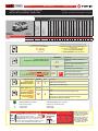
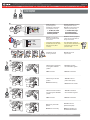
HOOD STATUS : THE HOOD PIN SWITCH (INCLUDED)
MUST BE INSTALLED IF THE VEHICLE CAN BE
REMOTE STARTED WITH THE HOOD OPEN, SET FUNCTION A11 TO OFF.
CONTACT
DE CAPOT
SECURITY STICKER
AUTOCOLLANT DE
SÉCURITÉ
MANDATORY INSTALL | INSTALLATION OBLIGATOIRE Notice: the installation of safety
elements are mandatory. The hood pin
and the sticker are essential security
elements and must be installed.
Notice: l'installation des éléments de
sécurité est obligatoire. Le contact de
capot et l'autocollant de sécurité sont
des éléments de sécurité essentiels et
doivent absolument être installés.
THIS MODULE MUST BE INSTALLED BY A
QUALIFIED TECHNICIAN. A WRONG
CONNECTION CAN CAUSE PERMANENT
DAMAGE TO THE VEHICLE.
CE MODULE DOIT ÊTRE INSTALLÉ PAR
UN TECHNICIEN QUALIFIÉ, TOUTE
ERREUR DANS LES BRANCHEMENTS
PEUT OCCASIONNER DES DOMMAGES
PERMANENTS AU VÉHICULE.
STATUT DE CAPOT : LE CONTACT DE CAPOT (INCLUS), DOIT ÊTRE
INSTALLÉ SI LE VÉHICULE PEUT DÉMARRER À DISTANCE, LORSQUE LE
CAPOT EST OUVERT, PROGRAMMEZ LA FONCTION A11 À NON.
Included
Inclus
ONE REV.: 20211119
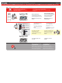
ADDENDUM - SUGGESTED WIRING CONFIGURATION
ADDENDA - SCHÉMA DE BRANCHEMENT SUGGÉRÉ
BYPASS FIRMWARE VERSION
VERSION LOGICIELLE CONTOURNEMENT
To add the rmware version and the options, use the
FLASH LINK UPDATER or FLASH LINK MOBILE tool,
sold separately.
Pour ajouter la version logicielle et les options,
utilisez l’outil FLASH LINK UPDATER
ou FLASH LINK MOBILE, vendu séparément.
71.[52]
FORD MINIMUM
Parts required (Not included) Pièce(s) requise(s) (Non incluse(s))
1x
3x
Relay (Parking lights)
Diodes 1Amp
Relais (Feux de stationnement)
Diode 1Amp
Program remote
starter option for R.S.
OEM REMOTE STAND
ALONE:
Programmez l’option
démarreur à distance
pour TÉLÉCOMMANDE
D’ORIGINE STAND
ALONE:
FUNCTION
FONCTION MODE DESCRIPTION
38 2
Enable
Press 3x Lock to remote start with the OEM remote.
Activé
Appuyez x3 sur Verrouille de la télécommance d’origine
pour démarrer à distance le véhicule.
Program bypass option:
Programmez l’option du contournement:
UNIT OPTION
OPTION UNITE DESCRIPTION
C1
OEM Remote status (Lock/Unlock)
monitoring
Suivi des status (Verrouillage/Déverrouil-
lage) de la télécommande d’origine
Program remote
starter option:
Programmez l’option
démarreur à distance:
FUNCTION
FONCTION MODE DESCRIPTION
82Double 0.25 sec unlock pulse
Double pulse unlock de 0.25 sec.
D5 Lock after start
Verrouillage après le démarrage
IF THE VEHICLE IS NOT EQUIPPED
WITH FUNCTIONAL HOOD PIN:
SI LE VÉHICULE N’EST PAS ÉQUIPÉ
D’UN CONTACT DE CAPOT FONCTIONNEL: A11 OFF
NON
Hood trigger (Output Status).
Contact de capot (état de sortie).
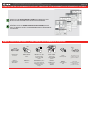
Vehicle functions supported in this diagram (functional if equipped) | Fonctions du véhicule supportées
dans ce diagramme (fonctionnelles si équipé)
Immobilizer bypass
Contournement
d’immobilisateur
T-Harness
Harnais en T
Lock
Unlock
Arm
Disarm
RAP Disable
Trunk Release
Parking Lights
Horn
Tachometer
Hood
Door Status
Trunk Status
Hood Status*
Hand-Brake Status
Foot-Brake Status
OEM Remote monitoring
R.S. OEM remote
Stand Alone compatible
VEHICLE
VEHICULES
YEARS
ANNÉES
FORD
Fiesta 2014-2019 • • •••••••••••••••• •
Guide # 72711
Parts required (Not included) Pièce(s) requise(s) (Non incluse(s))
1x
3x
1x
Relay (Parking lights)
Diodes 1Amp
THAR-FOR4
Relais (Feux de stationnement)
Diode 1Amp
THAR-FOR4
Page 1 / 8
THAR-FOR4 THARNESS INSTALLATION
INSTALLATION HARNAIS THAR-FOR4

This guide may change without notice. See www.fortin.ca for latest version.
Ce guide peut faire l’objet de changement sans préavis. Voir www.fortin.ca pour la récente version.
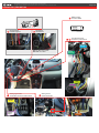
DESCRIPTION | DESCRIPTION
From Driver door boot
Caoutchouc provenant de la
porte conducteur
OBDII connector
Connecteur OBDII
RX and TX of the module
RX et TX du module
At ignition barrel
Au barillet d'ignition
Immobilisator
immobilisateur
DRIVER
DOOR PIN
(-)
DISARM
UNLOCK
LOCK
PARKING
LIGHTS
PARKING
LIGHTS
Parking Lights switch
Commutateur des feux de stationnement
(-)HORN
Steering column
Colonne de direction
Page 2 / 8

This guide may change without notice. See www.fortin.ca for latest version.
Ce guide peut faire l’objet de changement sans préavis. Voir www.fortin.ca pour la récente version.
DESCRIPTION | DESCRIPTION
12V BATTERY 12V BATTERIE
ATTENTION LE COURANT DU 12V PROVENANT DU
HARNAIS-EN-T EST LIMITÉ À 5 AMPÈRES
MAXIMUM.
Si les lumières de stationnement (+) requièrent plus de
5 Ampères, branchez le 12V du démarreur à distance
directement à la batterie du véhicule avec le fusible
approprié.
Certains démarreurs à distance NE peuvent PAS être
allimentés par le Data-Link. Dans ce cas, branchez le
12V (avec fusible) du démarreur à distance directement
au harnais-en-T.
ATTENTION
THE T-HARNESS CURRENT
IS LIMITED AT 5 AMP MAXIMUM.
If the parking lights (+) require more than 5Amp.
connect the remote-starter's power directly to the
vehicles battery with the appropriate fuse.
Some remote starters can not be powered through
Data-Link. In these cases connect the remote
starter's fused 12V power wire directly to the
T-Harness.
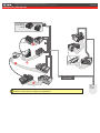
Make the connection between the UNIT and the T-HARNESS
Effectuez les branchements entre le MODULE et le HARNAIS EN T.
NOT CONNECTED
NE PAS BRANCHER
See next
page
Voir page
suivante
T-HARNESS - HARNAIS EN T
THAR-FORD4
4 PINS
6 PINS
B
A
Page 3 / 8

Yellow In A1
Purple Out A2
Purple/White Out A3
Green Out A4
White Out A5
Orange Out A6
Orange/Black Out A7
Dk.Blue Out A8
Red/Blue In A9
Lt.Blue/Black In/Out A10
Black In A11
Pink Out A12
Yellow/Black Out A13
Brown/White In A14
Pink/Black In A15
Purple/Yellow In/Out A16
Green/White In/Out A17
Green/Red In/Out A18
White/Black Out A19
Lt.Blue In/Out A20
C5 Brown
C4 Gray/Black
C3 Gray
C2 Orange/Brown
C1 Orange/Green
D6 White/Red
D5 White/Blue
D4 White/Green
D3 Yellow/Red
D2 Yellow/Blue
D1 Yellow/Green
White Out E1
Orange Out E2
Red In E3
Black In E4
Pink In/Out E5
Yellow Out E6
This guide may change without notice. See www.fortin.ca for latest version.
Ce guide peut faire l’objet de changement sans préavis. Voir www.fortin.ca pour la récente version.
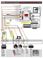
WIRING CONNECTION | GUIDE DE BRANCHEMENTS
(-) Hood pin
HOOD PIN
CONTACT CAPOT
CUT LOOP FOR AUTOMATIC
TRANSMISSION MODE.
COUPEZ LA BOUCLE POUR LE
MODE TRANSMISSION
AUTOMATIQUE.
(+)12V
(-)Trunk Release
(-)Parking Lights
(-)Horn
(-)Unlock
(+)Key sense
A2
A3
A4
A5
A6
A7
A8
A9
A10
A11
A12
A13
A14
A15
A16
A17
A18
A19
A20
E1
E2
E3
E4
E5
E6
C5
C4
C3
C2
C1
D6
D5
D4
D3
D2
D1
A1
D4
C1
C2
C5
E6
E5
E4
E2
E1
A14
A11
A9
A8
A6
A5
A4
A2
Fiesta
OPTIONAL
FACULTATIF
1
234567
8
10 9
111415
16 13 12
Green/
Purple
Vert/
Mauve
PARKING
LIGHTS (-)DRIVER
DOOR PIN
A17
CUT
A18
CUT
Yellow/Blue
Jaune/Bleu
PARKING
LIGHTS
White/Purple
Blanc/Mauve
(-)
DISARM
Blue/
Orange
Bleu/
Orange
123456
10 7
8
9
1415 13 12
11
123456
10 7
8
9
1415 13 12
11
(-)
UNLOCK
Purple/
Brown
Mauve/
Brun
(-)
LOCK
Yellow/
Lt.Grey
Jaune/
GrisPâle
From Driver door boot
Caoutchouc provenant de
la porte conducteur
Back View
- 16 pin
- Black connector
Vue de dos
- 16-pins
-Connecteur Noir
Back View
- 16 pin
- Grey connector
Vue de dos -
16-pins
-Connecteur Gris
Back View - 16
pin - Grey
connector -
Parking lights
switch.
Vue de dos -
16-pins-
Connecteur Gris
- Commutateur
des feux de
stationnement.
(-)TRUNK
RELEASE
Green/
White
Vert/
Blanc
Harness from
driver kick
Harnais
provenant du
panneau
latéral côté
conducteur.
A19
A3
A12
Connection
required to arm
the factory alarm
when the doors
are locked and
RAP Control.
Branchements
requis pour armer
l'alarme d'origine
lorsque les portes
sont verrouillées et
pour le contrôle du
RAP.
DRIVER DOOR PIN
DRIVER DOOR PIN
LOCK
A13
1A Diode
1A Diode
Brown
Brun
12345678
10 9111516 13 12
14
A7
(-)HORN
Back View
- 16 pin
- White
connector
- Steering
column
Vue de dos
- 16-pins
-Connecteur
Blanc
- Colonne de
direction
NOT CONNECTED | NE PAS BRANCHER
Yellow
Purple/Yellow
Orange/White
(+)IGNITION
KEY SENSE
IMMO POWER
NOT CONNECTED
NE PAS BRANCHER
T-HARNESS - HARNAIS EN T
THAR-FORD4
FUSE
FUSIBLE
REQUIRED WITH
(+)PARKING LIGHTS
REQUIS AVEC
(+)PARKING LIGHTS
If not used : Protect the main connector with
electrical tape to prevent shortcircuit to ground.
Si non u�lisé: Protégez le connecteur principal
avec du ruban électrique pour éviter les
cours-circuit avec la masse.
A1/RS6
NOT CONNECTED | NE PAS BRANCHER
A1/RS6
NOT CONNECTED | NE PAS BRANCHER
A1
Page 4 / 8

LOCK
ACC ON
PUSH
START
IGN
TURN
ON/RUN
Wait 3 seconds.
LOCK
ACC ON
START
IGN
ON
WAIT
3 SEC.
Attendre 3 secondes.
LOCK
ACC ON
PUSH
START
OFF
TURN
OFF
LOCK
ACC ON
START
PUSHPUSH
REMOVE
KEY
5
KEY#1
CLÉ#1
CONTINUED NEXT PAGE | CONTINUEZ À LA PAGE SUIVANTE
PROGRAMMING PROCEDURE | PROCÉDURE DE PROGRAMMATION
4
4
Release the programming
button when the LED is RED.
If the LED is not solid RED
disconnect the 6 Pin
connector (Main-Harness)
and go back to step 1.
Insert the required remaining
connectors.
CETTE PROGRAMMATION EST POUR LES
FORD 40BITS
1
2
3
RELEASE
A
E
F
GJ
I
H
B
C
D
ON RED
ROUGE
Insérez les connecteurs requis
restants.
Relâchez le bouton de
programmation quand la DEL
est ROUGE.
Si le DEL n'est pas ROUGE
solide débranchez le
connecteur 6 pins
(Connecteur principal) et allez
à l'étape 1.
A
E
F
GJ
I
H
B
C
D
A
E
F
GJ
I
H
B
C
D
A
E
F
GJ
I
H
B
C
D
A
E
F
GJ
I
H
B
C
D
A
E
F
GJ
I
H
B
C
D
KEY#2
CLÉ#2
KEY#1
CLÉ#1
2 KEY REQUIRED
2 CLÉS REQUISES
Choose between : Choisir entre:
KEY#1
CLÉ#1 KEY#2
CLÉ#2
KEY#1
CLÉ#1
2 key programming.
Programmation avec 2 clés.
DCRYPTOR and 1 key
programming.
Programmation avec
DCRYPTOR et 1 clé.
Tournez la première
clé fonctionelle à Ignition.
Turn the first functional key
to the Ignition ON/RUN
position.
Turn the key to the OFF
position.
Remove the first key.
Tournez la clé à la
position Arrêt (OFF).
Retirez la clé du contact.
x
x
1
1
HOLD
A
E
F
GJ
I
H
B
C
D
LED may differ depending on the module casing.
L’apparence des DELS peut dif
férer selon le boîtier du module.
Press and hold the
programming button:
Connect
the 6-PIN Main
harness (White connector).
The Blue, Red, Y
ellow and
Blue & Red LEDs will
alternatively illuminate.
Appuyez et maintenir le bouton
de programmation enfoncé:
Branchez
le harnais Principal à
6-Pins (connecteur Blanc)
Les DELs Bleue, Rouge,
Jaune et Bleue & Rouge
s'illumineront alternativement.
The module is now
programmed.
Le module est
programmé.
Use the remote of the remote
starter or security system to test
all of the supported features to
ensure proper programming.
Testez toutes les fonctions
supportées sur le véhicule avec la
télécommande du démarreur à
distance ou du système de sécurité.
8
xx11
PRESS
RELEASE
A
E
F
GJ
I
H
B
C
D
Press and hold the
programming button until
the vehicle ignition turn
ON.
Pesez et garder appuyé
le bouton de
programmation jusqu'à ce
que l'ignition du véhicule
s'allume.
Release the
programming button.
Relâchez le bouton de
programmation.
Ignition ON
HOLD
The RED LED will flash
rapidly 10x times.
The BLUE LED will flash
rapidly.
Key bypass programmed.
CAN-Bus programmed.
La DEL ROUGE clignotera
10x fois rapidement.
La DEL BLEU clignotera
rapidement:
Contournement de clé
programmé.
Réseau CAN programmé.
A
E
F
GJ
I
H
B
C
D
FLASH 10X
IGNITION ON
FLASH 10X
FLASH
If the LED is solid RED
disconnect the 4 Pin
connector (Data-Link) and go
back to step 1.
Si le DEL est ROUGE solide
débranchez le connecteur 4
pins (Data-Link) et allez à
l'étape 1.
A
E
F
GJ
I
H
B
C
D
6
LOCK
ACC ON
PUSH
START
IGN
TURN
ON/RUN
Wait 3 seconds. Attendre 3 secondes.
KEY#2
CLÉ#2
LOCK
ACC ON
PUSH
START
OFF
TURN
OFF
7
LOCK
ACC ON
START
PUSHPUSH
REMOVE
KEY
LOCK
ACC ON
START
IGN
ON
WAIT
3 SEC.
The vehicle ignition will
turn OFF.
L'ignition du véhicule
s'éteins.
Ignition OFF
5 sec. max
CAUTION The following step must
be completed within 5 seconds.
Otherwise disconnect all connectors
and go back to step 1.
ATTENTION les prochaines étapes doivent être
complétées en moins de 5 secondes.
Si non, débranchez tous les connecteurs et allez
à l'étape 1.
9
5 sec. max
CAUTION The following step must
be completed within 5 seconds.
Otherwise disconnect all connectors
and go back to step 1.
ATTENTION les prochaines étapes doivent être
complétées en moins de 5 secondes.
Si non, débranchez tous les connecteurs et allez
à l'étape 1.
Press the driver door
Lock button.
Appuyez sur le bouton
Verrouillage de la porte
côté conducteur.
Tournez la deuxième
clé fonctionelle à Ignition.
Turn the second functional
key to the Ignition ON/RUN
position.
Turn the key to the OFF
position.
Remove the second key.
Tournez la clé à la
position
Arrêt (OFF)
Retirez
la deuxième clé
du barillet d'alimentation.
LOCK
ACC ON
PUSH
START
IGN
TURN
ON/RUN
Wait 3 seconds.
LOCK
ACC ON
START
IGN
ON
WAIT
3 SEC.
Attendre 3 secondes.
LOCK
ACC ON
PUSH
START
OFF
TURN
OFF
LOCK
ACC ON
START
PUSHPUSH
REMOVE
KEY
5
KEY#1
CLÉ#1
CONTINUED NEXT PAGE | CONTINUEZ À LA PAGE SUIVANTE
PROGRAMMING PROCEDURE | PROCÉDURE DE PROGRAMMATION
44
Release the programming
button when the LED is RED.
If the LED is not solid RED
disconnect the 6 Pin
connector (Main-Harness)
and go back to step 1.
Insert the required remaining
connectors.
CETTE PROGRAMMATION EST POUR LES
FORD 40BITS
1
2
3
RELEASE
A
E
F
GJ
I
H
B
C
D
ON RED
ROUGE
Insérez les connecteurs requis
restants.
Relâchez le bouton de
programmation quand la DEL
est ROUGE.
Si le DEL n'est pas ROUGE
solide débranchez le
connecteur 6 pins
(Connecteur principal) et allez
à l'étape 1.
A
E
F
GJ
I
H
B
C
D
A
E
F
GJ
I
H
B
C
D
A
E
F
GJ
I
H
B
C
D
A
E
F
GJ
I
H
B
C
D
A
E
F
GJ
I
H
B
C
D
KEY#2
CLÉ#2
KEY#1
CLÉ#1
2 KEY REQUIRED
2 CLÉS REQUISES
Choose between : Choisir entre:
KEY#1
CLÉ#1 KEY#2
CLÉ#2
KEY#1
CLÉ#1
2 key programming.
Programmation avec 2 clés.
DCRYPTOR and 1 key
programming.
Programmation avec
DCRYPTOR et 1 clé.
Tournez la première
clé fonctionelle à Ignition.
Turn the first functional key
to the Ignition ON/RUN
position.
Turn the key to the OFF
position.
Remove the first key.
Tournez la clé à la
position Arrêt (OFF).
Retirez la clé du contact.
xx11
HOLD
A
E
F
GJ
I
H
B
C
D
LED may differ depending on the module casing.
L’apparence des DELS peut différer selon le boîtier du module.
Press and hold the
programming button:
Connect the 6-PIN Main
harness (White connector).
The Blue, Red, Yellow and
Blue & Red LEDs will
alternatively illuminate.
Appuyez et maintenir le bouton
de programmation enfoncé:
Branchez le harnais Principal à
6-Pins (connecteur Blanc)
Les DELs Bleue, Rouge,
Jaune et Bleue & Rouge
s'illumineront alternativement.
This guide may change without notice. See www.fortin.ca for latest version.
Ce guide peut faire l’objet de changement sans préavis. Voir www.fortin.ca pour la récente version.
KEY BYPASS PROGRAMMING PROCEDURE 1/2 | PROCÉDURE DE PROGRAMMATION CONTOURNEMENT DE CLÉ 1/2
1
2
3
1
Connect the required
remaining harnesses.
Branchez les harnais
requis restants.
The Blue, Red, Yellow
and Blue & Red LEDs will
alternatively illuminate.
Les DELs Bleue, Rouge,
Jaune et Bleue & Rouge
illumineront alternativement.
Press and hold the
programming button:
Connect the 4-PIN Data-link
harness (Black connector).
Appuyez et maintenir le bouton
de programmation enfoncé:
Branchez le harnais Data-Link à
4-Broches (connecteur Noir)
x1
HOLD
A
E
F
G
J
I
H
B
C
D
A
E
F
G
J
I
H
B
C
D
A
E
F
G
J
I
H
B
C
D
A
E
F
G
J
I
H
B
C
D
A
E
F
G
J
I
H
B
C
D
The Blue, Red, Yellow
and Blue & Red LEDs will
alternatively illuminate.
Les DELs Bleue, Rouge,
Jaune et Bleue & Rouge
illumineront alternativement.
A
E
F
G
J
I
H
B
C
D
A
E
F
G
J
I
H
B
C
D
RELEASE
ON BLUE
BLEU
ON RED
ROUGE
If the LED are not solid BLUE
and RED disconnect the 4-PIN
Data-link harness (Black
connector).
Si les DELs Bleue & Rouge ne
sont pas allumées, débranchez le
harnais Data-Link à 4-Broches
(connecteur Noir).
A
E
F
G
J
I
H
B
C
D
Release the programming
button when the Blue & Red
LEDs are ON.
Relâchez le bouton de program-
mation quand les DELs Bleue &
Rouge sont allumées.
Page 5 / 8

8
Press and hold the
programming button until
the vehicle ignition turn ON.
Pesez et gardez appuyé
le bouton de programmation
Jusqu’à ce que l'ignition
du véhicule s'allume.
Release the programming
button. Relâchez le bouton de
programmation.
Ignition ON
The RED LED will flash
rapidly 10x times.
The BLUE LED will flash
rapidly.
Key bypass programmed.
CAN-Bus programmed.
La DEL ROUGE clignotera
10x fois rapidement.
La DEL BLEU clignotera
rapidement:
Contournement de clé
programmé.
Réseau CAN programmé.
6
7
5 sec. max
CAUTION The following step must
be completed within 5 seconds.
Otherwise disconnect all connectors
and go back to step 1.
ATTENTION
5 secondes.
débranchez allez
les prochaines étapes doivent être
complétées en moinsde
Si non, tous les connecteurs et
àl'étape 1.
Wait 3 seconds. Attendre 3 secondes.
x1
PRESS
HOLD
RELEASE
The module is now
programmed.
Le module est
programmé.
Use the remote of the remote
starter or security system to test
all of the supported features to
ensure proper programming.
Testez toutes les fonctions
supportées sur le véhicule avec la
télécommande du démarreur à
distance ou du système de sécurité.
The vehicle ignition will
turn OFF.
L'ignition du véhicule
s'éteins.
Ignition OFF
A
E
F
G
J
I
H
B
C
D
A
E
F
G
J
I
H
B
C
D
FLASH 10X
IGNITIONON
FLASH 10X
FLASH
If the LED is solid RED
disconnect the 4 Pin
connector (Data-Link) and go
back to step 1.
Si le DEL est ROUGE solide
débranchez le connecteur 4
pins (Data-Link) et allez à
l'étape 1.
A
E
F
G
J
I
H
B
C
D
FLASH 10X
ON
x2
OFF
x1 Press and release the
Push-to-Start button once to shut
off the ignition.
Press and release the
Push-to-Start button twice to turn
ON the ignition.
Appuyez et relâchez 1 fois sur le
bouton démarrage
(Push-to-Start) pour éteindre
l'ignition.
Appuyez et relâchez 2 fois sur le
bouton démarrage
(Push-to-Start) pour allumer
l'ignition.
5-Prog.4-3-3keys
This guide may change without notice. See www.fortin.ca for latest version.
Ce guide peut faire l’objet de changement sans préavis. Voir www.fortin.ca pour la récente version.
KEY BYPASS PROGRAMMING PROCEDURE 2/2 | PROCÉDURE DE PROGRAMMATION CONTOURNEMENT DE CLÉ 2/2
Page 6 / 8

This guide may change without notice. See www.fortin.ca for latest version.
Ce guide peut faire l’objet de changement sans préavis. Voir www.fortin.ca pour la récente version.
REMOTE STARTER PROGRAMMING PROCEDURE | PROCÉDURE DE PROGRAMMATION DU DÉMARREUR À DISTANCE
REFER TO THE QUICK INSTALL GUIDE INCLUDED WITH THE
MODULE FOR THE REMOTE STARTER PROGRAMMING.
RÉFÉREZ-VOUS AU GUIDE D’INSTALLATION RAPIDE INCLUS
AVEC LE MODULE POUR LA PROGRAMMATION DU DÉMARREUR
À DISTANCE.
REMOTE STARTER FUNCTIONALITY | FONCTIONNALITÉS DU DÉMARREUR À DISTANCE
Remote start the
vehicle.
Démarrez à
distance.
All doors must
be closed.
Toutes les
portes doivent
être fermées.
Start
UNLOCK
Unlock the doors with
the remote-starter
remote or the OEM
remote.
Déverrouillez les portes
avec la télécomande du
démarreur à distance ou
la télécommande
d'origine.
Insert and Turn
the key to the
Ignition ON/RUN
position.
Insérez et
tournez la clé à
la position
"ON/RUN".
The vehicle can
now be put in to
gear and driven.
Vous êtes
maintenant prêt à
embrayer et
prendre la route.
Press
the brake pedal.
Appuyez
sur la pédale de
frein.
ON
TURN
ON/RUN
Page 7 / 8

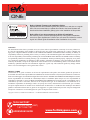
Service No : 000 102 04 2536
Date: xx-xx
INTERFACE MODULE
Made in Canada
PATENTS PENDING US: 2007-228827-A1
www.fortinbypass.com
HARDWARE VERSION
FIRMWARE VERSION
Module label | Étiquette sur le module
Notice: Updated Firmware and Installation Guides
Updated fi rmware and installation guides are posted on our web site on a regular
basis. We recommend that you update this module to the latest fi rmware and
download the latest installation guide(s) prior to the installation of this product.
Notice: Mise à jour microprogramme et Guides d’installations
Des mises à jour du Firmware (microprogramme) et des guides d’installation
sont mis en ligne régulièrement. Vérifi ez que vous avez bien la dernière version
logiciel et le dernier guide d’installation avant l’installation de ce produit.
WARNING
The information on this sheet is provided on an (as is) basis with no representation or warranty of accuracy whatsoever.
It is the sole responsibility of the installer to check and verify any circuit before connecting to it. Only a computer safe
logic probe or digital multimeter should be used. FORTIN ELECTRONIC SYSTEMS assumes absolutely no liability or
responsibility whatsoever pertaining to the accuracy or currency of the information supplied. The installation in every case
is the sole responsibility of the installer performing the work and FORTIN ELECTRONIC SYSTEMS assumes no liability
or responsibility whatsoever resulting from any type of installation, whether performed properly, improperly or any other
way. Neither the manufacturer or distributor of this module is responsible of damages of any kind indirectly or directly
caused by this module, except for the replacement of this module in case of manufacturing defects. This module must be
installed by qualifi ed technician. The information supplied is a guide only. This instruction guide may change without
notice. Visit www.fortinbypass.com to get the latest version.
MISE EN GARDE
L’information de ce guide est fournie sur la base de représentation (telle quelle) sans aucune garantie de précision et
d’exactitude. Il est de la seule responsabilité de l’installateur de vérifi er tous les fi ls et circuits avant d’effectuer les connexions.
Seuls une sonde logique ou un multimètre digital doivent être utilisés. FORTIN SYSTÈMES ÉLECTRONIQUES n’assume
aucune responsabilité de l’exactitude de l’information fournie. L’installation (dans chaque cas) est la responsabilité de
l’installateur effectuant le travail. FORTIN SYSTÈMES ÉLECTRONIQUES n’assume aucune responsabilité suite à
l’installation, que celle-ci soit bonne, mauvaise ou de n’importe autre type. Ni le manufacturier, ni le distributeur ne se
considèrent responsables des dommages causés ou ayant pu être causés, indirectement ou directement, par ce module,
excepté le remplacement de ce module en cas de défectuosité de fabrication. Ce module doit être installé par un technicien
qualifi é. L’information fournie dans ce guide est une suggestion. Ce guide d’instruction peut faire l’objet de changement
sans préavis. Consultez le www.fortinbypass.com pour voir la plus récente version.
Copyright © 2006-2018, FORTIN AUTO RADIO INC ALL RIGHTS RESERVED PATENT PENDING
TECH SUPPORT
Tél: 514-255-HELP (4357)
1-877-336-7797
ADDENDUM GUIDE WEB UPDATE | MISE À JOUR INTERNET
www.fortinbypass.com
ONE
Page 8 / 8
-
 1
1
-
 2
2
-
 3
3
-
 4
4
-
 5
5
-
 6
6
-
 7
7
-
 8
8


dans d''autres langues
- English: Fortin 2017 Installation guide
Documents connexes
-
Fortin 95191 Guide d'installation
-
-
Fortin 94911 Guide d'installation
-
Fortin 94791 Guide d'installation
-
Fortin 94851 Guide d'installation
-
Fortin 92011 Guide d'installation
-
-
Fortin 80711 Guide d'installation
-
Fortin Honda Civic 2020 Guide d'installation
-
Fortin 2021 Guide d'installation