
Installation Guide
Read and Save These Instructions
Watch the installation video at:
reventfans.com/install
Questions? Call
1-877-543-8698 (English) or
1-800-615-5439 (French)
model
RVM80
Need Help?
English

1
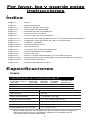
Table of Contents
Please Read and Save
These Instructions
RVM80
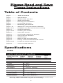
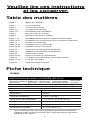
Specifications
Voltage
Frequency
Fan Weight
Shield Size
Housing Length*
Housing Width*
Housing Depth*
120 V
60 Hz
7.8 Lbs ( 3.54 Kg )
11 x 11 in ( 27.9 x 27.9 cm )
8 3/8 in ( 21.3 cm )
7 7/8 in ( 20 cm )
6 3/8 in ( 16.2 cm )
*This may require modification of your current opening. Some hand
tools required. Power tools may also be necessary.
performance at 4" ducting
Duct
Size
4 in
4 in
Energy
(watts)
20.5
20.2
Static Pressure
(in wg)
0.1
0.25
Airow
(cfm)
80
63
Sound
(sones)
0.9
page 1
page 1
page 2
page 3
page 4
page 5
page 6
page 7-12
page 12-17
page 17
page 18-20
page 21
page 21
page 22
page 22
page 23
page 23
page 24-25
page 26
Table of Contents
Specifications
What’s Inside The Box
Safety Information
Planning Your Installation
Connecting The Duct
Removing Your Old Fan
SheetLock® Easy Roomside Installation
Installation For New Construction Framing
Care And Cleaning
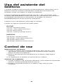
Installing The Control
Using The Control
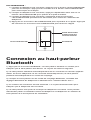
Connecting to Bluetooth Speaker
Using Phone’s Assistant
Voice Control
Make or Take a Call and Text
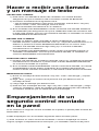
Pairing a Second Wall Mounted Control
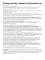
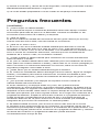
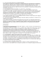
Frequently Asked Questions
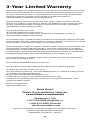
3-Year Limited Warranty
...............
...............
...............
...............
...............
...............
...............
..........
........
.............
........
.............
.............
.............
.............
.............
.............
........
.............

2
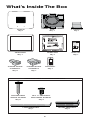
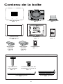
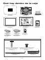
What’s Inside The Box
MANUAL
Qty:1
TEMPLATE
Qty:1
TRIM RING
Qty:1
FAN
Qty:1
4” DAMPER
Qty:1
SHIELD
Qty:1
SHORT BRACKET
Qty:2
LONG BRACKET
Qty:1
2-WIRE QUICK
CONNECT
Qty:2
3-WIRE QUICK
CONNECT
Qty:1
ROUNDHEAD
WOOD SCREW
Qty:6
#8 x 3/8" BRACKET
SECURING SCREW
Qty:3
USED FOR NEW CONSTRUCTION ONLY
CONTROL
Qty:1
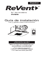
Installation Guide
Read and Save These Instructions
Watch the installation video at:
reventfans.com/install
Questions? Call
1-877-543-8698 (English) or
1-800-615-5439 (French)
model
RVM80
Need Help?
English

3
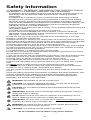
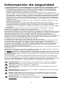
Safety Information
1.) WARNING - TO REDUCE THE RISK OF FIRE, ELECTRIC SHOCK,
OR INJURY TO PERSONS, OBSERVE THE FOLLOWING:
a) Installation work and electrical wiring must be done by qualified person(s) in
accordance with all applicable codes and standards, including fire-rated
construction.
b) Sufficient air is needed for proper combustion and exhausting of gases
through the flue (chimney) of fuel burning equipment to prevent back drafting.
Follow the heating equipment manufacturer's guideline and safety standards,
such as those published by the National Fire Protection Association (NFPA), the
American Society for Heating, Refrigeration and Air Conditioning Engineers
(ASHRAE), and the local code authorities.
c) When cutting or drilling into wall or ceiling, do not damage electrical wiring and
other hidden utilities.
d) Ducted fans must always be vented to the outdoors.
e) If this unit is to be installed over a tub or shower, it must be marked as
appropriate for the application and be connected to a GFCI (Ground Fault Circuit
Interrupter) - protected branch circuit.
2.) Use this unit only in the manner intended by the manufacturer. If you have
questions, contact the manufacturer.
3.) Before servicing or cleaning unit, switch power off at service panel and lock the
service disconnecting means to prevent power from being switched on accidentally.
When the service disconnecting means cannot be locked, securely fasten a
prominent warning device, such as a tag, to the service panel.
4.) This ventilation fan is approved for use over a bathtub or shower when installed
in a GFCI protected circuit. Do not use unapproved fans over a bathtub or shower
that are not approved for that application.
5.) Install ductwork in a straight line with minimal bends.
6.) Use 120 V, 60 Hz for the electrical supply and properly ground the unit. Follow
all local safety and electrical codes.
7.) Do not use this fan with any solid-state control device; such as a dimmer switch.
Solid-state controls may cause harmonic distortion, which can cause a motor
humming noise, as well as increase risk of fire or electric shock.
8.) To reduce the risk of fire or electric shock, do not block air entry shield.
9.) Mount with the lowest moving parts at least 8.2 ft (2.5 m) above floor or grade
level.
10.) Never place a switch where it can be reached from a tub or shower.
11.) Type IC for use in direct contact with thermal insulation not to exceed R-50.
12.) Not for use in cooking areas. (See PAGE 5 for details)
13.) This product must properly connect to the grounding conductor of the supply
circuit.
Follow the heating equipment manufacturer’s guideline and safety standards, such
as those published by the National Fire Protection Association (NFPA), the
American Society for Heating, Refrigeration and Air Conditioning Engineers
(ASHRAE), and the local code authorities.
WARNING: Not suitable for use as a range hood.
CAUTION: For General Ventilating Use Only - Do Not Use To Exhaust
Hazardous Or Explosive Materials And Vapors.
CAUTION: Do not install in locations where the temperature will exceed
104°F (40°C).
IMPORTANT: Exercise care to not damage existing wiring when cutting or
drilling into walls or ceilings.
NOTE: Make sure duct work size is a minimum of the discharge. Do not
reduce. Reducing the duct size can increase fan noise.
IMPORTANT: You may want to consult with a qualified licensed electrician
regarding the wiring of your ventilation fan.
WARNING: To reduce the risk of electric shock, please disconnect the
electrical supply circuit before servicing.
CAUTION: This product must be properly grounded.
Go to reventfans.com to obtain a copy of this manual.

4
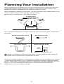
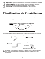
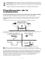
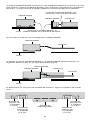
NOTE: If installing in existing construction, you may need to have access to
space above and below the installation location.
Cooking Area
do not install above or
inside this area
Cooking
Equipment Floor
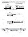
Turning angle too sharp
Too many elbows
Avoid duct shrink
Elbow near the body
Fan
Body
Minimum 18 in ( 45.72 cm )
Planning Your Installation
When installing the ventilation fan in a new construction site, install the main body
of the FAN and duct work during the rough-in construction of the building. The
SHIELD should be installed after the finished ceiling is in place.
When installing in existing construction, use the provided cutout TEMPLATE for the
ceiling. SHIELD edge should overlap finished ceiling.
Not for use in cooking area - see diagram below.
Do not install ventilation fan in areas where the duct work will require configuration
as shown.
There are multiple installation configurations possible for this ventilation fan. Not all
configurations are shown. If your installation requires a variation other than those
shown, consult with a licensed contractor to determine the best installation for your
project. If you are replacing an existing fan, ensure that the new FAN will
adequately cover the existing opening.

5
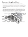
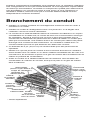
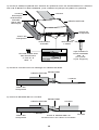
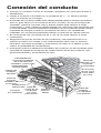
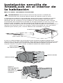
Connecting the Duct
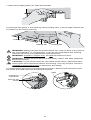
● Install a circular duct to outlet and secure it with duct tape or clamps.
● Install the duct to the outlet with a gradient 1°~2° to the outside as shown.
● The ducting from this FAN to the outside of the building has a strong effect on
● the air flow, noise and energy use of the fan. Use the shortest, straightest duct
● routing possible for best performance, and avoid installing the FAN with smaller
● ducts than recommended. Insulation around the ducts can reduce energy loss
● and inhibit mold growth. Fans installed with existing ducts may not achieve their
● rated airflow.
● 4 in (10.16 cm) round is recommended for best performance.
● Ensure duct joints and exterior penetrations are sealed with caulk or other
● similar material to create an air-tight path, to minimize building heat loss and
● gain, and to reduce the potential for condensation.
● Place/wrap insulation around duct and/or FAN in order to minimize possible
● condensation buildup within the duct, building heat loss and gain.
INSULATION*
(Place around and
over Fan Housing.)
Seal gaps
around
housing.
ROUND
DUCT*
POWER
CABLE*
Seal duct
joints with
tape.
FAN
HOUSING
ROUND
ELBOWS*
ROOF CAP*
(with built-in
damper)
Keep duct
runs short.
WALL CAP*
(with built-in
damper)
*Purchase
separately.
OR

6
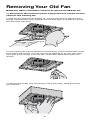
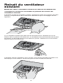
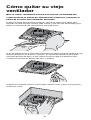
Removing Your Old Fan
Watch the video: reventfans.com/how-to-remove-an-old-bath-fan
1.) Disconnect the electrical power supply and lock out the service
panel for the existing fan.
2.) Remove the grille from the existing fan. Pull the grille down to expose it’s two
springs. Squeeze each spring together and pull down again to release the springs
from the motor plate slots.
3.) Your existing fan may be attached in several ways. Look for attachment screws
in the ceiling and remove. Your fan may also be attached on the attic side, which
will require you to access it from the attic. Locate attic attachment screws and
remove.
4.) Remove the old fan. This may require cutting and pulling. Wear gloves and
eye protection.

7
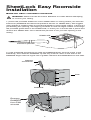
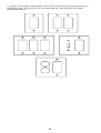
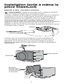
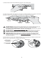
1.) Place the provided sheetrock cutout TEMPLATE on ceiling where you wish the
FAN to be (DAMPER and electrical positions shown on TEMPLATE). We suggest
using painter’s masking tape to hold the template in place while cutting. If there is a
pre-existing fan opening, use aligning windows to find it’s edges. Either cut through
the provided guide slots in the TEMPLATE, or mark your cut lines with a pencil and
remove the TEMPLATE. Use a sheetrock jab saw to cut your fan opening in the
ceiling.
SheetLock® Easy Roomside
Installation
Watch the video: reventfans.com/install
WARNING: Disconnect all AC Power Breakers or Fuses before attempting
to cut into your ceiling.
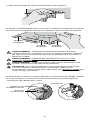
2.) Use a flathead screwdriver to raise the DAMPER away from the notch in the
FAN body, then slide the DAMPER up half way until the notch in the side of the
DAMPER aligns with the upper set of guides. Remove the DAMPER from the FAN.
Remove
DAMPER
from FAN
at notch
flathead
screwdriver
FAN
DAMPER
notch
guide
TEMPLATE
sheetrock jab saw
guide

8
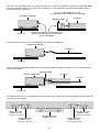
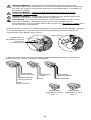
4.) Attach conduit with wiring to FAN.
conduit
FAN
6.) Select a set of holding tabs, depending on the thickness of your sheetrock.
5/8 in (1.6 cm)
holding tab
1/2 in (1.3 cm)
holding tab
final securing tab 5/8 in (1.6 cm)
holding tab
1/2 in (1.3 cm)
holding tab
5.) Reattach DAMPER to FAN inside the ceiling, damper should click into place
securely.
ducting
conduit
DAMPER
FAN
3.) Attach DAMPER to ducting. Tape DAMPER to ducting with duct tape. Set the
connected DAMPER and ducting in the ceiling opening, then set the FAN in the
ceiling opening as well.
ceiling
ducting
Connect DAMPER and
ducting with duct tape
Place FAN and DAMPER
inside CEILING opening
ceiling
ceiling
FAN
DAMPER

9
7.) Bend the holding tabs you selected outward.
9.) Disconnect FAN motor from electrical enclosure. Remove the electrical cover
set screw and slide open the electrical enclosure.
remove set
screw
unplug fan
connector
slide
WARNING: Disconnect the AC power before any work is done to any part of
the circuit ReVent® is connected to. If you do not understand this warning,
seek the services of a qualified licensed electrician.
WARNING: Copper to copper only. Do not use aluminum wire.
WARNING: Follow all local electrical and safety codes, and NEC (National
Electrical Codes).
CAUTION: If your house wires do not match these colors, determine what
each house wire represents before connecting. You may need to consult a
qualified licensed electrician to determine this safely.
8.) Set FAN into place in the opening using holding tabs, now the tabs hold the fan
in position in the ceiling opening.
holding tab
holding tab
holding tab

10
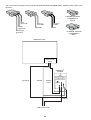
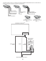
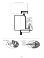
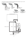
10.) Connect wiring using the provided QUICK CONNECTS. Match wire colors as
shown:
2-WIRE QUICK
CONNECT
Qty:2
3-WIRE QUICK
CONNECT
Qty:1
line
ground
FAN
ground
housing
ground
line in
neutral
neutral
line in
FAN
FAN
ReVent® fan
ReVent®
switch
120V line AC
black
/red
white
ground
fan’s
electrical
box
black
ReVent® FSM-80
product of GTR Technologies Inc.
USA and international patents pending.
Electrical Input: 120 volts @ 60Hz
Maximum Fan Load: 6 Amps
This switch is only to be used with
ReVent fan model RVM80
Must Be Mounted Inside A Code
Approved Electrical Outlet Box
Made In China

11
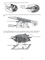
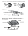
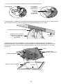
12.) Press and bend the final securing tabs flat against ceiling to lock the FAN in
place.
final securing tabs
13.) Align TRIM RING notch to vent (DAMPER) position. Attach TRIM RING to
FAN. TRIM RING attaches to FAN body and clicks into place when secure.
sheetrock
(ceiling)
apply even
pressure to
each side of
securing tab
11.) Once connected, reattach the electrical enclosure.
reattach set
screw
plug in fan
connector
slide
ceiling
TRIM RING
FAN
final securing tabs
notch

12
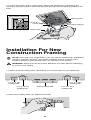
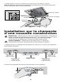
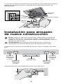
Installation For New
Construction Framing
WARNING: Disconnect all AC Power Breakers or Fuses before attempting
to cut into your ceiling.
1.) Select a set of holding tabs, depending on the thickness of your sheetrock.
2.) Bend the holding tabs you selected outward.
5/8 in (1.6 cm)
holding tab
1/2 in (1.3 cm)
holding tab
final securing tab 5/8 in (1.6 cm)
holding tab
1/2 in (1.3 cm)
holding tab
NOTE: Even with new construction, you can use the SheetLock® installation
method; however, ReVent® can still be installed using a method home
builders would be more familiar with, as outlined in this section.
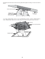
14.) Connect music wire to music plug. Attach the SHIELD by squeezing the
mounting springs together and inserting the springs into the spring guides in the
FAN.
mounting springs
spring guide
music wire
music plug

13
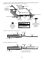
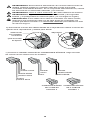
4.) Attach conduit with wiring to FAN.
conduit
DAMPERFAN
DAMPERFAN
5.) Attach DAMPER to ducting.
Attach DAMPER to
ducting with duct tape
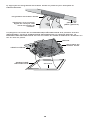
framing joist
framing joist
FAN
SHORT
BRACKET
(can be
cut down)
framing joist
framing joist
SHORT
BRACKET LONG
BRACKET
conduit
3.) Attach FAN to ceiling joists with BRACKETS using ROUNDHEAD WOOD
SCREWS, then install the sheetrock for your ceiling.
ducting
ducting
#8 x 3/8"
BRACKET
SECURING
SCREW
Qty:3
conduit
ROUNDHEAD
WOOD SCREW
Qty:6
(use 2 per
bracket)

14
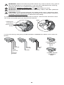
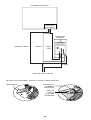
6.) Disconnect FAN motor from electrical enclosure. Remove the electrical cover
set screw and slide open the electrical enclosure.
remove set
screw
unplug fan
connector
slide
WARNING: Disconnect the AC power before any work is done to any part of
the circuit ReVent® is connected to. If you do not understand this warning,
seek the services of a qualified licensed electrician.
WARNING: Copper to copper only. Do not use aluminum wire.
WARNING: Follow all local electrical and safety codes, and NEC (National
Electrical Codes).
CAUTION: If your house wires do not match these colors, determine what
each house wire represents before connecting. You may need to consult a
qualified licensed electrician to determine this safely.
7.) Connect wiring using the provided QUICK CONNECTS. Match wire colors as
shown:
2-WIRE QUICK
CONNECT
Qty:2
3-WIRE QUICK
CONNECT
Qty:1
line
ground
FAN
ground
housing
ground
line in
neutral
neutral
line in
FAN
FAN

15
8.) Once connected, reattach the electrical enclosure.
reattach set
screw
plug in fan
connector
slide
ReVent® fan
ReVent®
switch
120V line AC
black
/red
white
ground
fan’s
electrical
box
black
ReVent® FSM-80
product of GTR Technologies Inc.
USA and international patents pending.
Electrical Input: 120 volts @ 60Hz
Maximum Fan Load: 6 Amps
This switch is only to be used with
ReVent fan model RVM80
Must Be Mounted Inside A Code
Approved Electrical Outlet Box
Made In China

16
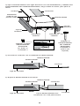
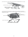
9.) Press and bend the final securing tabs flat against ceiling to lock the FAN in
place.
final securing tabs
sheetrock
(ceiling)
apply even
pressure to
each side of
securing tab
10.) Align TRIM RING notch to vent (DAMPER) position. Attach TRIM RING to
FAN. TRIM RING attaches to FAN body and clicks into place when secure.
ceiling
TRIM RING
FAN
final securing tabs
notch

17
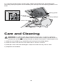
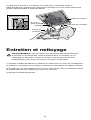
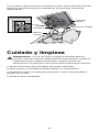
Care and Cleaning
WARNING: To reduce the risk of electric shock, fire, or injury to persons,
disconnect or turn off the breaker and lock the power supply at the panel to
prevent the power from being turned on before servicing or cleaning the unit.
1.) Remove the SHIELD by squeezing the springs and pulling down.
2.) Remove dust and dirt from the FAN with a vacuum cleaner.
3.) Dampen cloth with dish detergent. Wipe the FAN and dry with a cloth.
4.) Replace the SHIELD.
11.) Connect music wire to music plug. Attach the SHIELD by squeezing the
mounting springs together and inserting the springs into the spring guides in the
FAN.
mounting springs
spring guide
music wire
music plug

18
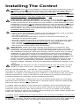
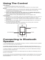
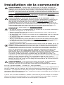
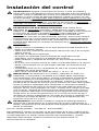
Installing The Control
WARNING: Turn off circuit breaker or remove fuse(s) and test that power is
off before wiring. Wiring the control live can cause serious risk of electrical
shock and/or damage the control, voiding the warranty. For safety, this
product must be installed in a grounded wall enclosure. If you are unfamiliar
with methods of installing electrical wiring, secure the services of a qualified
licensed electrician. Use only copper wire, do not use aluminum wire with
this device.
ELECTRICAL SHOCK WARNING: This control is an automatic on device.
At no time should a person work on the fan/light or any appliance connected
to this control without the electrical circuit breaker or fuse switched off. This
CONTROL could turn on the attached device by the unintended presence of
condensation while the work is being performed. Always disconnect the AC
power before any work is done to any part of the circuit this CONTROL is
connected to. If you do not understand this warning, seek the services of a
qualified licensed electrician.
CAUTION:
• Never place the CONTROL where it can be reached from a tub or shower.
• Use only a 120V AC 60Hz power supply connection.
• For indoor use only.
• Do not exceed the CONTROL’s maximum electrical load ratings, as
• indicated on the product label.
• Must be installed and used in accordance with your local electrical codes.
• If a bare copper or green ground connection is not available in the wall
• box, contact a qualified licensed electrician for installation.
• For use with permanently installed 120V AC powered fans only.
• Use only #14 or #12 copper wire connections.
IMPORTANT: Read each step carefully and perform in sequence. The
CONTROL will not work or will become damaged if wires are connected
incorrectly. To prevent damage, connect the CONTROL exactly as shown in
the installation diagrams, otherwise warranty will be voided. Prior to wiring,
straighten or clip ends of wire such that ends of each wire are straight (if
using the CONTROL to replace an existing switch). Strip wire insulation at
the end of each wire to expose 16 mm (0.63 in) of copper. Where instructed
to make a connection, twist ends of stripped wires together and twist a
proper connector clockwise until secure. The Operating Control is a Type 1
Action Control, Independently Mounted, Pollution Degree 2, tested to an
impulse voltage of 2500V, and has an Operating Temperature Range of 0°C
- 40°C.
WARNING: To avoid fire or risk of electrical shock, turn off power at circuit
breaker or disconnect fuse. Test the power is off before you begin wiring.
FCC ID: 2AHXP-RVM80 Canada IC : 21435-RVM80
This device complies with Part 15 of the FCC Rules and RSS-210 of Canada.
Operation is subject to the following two conditions: (1) this device may not cause
harmful interference, and (2) this device must accept any interference received,
including interference that may cause undesired operation.
1.) For new installations, install a 8.9 cm (3.5 in) deep single-gang or multi-gang
electrical wall enclosure, or (replacement of existing switch) remove existing wall
plate and switch device being replaced.
2.) Attach 120V AC 60Hz 3-wire power (Hot / Neutral / Ground) inside the wall
enclosure with a minimum of 15.2 cm (6 in) leads. Attach fan three wire leads
inside the wall enclosure also with minimum 15.2 cm (6 in) leads. If an existing
power connection is used in an existing wall enclosure you must confirm proper AC
120V Hot / Neutral / Ground are available.
3.) Attach wires. Make sure the wall enclosure, fan, and the CONTROL are properly
grounded. Make sure ground wire is securely fastened. Tighten all ground screws
or wire nuts securely. Use the proper sized wire nut for #14 or #12 wire. Make sure
to strip back the copper wire 1.6 cm (5/8 in) and twist wire and nut clockwise.

19
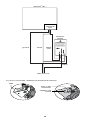
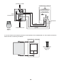
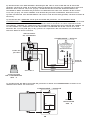
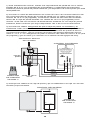
4.) Tuck wires into wall enclosure and fasten the CONTROL to the wall enclosure
with the two screws provided.
power to fan
ground
120V line AC
CONTROL BACK
wall
enclosure
MOUNTING
SCREW
Qty:2
WIRE
NUT
Qty:4
MUSIC
FAN
ReVent® FSM-80
product of GTR Technologies Inc.
USA and international patents pending.
Electrical Input: 120 volts @ 60Hz
Maximum Fan Load: 6 Amps
This switch is only to be used with
ReVent fan model RVM80
Must Be Mounted Inside A Code
Approved Electrical Outlet Box
Made In China
CONTROL FRONT
red
black
white
green
La page charge ...
La page charge ...
La page charge ...
La page charge ...
La page charge ...
La page charge ...
La page charge ...
La page charge ...
La page charge ...
La page charge ...
La page charge ...
La page charge ...
La page charge ...
La page charge ...
La page charge ...
La page charge ...
La page charge ...
La page charge ...
La page charge ...
La page charge ...
La page charge ...
La page charge ...
La page charge ...
La page charge ...
La page charge ...
La page charge ...
La page charge ...
La page charge ...
La page charge ...
La page charge ...
La page charge ...
La page charge ...
La page charge ...
La page charge ...
La page charge ...
La page charge ...
La page charge ...
La page charge ...
La page charge ...
La page charge ...
La page charge ...
La page charge ...
La page charge ...
La page charge ...
La page charge ...
La page charge ...
La page charge ...
La page charge ...
La page charge ...
La page charge ...
La page charge ...
La page charge ...
La page charge ...
La page charge ...
La page charge ...
La page charge ...
La page charge ...
La page charge ...
La page charge ...
La page charge ...
La page charge ...
La page charge ...
La page charge ...
La page charge ...
-
 1
1
-
 2
2
-
 3
3
-
 4
4
-
 5
5
-
 6
6
-
 7
7
-
 8
8
-
 9
9
-
 10
10
-
 11
11
-
 12
12
-
 13
13
-
 14
14
-
 15
15
-
 16
16
-
 17
17
-
 18
18
-
 19
19
-
 20
20
-
 21
21
-
 22
22
-
 23
23
-
 24
24
-
 25
25
-
 26
26
-
 27
27
-
 28
28
-
 29
29
-
 30
30
-
 31
31
-
 32
32
-
 33
33
-
 34
34
-
 35
35
-
 36
36
-
 37
37
-
 38
38
-
 39
39
-
 40
40
-
 41
41
-
 42
42
-
 43
43
-
 44
44
-
 45
45
-
 46
46
-
 47
47
-
 48
48
-
 49
49
-
 50
50
-
 51
51
-
 52
52
-
 53
53
-
 54
54
-
 55
55
-
 56
56
-
 57
57
-
 58
58
-
 59
59
-
 60
60
-
 61
61
-
 62
62
-
 63
63
-
 64
64
-
 65
65
-
 66
66
-
 67
67
-
 68
68
-
 69
69
-
 70
70
-
 71
71
-
 72
72
-
 73
73
-
 74
74
-
 75
75
-
 76
76
-
 77
77
-
 78
78
-
 79
79
-
 80
80
-
 81
81
-
 82
82
-
 83
83
-
 84
84


dans d''autres langues
- English: ReVent RVM80 Installation guide
- español: ReVent RVM80 Guía de instalación