Jandy H0705700 Variable Speed Pumps Manuel utilisateur
- Taper
- Manuel utilisateur

WARNING
FOR YOUR SAFETY - This product must be installed and serviced by a contractor who is licensed and
qualified in pool equipment by the jurisdiction in which the product will be installed where such state or
local requirements exist. The maintainer must be a professional with sufficient experience in pool equipment
installation and maintenance so that all of the instructions in this manual can be followed exactly. Before
installing this product, read and follow all warning notices and instructions that accompany this product.
Failure to follow warning notices and instructions may result in property damage, personal injury, or death.
Improper installation and/or operation will void the warranty.
Improper installation and/or operation can create unwanted electrical hazard which can
cause serious injury, property damage, or death.
ATTENTION INSTALLER - This manual contains important information about the installation,
operation and safe use of this product. This information should be given to the owner/
operator of this equipment.
INSTALLATION AND
OPERATION MANUAL
VSFHP185DV2A
VSFHP270DV2A
VSPHP270DV2A
VSSHP220DV2A
VSSHP270DV2A
Jandy
Variable-Speed Pumps
ENGLISH | FRANÇAIS | ESPAÑOL
H0705700 REV B

Page 2 ENGLISH Jandy® Variable-Speed Pumps | Installation & Operation Manual
Table of Contents
EQUIPMENT INFORMATION RECORD
DATE OF INSTALLATION
INSTALLER INFORMATION
INITIAL PRESSURE GAUGE READING (WITH CLEAR FILTER)
PUMP MODEL HORSEPOWER
NOTES:
Section 1. Important Safety Instructions ....... 3
1.1 Safety Instructions .............................................. 3
1.2 Pool Pump Suction Entrapment
Prevention Guidelines ........................................ 5
Section 2. General Description ....................... 6
2.1 Introduction ......................................................... 6
2.2 Product Dimensions ........................................... 6
2.3 ProductSpecications ........................................ 7
2.4 Product Contents ................................................ 7
Section 3. Installation Information .................. 9
3.1 Zero Clearance TEFC Motor .............................. 9
3.2 Plumbing ............................................................ 9
3.3 Electrical Installation .......................................... 11
3.4 Pump DIP Switch Settings................................ 14
3.5 Auxiliary Relay Operation ................................. 14
3.6 Conduct Pressure Test ..................................... 16
Section 4. Operation ....................................... 17
4.1 Start-up ............................................................. 17
Section 5. Service & Maintenance ................ 18
5.1 Removing the Pump Lid ................................... 18
5.2 Winterizing the Pump ....................................... 19
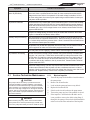
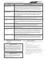
Section 6. Troubleshooting and Repair ........ 20
6.1 Service Technician Maintenance ...................... 21
Section 7. Product Specications and
Technical Data .............................. 22
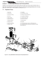
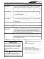
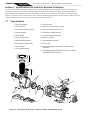
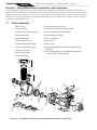
7.1 Exploded Views ................................................ 22
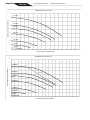
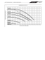
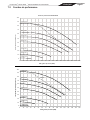
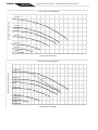
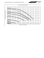
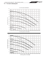
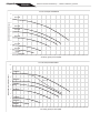
7.2 Performance Curves ........................................ 23

Page 3
ENGLISH
Jandy® Variable-Speed Pumps | Installation & Operation Manual
WARNING
RISK OF SUCTION ENTRAPMENT HAZARD, WHICH, IF NOT AVOIDED, CAN RESULT IN SERIOUS INJURY
OR DEATH. Do not block pump suction, as this can cause severe injury or death. Do not use this pump for
wading pools, shallow pools, or spas containing bottom drains, unless the pump is connected to at least two
(2) functioning suction outlets. Suction outlet (drain) assemblies and their covers must be certified to the latest
published edition of ANSI®/ASME® A112.19.8, or its successor standard, ANSI/APSP-16.
WARNING
To reduce the risk of injury, do not permit children to use this product.
WARNING
To reduce the risk of property damage or injury, do not attempt to change the backwash (multiport, slide, or full
flow) valve position with the pump running.
WARNING
Jandy pumps are powered by a high voltage electric motor and must be installed by a licensed or certified
electrician or a qualified swimming pool service technician.
WARNING
Due to the potential risk of fire, electric shock, or injuries to persons, Jandy pumps must be installed in accordance
with the National Electrical Code® (NEC®), all local electrical and safety codes, and the Occupational Safety
and Health Act (OSHA). Copies of the NEC may be ordered from the National Fire Protection Association, 1
Batterymarch Park, Quincy, MA 02169, or from your local government inspection agency.
WARNING
RISK OF ELECTRIC SHOCK, FIRE, PERSONAL INJURY, OR DEATH. (For all permanently installed units
intended for use on 15 or 20 ampere, 120 through 240 volt, single phase branch circuits). Connect only to a
branch circuit that is protected by a ground-fault circuit-interrupter protection for personnel (GFCI). Contact a
qualified electrician if you cannot verify that the circuit is protected by a GFCI. A GFCI should be provided by the
installer and should be tested on a routine basis. To test the GFCI, push the test button. The GFCI should interrupt
power. Push the reset button. Power should be restored. If the GFCI fails to operate in this manner, the GFCI
is defective. If the GFCI interrupts power to the pump without the test button being pushed, a ground current is
flowing, indicating the possibility of electrical shock. Do not use the device. Disconnect the device and have the
problem corrected by a qualified service representative before using.
WARNING
Incorrectly installed equipment may fail, causing severe injury or property damage.
Section 1. Important Safety Instructions
READ AND FOLLOW ALL INSTRUCTIONS
1.1 Safety Instructions
All electrical work must be performed by a licensed electrician and conform to all national, state, and local codes.
When installing and using this electrical equipment, basic safety precautions should always be followed, including the
following:

Page 4 ENGLISH Jandy® Variable-Speed Pumps | Installation & Operation Manual
CAUTION
This pump is for use with permanently installed pools and may also be used with hot tubs and spas, if so marked.
Do not use with storable pools. A permanently installed pool is constructed in or on the ground or in a building
such that it cannot be readily disassembled for storage. A storable pool is constructed so that it may be readily
disassembled for storage and reassembled to its original integrity.
CAUTION
Do not start pump dry! Running the pump dry for any length of time will cause severe damage and will void the
warranty.
WARNING
Chemical spills and fumes can weaken pool/spa equipment. Corrosion can cause filters and other equipment to
fail, resulting in severe injury or property damage. Do not store pool chemicals near your equipment.
CAUTION
Do not install within an outer enclosure or beneath the skirt of a hot tub. The pump requires adequate ventilation to
maintain air temperature at less than the maximum ambient temperature rating listed on the motor rating plate.
WARNING
To minimize the risk of severe injury or death, the filter and/or pump should not be subjected to the piping system
pressurization test.
Local codes may require the pool piping system to be subjected to a pressure test. These requirements are
generally not intended to apply to the pool equipment such as filters or pumps.
Zodiac® pool equipment is pressure tested at the factory.
However, if the WARNING cannot be followed and pressure testing of the piping system must include the filter
and/or pump, BE SURE TO COMPLY WITH THE FOLLOWING SAFETY INSTRUCTIONS:
• Check all clamps, bolts, lids, lock rings and system accessories to ensure they are properly installed and
secured before testing.
• RELEASE ALL AIR in the system before testing.
• Water pressure for test must NOT EXCEED 35 PSI.
• Water temperature for test must NOT EXCEED 100°F (38°C).
• Limit test to 24 hours. After test, visually check system to be sure it is ready for operation.
NOTICE: These parameters apply to Zodiac equipment only. For non-Zodiac equipment, consult equipment
manufacturer.
WARNING
• Do not connect the system to an unregulated city water system or other external source of pressurized water
producing pressures greater than 35 PSI.
• Trapped air in system can cause the filter lid to be blown off, which can result in death, serious personal injury,
or property damage. Be sure all air is out of the system before operating.
CAUTION
In order to avoid premature failure or damage to the pump motor, protect the pump from direct water exposure
from sprinklers, water runoff from rooftops and drainage, etc. Failure to comply may cause pump failure, and will
also void warranty.
SAVE THESE INSTRUCTIONS

Page 5
ENGLISH
Jandy® Variable-Speed Pumps | Installation & Operation Manual
WARNING
Pump suction is hazardous and can trap and drown or disembowel bathers. Do not use or
operate swimming pools, spas, or hot tubs if a suction outlet cover is missing, broken, or loose.
The following guidelines provide information for pump installation that minimizes risk of injury to users of
pools, spas, and hot tubs:
Entrapment Protection - The pump suction system must provide protection against the hazards of
suction entrapment.
Suction Outlet Covers - All suction outlets must have correctly installed, screw-fastened covers in
place. All suction outlet (drain) covers must be properly maintained. They must be replaced if cracked,
broken, or missing. Draincoversmustbelisted/certiedtothelatestpublishededitionofANSI®/ASME®
A112.19.8 or its successor standard, ANSI/APSP-16. The pool must be shut down and bathers must be
restricted from entering the pool until any cracked, broken, or missing drain covers are replaced.
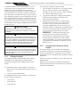
Number of Suction Outlets Per Pump - Provide at least two (2) hydraulically-balanced suction outlets,
with covers, as suction outlets for each circulating pump suction line. The centers of the suction outlets
(suction outlets) on any one (1) suction line must be at least three (3) feet apart, center to center. See
Figure 1.
The system must be built to include at least two (2) suction outlets (drains) connected to the pump
whenever the pump is running. However, if two (2) suction outlets run into a single suction line, the
singlesuctionlinemaybeequippedwithavalvethatwillshutobothsuctionoutletsfromthepump.
Thesystemshallbeconstructedsuchthatitshallnotallowforseparateorindependentshutoor
isolation of each drain. See Figure 1.
Additional pumps can be connected to a single suction line as long as the requirements above are met.
Water Velocity - The maximum water velocity through the suction outlet assembly and its cover for any
suctionoutletmustnotexceedthesuctionoutletassemblyanditscover’smaximumdesignowrate.
The suction outlet (drain) assembly and its cover must comply with the latest version of ANSI®/ASME®
A112.19.8, the standard for Suction Fittings For Use in Swimming Pools, Wading Pools, Spas,and Hot
Tubs, or its successor standard, ANSI/ASME APSP-16.
Testing and Certication - Suction outlet covers must have been tested by a nationally recognized
testing laboratory and found to comply with the latest published edition of ANSI/ASME A112.19.8 or
its successor standard, ANSI/APSP-16, the standard for Suction Fittings For Use in Swimming pools,
Wading Pools, Spas, and Hot Tubs.
Fittings-Fittingsrestrictow;forbesteciencyusefewestpossiblettings(butatleasttwo(2)suction
outlets).
Avoidttingsthatcouldcauseanairtrap.
PoolcleanersuctionttingsmustconformtoapplicableInternationalAssociationofPlumbingand
MechanicalOcials(IAPMO)standards.
1.2 Pool Pump Suction Entrapment Prevention Guidelines
SUCTION HAZARD. Can cause serious injury or death. Do not use this pump for
wading pools, shallow pools or spas containing bottom drains, unless the pump is
connected to at least two (2) functioning suction outlets.
WARNING

Page 6 ENGLISH Jandy® Variable-Speed Pumps | Installation & Operation Manual
Section 2. General Description
2.1 Introduction
Jandy® Variable Speed Pumps can be run from 600 RPM to 3450 RPM. This allows you to select the most appropriate
speed for your application. The pumps are compatible with all Jandy controllers and Zodiac® automation systems. The
pump is driven by a variable speed ECM (Electronically Commutated Motor) directly attached to the pump impeller.
The motor spins the impeller which forces water to ow through the pump. As the speed of the motor is varied, the
ow through the pump is also varied. The adjustable ow rate allows for optimization of ow during the varying
pump cycle requirements. As a result, the energy eciency of the pump is maximized resulting in cost savings to the
pool owner while also helping to save the environment.
This manual contains information for the proper installation, operation, and maintenance of Jandy variable-speed
pumps. Procedures in this manual must be followed exactly. To obtain additional copies of this manual, visit
Jandy.com.
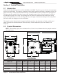
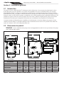
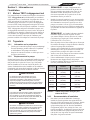
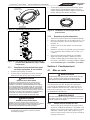
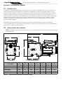
2.2 Product Dimensions
NOTE
When installing a pump, leave a minimum of two (2) feet (30 cm) of clearance above the pump for removal of
the strainer basket.
G
B
D
C
AF
E
Front Edge of Union
to Center of Bolt Holes
Bolt Holes,
Center to Center
MODEL No. A
Dimensions
B
Dimensions
C
Dimensions
D
Dimensions
E
Dimensions
F
Dimensions
G
Dimensions
VSFHP185DV2A 10" 6 1/2" 7 3/4" 12 3/4" 24 1/2" 9 1/2" 9 1/8"
VSFHP270DV2A 10" 6 1/2" 7 3/4" 12 3/4" 24 1/2" 9 1/2" 9 1/8"
VSPHP270DV2A 9 1/8" 9" 8 7/8" 14 1/8" 27 5/8" 11 5/8" 9 1/16"
VSSHP220DV2A 11 5/8" 9" 10 3/8" 15 1/4" 30 1/8" 14" 11 5/8"
VSSHP270DV2A 11 5/8" 9" 10 3/8" 15 1/4" 30 1/8" 14" 11 5/8"
Figure 1. Variable-Speed Pump Dimensions

Page 7
ENGLISH
Jandy® Variable-Speed Pumps | Installation & Operation Manual
2.3 Product Specifications
2.3.1 Specifications
Model No. THP WEF Voltage Max Watts Max Amps Union Size Weight
VSFHP185DV2A 1.85 8.5 230 VAC
115 VAC
1,700W
1,800W
8.0
16.0 2" x 2" 44 lb
[20kg]
VSFHP270DV2A 2.70 7.3
8.7
230 VAC
115 VAC
2,550W
1,840W
10.5
16.0 2" x 2" 44 lb
[20k]
VSPHP270DV2A 2.70 7.2
8.9
230 VAC
115 VAC
2,250W
1,840W
10.5
16.0 2" x 2 1/2" 64 lb
[29kg]
VSSHP220DV2A 2.20 8.5
8.8
230 VAC
115 VAC
2,190W
1,660W
10.5
16.0 2" x 2 1/2" 55 lb
[25kg]
VSSHP270DV2A 2.70 7.5
9.3
230 VAC
115 VAC
2,370W
1,675W
10.5
16.0 2" x 2 1/2" 55 lb
[25kg]
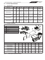
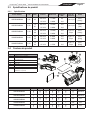
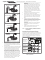
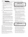
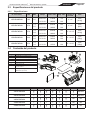
2.4 Product Contents
2
1
7
8
3
45
6
1
2
3
4
5
6
7
8
Variable Speed Pump
Installation and Operation Manual
Large Drawstring Bag
Union Nut (2)
Tailpiece (2)
O-Ring (2)
Small Adjustable Base w/Spacers
Large Adjustable Base (Optional R0546400)
ITEM DESCRIPTION
Model No. 1 2 3 4 5 6 7 8
VSFHP185DV2A • • • • • • • Optional
VSFHP270DV2A • • • • • • • Optional
VSPHP270DV2A • • • • • • NA NA
VSSHP220DV2A • • • • • • NA NA
VSSHP270DV2A • • • • • • NA NA
Figure 2. Variable-Speed Pump Carton Contents

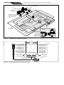
Page 8 ENGLISH Jandy® Variable-Speed Pumps | Installation & Operation Manual
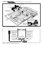
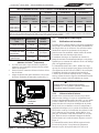
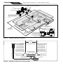
MAIN DRAINS
(Suction Outlet)
Optional
Cleaner Suction Port
MANUAL BYPASS VALVE
HEATER
FILTER
CHECK VALVE
(Check Valve recommended
for systems installed with Erosion Feeders
or Aquapure® salt chlorination systems)
PUMP
POOL/SPA
3 WAY VALVE
SPA DRAIN
(Suction Outlet)
SKIMMER
SPA RETURN
POOL
RETURN
a.
a.
MANUAL BY-PASS DETAIL:
USE WHEN FILTRATION RATE
EXCEEDS 125 GPM FOR ZODIAC
HEATERS. REFER TO THE MANUFAC-
TURER’S RECOMMENDATIONS IF
USING A DIFFERENT BRAND HEATER.
Figure 3. Typical Piping Installation
Listed/certified to the latest
published version of
ANSI/ASME A112.19.8 or
its successor standard,
ANSI/APSP-16.
Anti-entrapment
Cover/Grate or Suction
Fitting, securely-fastened
to Main Drain Sump
Listed/certified to the latest
published version of
ANSI®/ASME® A112.19.8 or
its successor standard,
ANSI/APSP-16.
Anti-entrapment
Cover/Grate or Suction
Fitting, securely fastened to
Main Drain Sump
At Least
3 Feet
Suction Outlet
(Main Drain)
Suction Outlet
(Main Drain)
Valves permitted only after tee Pump
No valves between
Tee and Main Drains
Skimmer
Figure 4. Number of Suction Outlets Per Pump

Page 9
ENGLISH
Jandy® Variable-Speed Pumps | Installation & Operation Manual
Section 3. Installation Information
3.1 Zero Clearance TEFC Motor
The Jandy pumps in this manual feature a Zero
Clearance Totally Enclosed Fan Cooled (TEFC) motor.
Unlike most TEFC motors which draw in cool air from
the back of the fan shroud and require 2"-3" of clearance,
the Jandy Zero Clearance TEFC motor pulls in air from
the top, bottom and sides of the fan shroud. The Zero
Clearance TEFC motor makes it possible to install the
pump with minimal clearance between the back of the
fan shroud and potential obstructions such as a fence or
foundation. Clearance must still be provided on the sides
of the motor and fan shroud to allow for adequate air-
ow and maintenance of the pump.
3.2 Plumbing
3.2.1 Preparation Information
1. Check the pump carton for any damage. If any
damage is found, contact the shipper or distributor
where the pump was purchased.
2. Inspect the contents of the carton and verify that all
parts are included.
3.2.2 Pump Location
Zodiac Pool Systems LLC recommends installing the
pump within one foot (30 cm) above water level. The
pump should not be elevated more than ve feet (152
cm). If the pump is located below water level, isolation
valves must be installed on both the suction and return
lines to prevent back ow of pool water during any
routine or required servicing.
WARNING
A check valve can interfere with the proper operation
of certain Suction Vacuum Release System (SVRS)
products. To avoid possible entrapment hazard, serious
injury, or death, make sure to review the operation/
owners manual of your particular SVRS product before
installing the check valve.
WARNING
To Reduce the Risk of Fire, install pool equipment in
an area where debris will not collect on or around the
equipment. Keep surrounding area clear of all debris
such as paper, leaves, pine needles and other
combustible materials.
CAUTION
In order to avoid premature failure or damage to
the pump motor, protect the pump from direct water
exposurefromsprinklers,waterrunofromrooftopsand
drainage, etc. Failure to comply may cause pump failure,
and will also void warranty.
NOTE: When the pool equipment is located
below the pool surface a leak can result in large
scale water loss or flooding. Zodiac Pool Systems
LLC cannot be responsible for such water loss or
flooding or damage caused by either occurrence.
1. Install the pump such that any disconnecting
means and/or junction boxes for power connection
are within sight of the pump and at least ve feet
horizontally from the edge of the pool and/or spa.
Choose a location that will minimize pipe turns.
NOTE In Canada, the minimum distance
maintained from the edge of the pool and/or spa as
noted above must be 3 meters (10 feet), as required
by the Canadian Electrical Code (CEC, CSA
C22.1).
2. Place the pump on a solid foundation that will
not vibrate. To further reduce the possibility of
vibration noise, bolt the pump to the foundation.
3. Assure that the foundation has adequate drainage
to prevent the pump motor from getting wet. The
pump needs to be protected from the rain and sun.
4. Make sure the pump has the proper ventilation to
prevent the motor from overheating.
5. Allow plenty of space for any maintenances by
leaving a clear area around the pump.
6. Provide adequate lighting if the equipment is in a
potentially dark area.
Pipe Size Maximum Flow Suction
(6 feet per second)
Maximum Flow
Discharge
(8 feet per second)
1½"
(38 mm)
37 GPM
(140 LPM)
50 GPM
(189 LPM)
2"
(51 mm)
62 GPM
(235 LPM)
85 GPM
(322 LPM)
2½"
(64 mm)
88 GPM
(333 LPM)
120 GPM
(454 LPM)
3"
(76 mm)
136 GPM
(515 LPM)
184 GPM
(697 LPM)
4"
(102 mm)
234 GPM
(886 LPM)
313 GPM
(1185 LPM)
Table 1. Pipe Sizing Chart for Schedule 40 PVC
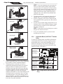
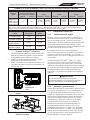
3.2.3 Installation Recommendations
1. To help prevent diculty in priming, install the
suction pipe without high points (above inlet
of pump - inverted “U”s, commonly referred to
in plumbing as an airlock) that can trap air. For
installations of equipment up to 100 feet (30 m)
from the water, refer to Table 1, the pipe sizing
chart. For installations of equipment more than 100
feet (30 m) from the water, the recommended pipe
size must be increased to the next size.

Page 10 ENGLISH Jandy® Variable-Speed Pumps | Installation & Operation Manual
NOTE To prevent entrapment, the system must be
built so it cannot operate with the pump drawing
water from only one main drain. At least two main
drains must be connected to the pump when it is in
operation. However, if two main drains run into a
single suction line, the single suction line may be
equipped with a valve that will shut off both main
drains from the pump.
4. The piping must be well supported and not forced
together where it will experience constant stress.
5. Always use properly sized valves. Jandy Diverter
Valves and Ball Valves typically have the best ow
capabilities.
6. Use the fewest possible ttings and limit the use of
90 degree elbows. Each additional tting or length
of pipe increases resistance to ow which makes
the pump work harder.
NOTE If more than ten suction fittings are needed,
the pipe size must be increased.
7. Every new installation must be pressure tested
according to local codes.
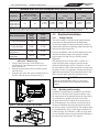
3.2.4 Adjustable Bases (VS FloProTM Models
Only)
To replace an existing pump with dierent dimensions,
use the adjustable bases to correctly align the suction
and discharge ports with existing plumbing. The VS
FloPro base and spacers increase the total height of
the pump and the height of the suction side port of the
pump. See Figure 5 and Table 2.
Pump
Height
Suction
Side
Height
No Base Required
Hayward® Super Pump®
Pentair® SuperFlo®
Sta-Rite® SuperMax®
Small Base
Hayward Super II™
Jandy PlusHP by Zodiac®
Jandy Max HP by Zodiac
Small Base + Large Base
Sta-Rite Max-E-Pro®
Sta-Rite Dura-Glas®
Sta-Rite Dura-Glas II
Sta-Rite Max-E-Glas®
Small Base with Spacers
Pentair WhisperFlo®
Sta-Rite Dyna-Glas™
Optional
(Order R0546400)
Figure 5. Base Congurations (VS FloPro Models
Only)
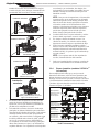
Bad Install
Air Lock
90 degree elbow
too close
4x pipe diameter
into pump
Bad Install
Good Install
Sweep Elbows in/out
for maximum efficiency
Best Install
2. The unions on both the suction and discharge ports
simplify installation and service while eliminating
the possibility of leaks at threaded adapters.
3. The pump must be connected to at least two
hydraulically-balanced main drains for each pool
pump suction line. Each drain (suction outlet)
assembly must be provided with covers and must
be listed or certied to the latest published edition
of ANSI®/ASME® A112.19.8, or its successor
standard, ANSI/APSP-16. The suction ttings of the
main drains must be at least three feet (1 m) apart
or at dierent planes. The suction ttings can be a
drain and skimmer, two drains, two skimmers, or a
skimmer with an equalizer line installed. Check the
local codes for proper installation.

Page 11
ENGLISH
Jandy® Variable-Speed Pumps | Installation & Operation Manual
Base Configuration
Suction
Side
Height
Pump
Height
1. Pump without Base 7 3/4” 12 3/4”
2. Pump with Base 8 7/8" 13 7/8”
3. Pump with Base
and Spacers
9 1/8” 14 1/8”
4. Pump with Small +
Large Base
10 3/4” 15 3/4”
Table 2. Adjustable Base Dimensions
(VS FloProTM Models Only)
1. Using a hand cutter tool, cut the plastic bars
connecting the top and bottom sets of spacers, as
shown in Figure 6.
2. Push the two top spacers and two bottom spacers
out of the base.
3. Align the pins in the four spacers with the holes in
the base. Snap the spacers into place (Fig. 7).
X
X
Cut
spacers
at X.
Figure 6. Cut Sets of Spacers Out of Base
Figure 7. Snap Spacers into Place
MINIMUM WIRE SIZE AND MINIMUM OVERCURRENT PROTECTION*
Distance from Sub-Panel 0-50 feet (15 meters) 50-100 feet (15-30 meters) 100-200 feet (30-60 meters)
Pump Model
Inverse - Time Circuit Breaker or
Branch Fuse AMPs
Class: CC, G, H, J, K, RK, or T Voltage Voltage Voltage
230 VAC 115 VAC 230 VAC 115 VAC 230 VAC 115 VAC 230 VAC 115 VAC
VSFHP185DV2A
VSFHP270DV2A
VSPHP270DV2A
VSSHP220DV2A
VSSHP270DV2A
15A 20A 14 AWG
(2.1mm2)
12 AWG
(3.3mm2)
12 AWG
(3.3mm2)
10 AWG
(5.3mm2)
10 AWG
(5.3mm2)
10 AWG
(5.3mm2)
*Assumes three (3) copper conductors in a buried conduit and 3% maximum voltage loss in branch circuit. All National Electrical Code® (NEC®) and
local codes must be followed. Table shows minimum wire size and branch fuse recommendations for a typical installation per NEC.
3.3 Electrical Installation
3.3.1 Voltage Checks
The correct voltage, as specied on the pump data plate,
is necessary for proper performance and long motor
life. Incorrect voltage will decrease the pump’s ability to
perform and could cause overheating, reduce the motor life,
and result in higher electric bills.
It is the responsibility of the electrical installer to provide
data plate operating voltage to the pump by ensuring
proper circuit sizes and wire sizes for this specic
application.
The National Electrical Code® (NEC®, NFPA-70®)
requires all pool pump circuits be protected with a
Ground Fault Interrupter (GFCI). Therefore, it is also
the responsibility of the electrical installer to ensure that
the pump circuit is in compliance with this and all other
applicable requirements of the National Electrical Code
(NEC) and any other applicable installation codes.
CAUTION
Failure to provide data plate voltage (+/- 10%) during
operation will cause the motor to overheat and void the
warranty.
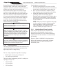
3.3.2 Bonding and Grounding
In addition to being properly grounded as described in
the Electrical Wiring section, and in accordance with
the requirements of the National Electrical Code (NEC),
or in Canada the Canadian Electrical Code (CEC),
the pump motor must be bonded to all metal parts of
the swimming pool, spa or hot tub structure and to all
electrical components and equipment associated with
the pool/spa water circulation system.The bonding must
be accomplished by using a solid copper conductor, No.
8 AWG or larger. In Canada No. 6 AWG or larger must
be used. Bond the motor using the external bonding lug
provided on the motor frame. See Figure 8.

Page 12 ENGLISH Jandy® Variable-Speed Pumps | Installation & Operation Manual
National Electrical Code® (NEC®) requires bonding
of the Pool Water. Where none of the bonded pool
equipment, structures, or parts are in direct connection
with the pool water; the pool water shall be in
direct contact with an approved corrosion-resistant
conductive surface that exposes not less than 5800
mm² (9 in²) of the surface area to the pool water at all
times. The conductive surface shall be located where
it is not exposed to physical damage or dislodgement
during usual pool activities, and it shall be bonded in
accordance with the bonding requirements of NEC
Article 680. Refer to locally enforced codes for any
additional bonding requirements.
WARNING
Always disconnect the power source before working on a
motor or its connected load.
WARNING
Make sure that the control switch, time clock, or control
system is installed in an accessible location, so that in the
event of an equipment failure or a loose plumbing fitting,
the equipment can be turned off. This location must not
be in the same area as the pool pump, filter, and other
equipment.
CAUTION
The pump must be permanently connected to a dedicated
electrical circuit. No other equipment, lights, appliances, or
outlets may be connected to the pump circuit.
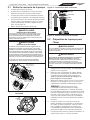
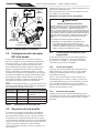
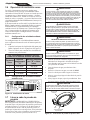
3.3.3 Electrical Wiring
The Jandy pump models covered in this installation and
operation manual provide separate compartments for
high voltage and low voltage wiring.
The low voltage compartment provides 2 openings:
• RS-485 quick connect port (see Figure 8)
• 3/8" conduit port (threaded)
The high voltage compartment provides 3 conduit port
openings (see Figure 9):
• 1/2" (threaded)
• 1/2" (threadless)
• 3/4" (threadless)
Conduit ttings are not provided.
1. Secure the pump using the green screw provided.
Ground before attempting to connect to an electrical
power supply. Do not ground to a gas supply line.
2. Wire size must be adequate to minimize voltage
drop during the start-up and operation of the pump.
3. Insulate all connections carefully to prevent
grounding or short-circuits. Sharp edges on
terminals require extra protection. For safety, and to
prevent entry of contaminants, reinstall all conduit
and terminal box covers. Do not force connections
into the conduit box.
NOTE: When power alone is supplied to this pump,
it will not operate. It requires a digital command
sent to it by either a variable speed controller
(JEP-R, iQPUMP01), an automation system, or use
of the dry contacts (See figure 10 and 11).
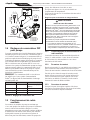
3.3.4 Variable-Speed Pump Controller
Jandy Variable-Speed pumps are compatible with
all controllers and Automation Systems made by
Zodiac Pool Systems LLC. The variable-speed pump
communicates with the controllers via a four-wire RS-
485 interface.
Please see Figure 8 for RS-485 wiring instructions.
Refer to the automation system manual for further
instructions on how to connect the pump to an
automation system.

Page 13
ENGLISH
Jandy® Variable-Speed Pumps | Installation & Operation Manual
Remove screw and
RS485 quick
connect port cover
Feed RS485 connec-
tor and cable through
the RS485 quick
connect port and
strain relief channel.
Connect the RS485
and secure the
RS485 quick connect
port cover back into
place with the screw.
2
3
Wire the cable to the RS485 connector
in order of Red(1), Black(2), Yellow (3),
Green (4)
1
4
3-YELLOW
2-BLACK
4-GREEN
1-RED
RS485 Cable (22 AWG)
Figure 8. RS-485 Quick Connect Port with Wiring

Page 14 ENGLISH Jandy® Variable-Speed Pumps | Installation & Operation Manual
An access cover with Phillips-head screw must be
removed before proceeding.
Auxiliary Load Connection Requirements
WARNING
ELECTRICAL SHOCK HAZARD
Due to the potential risk of fire, electric shock, or injuries
to persons, Jandy® Pumps and any auxiliary loads must
be installed in accordance with the National Electrical
Code® (NEC®), all local electrical and safety codes, and
the Occupational Safety and Health Act (OSHA). Copies
of the NEC may be ordered from the National Protection
Association, 1 Batterymarch Park, Quincy, MA 02169, or
from your local government inspection agency.
In Canada, Jandy Pumps must be installed in accordance
with the Canadian Electrical Code (CEC).
• The Auxiliary Load relay contacts are rated at
230V/115V, 11A RMS. Please ensure the requirements
of the equipment to be connected to the Auxiliary Load
do not exceed this rating.
3.5.1 Auxiliary Relay Operation
Characteristics
Auxiliary Relay contact activation is speed dependent.
Auxiliary Relay 1 has an activation speed of 1725 RPM
and Auxiliary Relay 2 has an activation speed of 2250
RPM.
3.5.2 Contact Closure
From a stopped condition, there is a three-minute delay
before the Auxiliary Relay contact is closed when the
motor speed reaches and maintains the activation speed.
Once the three minute run time criteria has been reached,
when going from an RPM below the activation speed to
an RPM above the activation speed, there is a 5-second
delay before the Auxiliary Relay contact is closed.
3.5.3 Contact Opening
When going from an RPM above the activation speed to
an RPM below the activation speed, the relay opening is
always immediate.
BLACK
YELLOW
RED
GREEN
RS485 4321
RED
BLACK
YELLOW
GREEN
REMOTE CONTROL
54321
INPUT 2
INPUT 3
INPUT 4
COMMON
INPUT 1
2-Position
DIP Switch 1- 3/8” Threaded
2- 3/4” Threadless
3- 1/2” Threadless
4- 1/2” Threaded
Bonding Lug
Controller
(Rear View)
RS485
Cable (22 AWG)
1
2
34
4321
BLACK
YELLOW
RED
GREEN
Figure 9. Wiring to a Controller
3.4 Pump DIP Switch Settings
The motor is equipped with an auto sensing power
circuit which eliminates the need for DIP switches
1 and 2. As shown in Figures 9, the 2-position DIP
switch serves the function of pump addressing when
using multiple pumps. If the pump is connected to a
JEP-R controller or iQPUMP01, DIP switches 3 and 4
must remain in the OFF position. If connecting to an
automation system that supports multiple pumps, use
the DIP switches (See Table 3) to set the address for the
pump and refer to the automation system's manual for
additional instructions.
NOTE DIP switches 3 and 4 must only be used if your
Zodiac® Automation system does NOT have RS-485
auto-addressing capabilities.
Switch 3 Switch 4 Pump Address
OFF OFF PUMP 1 (Factory Default)
ON OFF PUMP 2
OFF ON PUMP 3
ON ON PUMP 4
Table 3. DIP Switch Settings
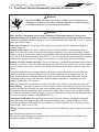
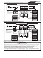
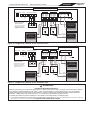
3.5 Auxiliary Relay Operation
Jandy pump model numbers ending with "2A" are
equipped with a terminal bar that provides user access to
two built-in Auxiliary Relays. The normally-open relays
are activated under certain operating conditions and
are intended to be used to control external devices that
require system water ow for proper functioning, such
as booster pumps, salt water chlorinators, etc.
See Figures 10 and 11 for compartment’s location
details.

Page 15
ENGLISH
Jandy® Variable-Speed Pumps | Installation & Operation Manual
Breaker Panel
Filter Pump Junction Box
Auxillary 1
RS485
Line (in)
Red
Black
Yellow
Green
Load (out)
1 2
Line (in)
Line 1
Load 1
Load 2 Load (out)
1 2
Auxillary 2
Line (in)
Load (out)
1 2
Line (in)
Load (out)
1 2
Auxillary Load
230VAC
External Enclosure
230/115VAC
Supply Power
(GFCI Breaker)
Breaker Panel
230VAC Supply Power
(GFCI Breaker)
Breaker Panel
230VAC Supply Power
(GFCI Breaker)
1 2 3 4
Dry Contacts
1 2 3 4 COM L1 L2/N
Supply Power Input
Ground
Ground
Load 1
Load 2
Auxillary Load
230VAC
Ground
Dry Contact Speed Settings
Please refer to table 4 on the
following page for Dry Contact
Speed Settings.
DIP Switch
3 4
OFF OFF
Line 2/Neutral
Line 1
Line 1
Line 2
Line 2
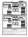
Figure 10. 230V Auxiliary Relay Wiring Diagram*
Breaker Panel
Filter Pump Junction Box
Auxillary 1
RS485
Line (in)
Red
Black
Yellow
Green
Load (out)
1 2
Line (in)
Line 1
Load 1
Load 2 Load (out)
1 2
Auxillary 2
Line (in)
Load (out)
1 2
Line (in)
Load (out)
1 2
Auxillary Load
115VAC
External Enclosure
230/115VAC
Supply Power
(GFCI Breaker)
Breaker Panel
115VAC Supply Power
(GFCI Breaker)
Breaker Panel
115VAC Supply Power
(GFCI Breaker)
1 2 3 4
Dry Contacts
1 2 3 4 COM L1 L2/N
Supply Power Input
Ground
Ground
Load 1
Load 2
Auxillary Load
115VAC
Ground
Dry Contact Speed Settings
Please refer to table 4 on the
following page for Dry Contact
Speed Settings.
DIP Switch
3 4
OFF OFF
Line 1
Line 1
Neutral
Neutral
Line 2/Neutral
Figure 11. 115V Auxiliary Relay Wiring Diagram*
* WARNING
ELECTRICAL SHOCK HAZARD
Due to the potential risk of fire, electric shock, or injuries to persons, Jandy® Pumps and any auxiliary loads must be installed
in accordance with the National Electrical Code® (NEC®), all local electrical and safety codes, and the Occupational Safety and
Health Act (OSHA). Copies of the NEC may be ordered from the National Protection Association, 1 Batterymarch Park, Quincy,
MA 02169, or from your local government inspection agency.
In Canada, Jandy Pumps must be installed in accordance with the Canadian Electrical Code (CEC).
• The Auxiliary Load relay contacts are rated at 230V/115V, 11A RMS. Please ensure the requirements of the equipment to be
connected to the Auxiliary Load do not exceed this rating.

Page 16 ENGLISH Jandy® Variable-Speed Pumps | Installation & Operation Manual
3.6 Dry Contact Operation
External relays or switches can be used with the dry
contacts if a Zodiac controller is not connected to the
RS-485 line. By creating a circuit that runs between the
dry contact, the external switch/relay, and the common
on the dry contact, when the circuit is closed the pump
will turn on, prime, and go to a pre-determined speed
indenitely until the short is broken.
If no inputs are jumped to common, the RPM is zero.
When any Zodiac controller is connected through RS-
485, all dry contact commands will be ignored. Refer to
Figures 10 and 11 for dry contact wiring. Refer to table 4
for dry contact speed settings.
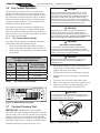
3.6.1 Dry Contact Speed Settings
Dry contact speeds settings were adjusted with motor
serial numbers beginning with the letter B.
1. Please refer to the motor rating label to nd the
motor serial number. Example is shown in Fig. 12.
2. Refer to table 4 to determine the dry contact speeds
for the motor.
Dry Contact Speeds Are Based
On Motor Serial Numbers
Dry
Contact
Serial #
Begins with
"A"
Serial # Begins
with "B" or Later
1 3000 RPM 3450 RPM
2 1400 RPM 1375 RPM
3 2200 RPM 2600 RPM
4 1725 RPM 1750 RPM
Table 4. Dry Contact Speed Settings
(G) GROUND
EARTH
(L2/N)
(L1)
USE COPPER
CONDUCTORS
ONLY
ACCEPTABLE
FOR FIELD
WIRING
LINE 2
NEUTRAL
LINE 1
ENCL: TEFC
ROT: CWLE
FR: 56
Electronically Protected
INSUL: CLASS F IPX5
AMB: 50 C
DUTY: CONT
ZODIAC POOL SYSTEMS LLC, www.zodiac.com
MOTOR SERIAL NO:
50 HZ 60 HZ
1 PHASE 1 PHASE
230 VAC 230 / 115 VAC
1.85 THP 1.85 THP MAX
8 A 8 / 16 A
P1: 1.70 kW
P2: 1.38 kW
RPM: 600 - 3450
SF: 1.00
SF: 1.00
H0662700 Rev G
5009595
Conforms to ANSI/UL
STD 1004-1, 1004-7,
Cer�fied to CSA STD
C22.2 No. 100 & 77
UL 1081, CSA C22.2 108 – Pool Pump Duty
B0245802
H0662700 REV G
Figure 12. Motor Rating Plate Label
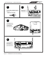
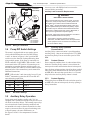
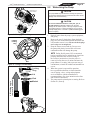
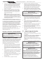
3.7 Conduct Pressure Test
IMPORTANT: VSSHP220DV2A and VSSHP-
270DV2A come with an additional disposable o-ring for
pressure testing. This is the blue pressure test o-ring (See
Figures 13 and 14). If you opened the pump lid before
conducting the pressure test, the blue o-ring may fall out.
If the blue o-ring falls out, it must be re-installed on the
lid before beginning the pressure test (See 3.6.2).
WARNING
When pressure testing a system with water, air is often
trapped in the system during the filling process. This air
will compress when the system is pressurized. Should the
system fail, this trapped air can propel debris at a high
speed and cause injury. Every effort to remove trapped air
must be taken, including opening the valve on the filter and
loosening the pump basket lid while filling the pump.
WARNING
Trapped air in the system can cause the filter lid to be
blown off, which can result in death, serious injury, or
property damage. Be sure all air is properly purged out of
the system before operating. DO NOT USE COMPRESSED
AIR TO PRESSURE TEST OR CHECK FOR LEAKS.
WARNING
ELECTRICAL SHOCK HAZARD
Do not pressure test above 35 PSI. Pressure testing
must be done by a trained pool professional. Circulation
equipment that is not tested properly might fail, which could
result in severe injury or property damage.
WARNING
When pressure testing the system with water, it is very
important to make sure that the pump basket lid is
completely secure.
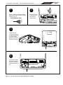
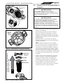
1. Before pressurizing the system, ensure the lock
ring "locked" indicators align with the suction and
pressure side ports on the pump.
2. Fill the system with water to eliminate trapped air.
3. Pressurize the system with water to no more than
35 PSI.
4. Close the valve to seal the water in the system.
5. Observe the system for any leaks or pressure decay.
6. If there are lid leaks, repeat this procedure. For
Zodiac Technical Support, call 800.822.7933
CAUTION
Do not open the pump lid before pressure testing as the
blue pressure test o-ring may fall out. If this happens, you
will need to place it back on the lid.
FMA58D
Blue Pressure Test O-ring
Seal
Lid with
Locking
Ring
Figure 13. Blue Pressure Test O-ring

Page 17
ENGLISH
Jandy® Variable-Speed Pumps | Installation & Operation Manual
Lid with
Locking
Ring
and
Seal
Blue
Pressure
Test
O-ring
Pump
Debris
Trap
Basket
(Inside
Pump)
(Note: Discard
after pressure
test is complete.)
Figure 14. Exploded View with Blue Pressure Test
O-ring (VSSHP Pump Models Only)
3.7.1 Replace Blue O-ring Before Pressure
Testing, if necessary
1. Make sure that the pump is turned o.
2. Make sure that the switch to the circuit breaker that
powers the pump motor is turned o.
WARNING
ELECTRICAL SHOCK HAZARD
Due to the potential risk of fire, electric shock, or injuries to
persons, Jandy® Pumps must be installed in accordance
with the National Electrical Code® (NEC®), all local electrical
and safety codes, and the Occupational Safety and
Health Act (OSHA). Copies of the NEC may be ordered
from the National Protection Association, 1 Batterymarch
Park, Quincy, MA, 02169, or from your local government
inspection agency.
In Canada, Jandy Pumps must be installed in accordance
with the Canadian Electrical Code (CEC).
WARNING
ELECTRICAL SHOCK HAZARD
Turn off the pump and the main breaker in the pump
electrical circuit before starting the procedure. Failure to
comply may cause a shock hazard, resulting in severe
personal injury or death.
3. Make sure all necessary isolation valves are closed
to prevent pool water from reaching the pump.
4. Following the markings on the locking ring, turn
the ring counter-clockwise until the ‘START’
markings align with the ports.
5. Carefully remove the lid with locking ring.
Upside Down View of
Bottom of Lid
Step where
O-ring is Seated
Groove where
Seal is Seated
Figure 15. Placement of Blue Pressure Test O-ring
3.7.2 Replace Blue O-ring
1. Turn the lid with locking ring upside down.
2. Place the blue o-ring on the step located ¼" from
the bottom of the lid. See Figure 15.
3. Make sure that the o-ring is properly seated.
4. Install the lid, making sure that the blue o-ring sits
in the housing without “binding” or “rolling” o.
5. Follow the markings on the locking ring, align
‘START’ markings with the ports and turn
clockwise until ‘LOCKED’ markings align. Do not
tighten past the ‘LOCKED’ marking.
Section 4. Operation
4.1 Start-up
CAUTION
Never run the pump without water. Running the pump “dry”
for any length of time can cause severe damage to both the
pump and motor and will void the warranty.
If this is a new pool installation, make sure all piping
is clear of construction debris and has been properly
pressure tested. The lter should be checked for
proper installation, verifying that all connections and
clamps are secure according to the manufacturer’s
recommendations.
WARNING
To avoid risk of property damage, personal injury or death,
verify that all power is turned off before starting these steps.
4.1.1 Pump Below Water Level
1. Ensure the pump lid is secure by verifying the
“locked” indicators are aligned with the pump’s
ports. Hand tighten only, do not use tools. Make
sure valves are open and the pump unions are tight.
2. Open any isolation valves that may be in place
between the pump and the pool’s main drain(s) and
skimmer(s).
3. Open the air relief valve on the lter. This will
allow air to begin to escape the system and ll the
pump with water for priming.
4. Restore power to the pump and start the pump.
5. When water starts to come out of the air relief valve
on the lter, close the air relief valve.
6. Inspect system for any leaks.
4.1.2 Pump Above Water Level
1. Open the air relief valve on the lter.
2. Remove the pump lid and ll the basket with water.
3. Prior to replacing the lid, check for debris around
the lid o-ring seat. Debris around the lid o-ring seat
may cause an air leak and will make it dicult for
the pump to prime.

Page 18 ENGLISH Jandy® Variable-Speed Pumps | Installation & Operation Manual
4. Tighten the lid by verifying the “locked” indicators
on the lid are aligned with the pump’s ports. Hand
tighten only, do not use tools. Make sure all valves
are open and the pump unions are tight.
5. Restore power to the pump and start the pump.
6. Once the pump has primed and water comes out of
the air relief valve on the lter, close the air relief
valve and inspect the system for any leaks.
NOTE All pumps in this manual are NSF-certified
as being able to prime at heights up to 10 ft above
the pool water level, at sea level. However, to
achieve better self-priming, install the pump as
close as possible to the water level of the pool.
See Installation Recommendations in Section 3.2.3 for
proper elevation and pipe size.
The default priming speed is 2750 RPM. The pump will
take approximately 15 minutes to prime at this priming
speed when the pump is located 10 feet above the pool
water. If priming speed is adjusted to 3450 RPM, the
pump should prime within 6 minutes at 10 feet above the
water level.
If the pump does not prime and all the instructions to this
point have been followed, check for a suction leak. If
there is no leak, repeat Steps 1 through 5.
For technical assistance, call Zodiac Technical Support
at 800.822.7933.
Section 5. Service & Maintenance
CAUTION
To avoid damage to the plastics, do not use lubricant or
sealant on the o-ring. Only soapy water should be used to
install and lubricate the o-ring.
Clean Pump Basket
Debris that accumulates in the pump lter basket
will begin to block the ow of water. For optimal
pump performance, the pump lter basket needs to be
inspected and cleaned on a weekly basis. Depending on
the location and environment of the pool, more frequent
inspection may be required.
1. Inspect the pump lter basket for debris by looking
through the clear pump lid. This can be done
with or without the pump running. If debris has
accumulated, proceed to step 2.
2. Turn o the power to the pump. If the pump is
located below the water level, close the isolation
valves on the suction and discharge sides of the
pump to prevent backow of water.
3. Turn the locking ring counter-clockwise until
'START' aligns with the ports. Remove the lid.
4. Lift the basket out of the pump.
5. Dispose of the debris and thoroughly clean the
basket, making sure all the holes are open. Using
a garden hose, spray the basket from the outside to
help clear the holes. Remove any remaining debris.
6. Replace the basket in the pump by aligning the
opening with the suction pipe. If aligned properly,
the basket will drop easily into place. Do not force
it into place.
CAUTION
A misaligned basket will cause the lid to be improperly
seated, allowing an air leak, which could result in pump
damage.
7. Remove the lid seal and remove debris around the
lid seal seat, as this can allow air to leak into the
system. Clean the lid seal and place it on the lid.
8. Replace the lid with locking ring. Hand-tighten the
lid to make an air-tight seal. Do not use any tools to
tighten the lid: hand-tighten only.
9. Verify that all valves have been returned to the
proper position for normal operation.
10. Open the pressure release valve on the lter, and
make sure it is clean and ready for operation.
11. Turn on the power to the pump. Once all the air has
been evacuated from the lter, close the pressure
release valve.
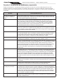
5.1 Removing the Pump Lid
1. Make sure that the pump is turned OFF.
2. Make sure that the switch to the circuit breaker to
the motor is turned OFF.
3. Make sure all necessary isolation valves are closed
to prevent water from reaching the pump.
4. Following the markings on the locking ring, turn
the ring counter-clockwise until the ‘START’
markings align with the ports. See Figures 16.
5. Carefully remove the lid with locking ring.
WARNING
ELECTRICAL SHOCK HAZARD
Turn off all switches and the main breaker in the variable-
speed pump electrical circuit before starting the procedure.
Failure to comply may cause a shock hazard resulting in
severe personal injury or death.
WARNING
ELECTRICAL SHOCK HAZARD
Due to the potential risk of fire, electric shock, or injuries to
persons, Jandy® Pumps must be installed in accordance
with the National Electrical Code® (NEC®), all local electrical
and safety codes, and the Occupational Safety and
Health Act (OSHA). Copies of the NEC may be ordered
from the National Protection Association, 1 Batterymarch
Park, Quincy, MA, 02169, or from your local government
inspection agency.
In Canada, Jandy Pumps must be installed in accordance
with the Canadian Electrical Code (CEC).

Page 19
ENGLISH
Jandy® Variable-Speed Pumps | Installation & Operation Manual
Rotate locking ring
counter clockwise
Align START
with port
Figure 16. Disengage Lock Ring
Lid with
Locking
Ring
Seal
Figure 17. O-ring in Lid Assembly
Basket
Seal
Lid
Locking
Ring
Lift locking ring to
remove lid with seal
Figure 18. Remove Pump Lid
5.2 Winterizing the Pump
CAUTION
The pump must be protected when freezing temperatures
are expected. Allowing the pump to freeze will cause severe
damage and void the warranty.
CAUTION
Do not use antifreeze solutions in the pool, spa, or
hot tub systems. Antifreeze is highly toxic and may
damage the circulation system. The only exception to this
is Propylene Glycol. For more information, see your local
pool/spa supply store or contact a qualified swimming pool
service company.
1. Drain all water from the pump, system equipment,
and piping.
2. Remove the two (2) drain plugs. Store the drain
plugs in a safe location and reinstall them when the
cold weather season is over. Ensure the drain plugs
and o-rings are not misplaced.
3. Keep the motor covered and dry. Do not cover
the pump with plastic, because this will create
condensation that will damage the pump.
NOTE Zodiac Pool Systems LLC recommends
having a qualified service technician or electrician
properly disconnect the electrical wiring at
the switch or junction box. Once the power is
removed, loosen the two (2) unions and store the
pump indoors. For safety, and to prevent entry of
contaminants, reinstall all conduit and terminal box
covers.
4. When the system is reopened for operation,
have a qualied technician or electrician make
sure all piping, valves, wiring and equipment
are in accordance with the manufacturer’s
recommendations. Pay close attention to the lter
and electrical connections.
5. The pump must be primed prior to starting. Refer to
Section 4.1, Start-up.

Page 20 ENGLISH Jandy® Variable-Speed Pumps | Installation & Operation Manual
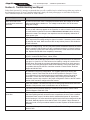
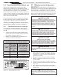
Section 6. Troubleshooting and Repair
Zodiac Pool Systems LLC strongly recommends that you call a qualied service technician to perform any repairs on
the lter/pump system. To locate a qualied technician, check your local yellow pages or visit ZodiacPoolSystems.
com or ZodiacPoolSystems.ca and click on “Find a Dealer.”
Symptom Possible Cause/Solution
Motor won't start or the
controller does not detect
the motor
No power to the motor. Have a certified professional check the voltage on the main
power terminal with the breaker on. The voltage must be within 10% of the motor
rating plate voltage.
The motor experienced an error. Power cycle the motor. If the motor has experienced
an error, a fault code may appear on the controller. In order to clear the error, turn off
the main breaker connected to the motor. Wait at least 5 minutes before returning
power to the motor. The voltage in the capacitors must be completely drained for a
proper power cycle.
Improper low voltage wiring. The RS-485 connection must be secure with no broken
wires. Inspect the low voltage wiring for signs of corrosion. If necessary cut the wires
off and strip new leads. Make sure there are not any broken pieces of wire inside the
RS-485 connector.
Broken low voltage wiring. The wire may have breaks somewhere between the motor
and the controller. With all power off, take a multimeter and set it to Ohms/Continuity.
Check continuity of each of the low voltage lines from the motor side to the controller
side. Replace the RS-485 wires completely if necessary.
Improper low voltage wiring. Check the wiring of the RS-485 connector. Wire colors
for pins 1-4 should be Red, Black, Yellow, Green.
Test the drive with the RS-485 jumper method. Using small sections of 22 AWG wire,
jump pins 1 to 3 and 2 to 4. These wires can be made by cutting off a section of the
RS-485 wires. Re-install the connector and attach the access cover. Apply power to
the motor. The motor should spin at 2600 RPM indefintely. If the motor works, there
is a problem with the RS-485 line or with the controller. Contact Zodiac Technical
Support at 800.822.7933
DIP switches in the wrong configuration. The variable speed drive has two DIP
switches;3and4.ThesemustbothbeintheOFFpositionforPump01.Thisis
the configuration for all controllers that are not automation and the first pump for
automation. If more than one variable speed pump is being controlled with an
automation system, they must be in the proper configuration. Refer to the DIP switch
section of the manual to configure the other motors.
Check the schedule. The motor will only turn on during programmed times set in the
controller. Verify that the motor is scheduled to turn on at that time.
If the motor still has problems starting or continues to show faults, contact Zodiac
Technical Support at 800.822.7933
Motor starts but shuts off
soon after
Debris may be stuck between the impeller and the diffuser. This will prevent the drive
shaft from spinning and will cause the motor to experience an error. Have a certified
professional check to see if the drive shaft is seized with all power off. A quick test
can be inserting a 5/16" allen wrench through the back of the fan housing and into the
drive shaft. Manually spin the drive shaft to check if it is seized. If large amounts of
debris are found, check your strainer basket for breaks. Replace the strainer basket if
necessary.
If the motor still has problems starting, contact Zodiac Technical Support at
800.822.7933
La page charge ...
La page charge ...
La page charge ...
La page charge ...
La page charge ...
La page charge ...
La page charge ...
La page charge ...
La page charge ...
La page charge ...
La page charge ...
La page charge ...
La page charge ...
La page charge ...
La page charge ...
La page charge ...
La page charge ...
La page charge ...
La page charge ...
La page charge ...
La page charge ...
La page charge ...
La page charge ...
La page charge ...
La page charge ...
La page charge ...
La page charge ...
La page charge ...
La page charge ...
La page charge ...
La page charge ...
La page charge ...
La page charge ...
La page charge ...
La page charge ...
La page charge ...
La page charge ...
La page charge ...
La page charge ...
La page charge ...
La page charge ...
La page charge ...
La page charge ...
La page charge ...
La page charge ...
La page charge ...
La page charge ...
La page charge ...
La page charge ...
La page charge ...
La page charge ...
La page charge ...
La page charge ...
La page charge ...
La page charge ...
La page charge ...
La page charge ...
La page charge ...
La page charge ...
La page charge ...
La page charge ...
La page charge ...
La page charge ...
La page charge ...
-
 1
1
-
 2
2
-
 3
3
-
 4
4
-
 5
5
-
 6
6
-
 7
7
-
 8
8
-
 9
9
-
 10
10
-
 11
11
-
 12
12
-
 13
13
-
 14
14
-
 15
15
-
 16
16
-
 17
17
-
 18
18
-
 19
19
-
 20
20
-
 21
21
-
 22
22
-
 23
23
-
 24
24
-
 25
25
-
 26
26
-
 27
27
-
 28
28
-
 29
29
-
 30
30
-
 31
31
-
 32
32
-
 33
33
-
 34
34
-
 35
35
-
 36
36
-
 37
37
-
 38
38
-
 39
39
-
 40
40
-
 41
41
-
 42
42
-
 43
43
-
 44
44
-
 45
45
-
 46
46
-
 47
47
-
 48
48
-
 49
49
-
 50
50
-
 51
51
-
 52
52
-
 53
53
-
 54
54
-
 55
55
-
 56
56
-
 57
57
-
 58
58
-
 59
59
-
 60
60
-
 61
61
-
 62
62
-
 63
63
-
 64
64
-
 65
65
-
 66
66
-
 67
67
-
 68
68
-
 69
69
-
 70
70
-
 71
71
-
 72
72
-
 73
73
-
 74
74
-
 75
75
-
 76
76
-
 77
77
-
 78
78
-
 79
79
-
 80
80
-
 81
81
-
 82
82
-
 83
83
-
 84
84


