Tannoy VLS 15 (EN 54) Guide de démarrage rapide
- Catégorie
- Équipement musical supplémentaire
- Taper
- Guide de démarrage rapide
Ce manuel convient également à

Quick Start Guide
VLS SERIES
VLS 30
Passive Column Array Loudspeaker with 30 Drivers and FAST Dispersion
Control for Installation Applications
VLS 15 (EN 54)
Passive Column Array Loudspeaker with 15 Drivers and FAST Dispersion
Control for Installation Applications (EN 54-24 Certied)
VLS 7 (EN 54)
Passive Column Array Loudspeaker with 7 Full Range Drivers and FAST Dispersion
Control for Installation Applications (EN 54-24 Certied)
V 1.0

2 VLS Series Speakers Quick Start Guide 3
Las terminales marcadas con este símbolo
transportan corriente eléctrica de
magnitud suciente como para constituir
un riesgo de descarga eléctrica. Utilice solo cables de
altavoz profesionales y de alta calidad con conectores
TS de 6,3 mm o de bayoneta prejados. Cualquier otra
instalación o modicación debe ser realizada únicamente
por un técnico cualicado.
Este símbolo, siempre que aparece,
leadvierte de la presencia de voltaje
peligroso sin aislar dentro de la caja;
estevoltaje puede ser suciente para constituir un riesgo
dedescarga.
Este símbolo, siempre que aparece,
leadvierte sobre instrucciones operativas
y de mantenimiento que aparecen en la
documentación adjunta. Por favor, lea el manual.
Atención
Para reducir el riesgo de descarga
eléctrica, no quite la tapa (o la parte
posterior). No hay piezas en el interior del equipo que
puedan ser reparadas por el usuario. Si es necesario,
póngase en contacto con personal cualicado.
Atención
Para reducir el riesgo de incendio o
descarga eléctrica, no exponga este
aparato a la lluvia, humedad o alguna otra fuente que
pueda salpicar o derramar algún líquido sobre el aparato.
Nocoloque ningún tipo de recipiente para líquidos sobre
el aparato.
Atención
Las instrucciones de servicio deben
llevarlas a cabo exclusivamente personal
cualicado. Para evitar el riesgo de una descarga eléctrica,
no realice reparaciones que no se encuentren descritas
en el manual de operaciones. Lasreparaciones deben ser
realizadas exclusivamente por personalcualicado.
1. Lea las instrucciones.
2. Conserve estas instrucciones.
3. Preste atención a todas las advertencias.
4. Siga todas las instrucciones.
5. No use este aparato cerca del agua.
6. Limpie este aparato con un paño seco.
7. No bloquee las aberturas de ventilación. Instale el
equipo de acuerdo con las instrucciones del fabricante.
8. No instale este equipo cerca de fuentes de calor
tales como radiadores, acumuladores de calor, estufas u
otros aparatos (incluyendo amplicadores) que puedan
producir calor.
9. No elimine o deshabilite nunca la conexión a tierra
del aparato o del cable de alimentación de corriente.
Unenchufe polarizado tiene dos polos, uno de los cuales
tiene un contacto más ancho que el otro. Una clavija con
puesta a tierra dispone de tres contactos: dos polos y la
puesta a tierra. El contacto ancho y el tercer contacto,
respectivamente, son los que garantizan una mayor
seguridad. Si el enchufe suministrado con el equipo no
concuerda con la toma de corriente, consulte con un
electricista para cambiar la toma de corriente obsoleta.
10. Coloque el cable de suministro de energía de manera
que no pueda ser pisado y que esté protegido de objetos
alados. Asegúrese de que el cable de suministro de
energía esté protegido, especialmente en la zona de la
clavija y en el punto donde sale del aparato.
11. Use únicamente los dispositivos o accesorios
especicados por el fabricante.
12. Use únicamente la
carretilla, plataforma,
trípode, soporte o mesa
especicados por el
fabricante o suministrados
junto con el equipo.
Altransportar el equipo,
tenga cuidado para evitar
daños y caídas al tropezar con algún obstáculo.
13. Desenchufe el equipo durante tormentas o si no va a
utilizarlo durante un periodo largo.
14. Confíe las reparaciones únicamente a servicios
técnicos cualicados. La unidad requiere mantenimiento
siempre que haya sufrido algún daño, si el cable de
suministro de energía o el enchufe presentaran daños,
sehubiera derramado un líquido o hubieran caído objetos
dentro del equipo, si el aparato hubiera estado expuesto
a la humedad o la lluvia, si ha dejado de funcionar de
manera normal o si ha sufrido algún golpe o caída.
15. Al conectar la unidad a la toma de corriente eléctrica
asegúrese de que la conexión disponga de una unión
atierra.
16. Si el enchufe o conector de red sirve como único
medio de desconexión, éste debe ser accesiblefácilmente.
17. Cómo debe deshacerse de
este aparato: Este símbolo indica
que este aparato no debe ser
tratado como basura orgánica,
según lo indicado en la Directiva
WEEE (2012/19/EU) y a las
normativas aplicables en su país.
En lugar de ello deberá llevarlo al punto limpio más
cercano para el reciclaje de sus elementos eléctricos/
electrónicos (EEE). Al hacer esto estará ayudando a
prevenir las posibles consecuencias negativas para el
medio ambiente y la salud que podrían ser provocadas
por una gestión inadecuada de este tipo de aparatos.
Además, el reciclaje de materiales ayudará a conservar
los recursos naturales. Para más información acerca del
reciclaje de este aparato, póngase en contacto con el
Ayuntamiento de su ciudad o con el punto limpio local.
18. No instale esta unidad en un espacio muy reducido,
tal como encastrada en una librería o similar.
19. No coloque objetos con llama, como una vela
encendida, sobre este aparato.
20. Tenga presentes todas las advertencias relativas
al reciclaje y correcta eliminación de las pilas. Las pilas
deben ser siempre eliminadas en un punto limpio y nunca
con el resto de la basura orgánica.
21. Puede usar este aparato en lugares con climas
tropicales y moderados que soporten temperaturas de
hasta 45°C.
Music Tribe no admite ningún tipo de responsabilidad
por cualquier daño o pérdida que pudiera sufrir
cualquier persona por conar total o parcialmente en
la descripciones, fotografías o armaciones contenidas
en este documento. Las especicaciones técnicas,
imágenes y otras informaciones contenidas en este
documento están sujetas a modicaciones sin previo
aviso. Todas las marcas comerciales que aparecen
aquí son propiedad de sus respectivos dueños. Midas,
Klark Teknik, Lab Gruppen, Lake, Tannoy, Turbosound,
TC Electronic, TC Helicon, Behringer, Bugera, Oberheim,
Auratone, Aston Microphones y Coolaudio son marcas
comerciales o marcas registradas de Music Tribe
Global Brands Ltd. © Music Tribe Global Brands Ltd.
2021 Reservados todos los derechos.
Si quiere conocer los detalles y condiciones aplicables
de la garantía así como información adicional sobre la
Garantía limitada de Music Tribe, consulte online toda la
información en la web musictribe.com/warranty.
Instrucciones de
seguridad
NEGACIÓN LEGAL
GARANTÍA LIMITADA
Important Safety
Instructions
LEGAL DISCLAIMER
LIMITED WARRANTY
Terminals marked with this symbol carry
electrical current of sucient magnitude
to constitute risk of electric shock.
Use only high-quality professional speaker cables with
¼" TS or twist-locking plugs pre-installed. Allother
installation or modication should be performed only
by qualiedpersonnel.
This symbol, wherever it appears,
alertsyou to the presence of uninsulated
dangerous voltage inside the
enclosure-voltage that may be sucient to constitute a
risk ofshock.
This symbol, wherever it appears,
alertsyou to important operating and
maintenance instructions in the
accompanying literature. Please read the manual.
Caution
To reduce the risk of electric shock, donot
remove the top cover (or the rear section).
No user serviceable parts inside. Refer servicing to
qualied personnel.
Caution
To reduce the risk of re or electric shock,
do not expose this appliance to rain and
moisture. The apparatus shall not be exposed to dripping
or splashing liquids and no objects lled with liquids,
suchas vases, shall be placed on the apparatus.
Caution
These service instructions are for use
by qualied service personnel only.
Toreduce the risk of electric shock do not perform any
servicing other than that contained in the operation
instructions. Repairs have to be performed by qualied
servicepersonnel.
1. Read these instructions.
2. Keep these instructions.
3. Heed all warnings.
4. Follow all instructions.
5. Do not use this apparatus near water.
6. Clean only with dry cloth.
7. Do not block any ventilation openings. Install in
accordance with the manufacturer’s instructions.
8. Do not install near any heat sources such as
radiators, heat registers, stoves, or other apparatus
(including ampliers) that produce heat.
9. Do not defeat the safety purpose of the polarized
or grounding-type plug. A polarized plug has two blades
with one wider than the other. A grounding-type plug
has two blades and a third grounding prong. The wide
blade or the third prong are provided for your safety. Ifthe
provided plug does not t into your outlet, consult an
electrician for replacement of the obsolete outlet.
10. Protect the power cord from being walked on or
pinched particularly at plugs, convenience receptacles,
and the point where they exit from the apparatus.
11. Use only attachments/accessories specied by
themanufacturer.
12. Use only with the
cart, stand, tripod, bracket,
or table specied by the
manufacturer, orsold with
the apparatus. When a cart
is used, use caution when
moving the cart/apparatus
combination to avoid
injury from tip-over.
13. Unplug this apparatus during lightning storms or
when unused for long periods of time.
14. Refer all servicing to qualied service personnel.
Servicing is required when the apparatus has been
damaged in any way, such as power supply cord or plug
is damaged, liquid has been spilled or objects have fallen
into the apparatus, the apparatus has been exposed
to rain or moisture, does not operate normally, or has
beendropped.
15. The apparatus shall be connected to a MAINS socket
outlet with a protective earthing connection.
16. Where the MAINS plug or an appliance coupler is
used as the disconnect device, the disconnect device shall
remain readily operable.
17. Correct disposal of this
product: This symbol indicates
that this product must not be
disposed of with household
waste, according to the WEEE
Directive (2012/19/EU) and
your national law. This product
should be taken to a collection center licensed for the
recycling of waste electrical and electronic equipment
(EEE). The mishandling of this type of waste could have
a possible negative impact on the environment and
human health due to potentially hazardous substances
that are generally associated with EEE. At the same time,
your cooperation in the correct disposal of this product
will contribute to the ecient use of natural resources.
For more information about where you can take your
waste equipment for recycling, please contact your local
city oce, or your household waste collection service.
18. Do not install in a conned space, such as a book
case or similar unit.
19. Do not place naked ame sources, such as lighted
candles, on the apparatus.
20. Please keep the environmental aspects of battery
disposal in mind. Batteries must be disposed-of at a
battery collection point.
21.
This apparatus may be used in tropical and moderate
climates up to 45°C.
Music Tribe accepts no liability for any loss which may
be suered by any person who relies either wholly or in
part upon any description, photograph, or statement
contained herein. Technical specications, appearances
and other information are subject to change without
notice. All trademarks are the property of their
respective owners. Midas, Klark Teknik, Lab Gruppen,
Lake, Tannoy, Turbosound, TC Electronic, TC Helicon,
Behringer, Bugera, Oberheim, Auratone, Aston
Microphones and Coolaudio are trademarks or registered
trademarks of Music Tribe Global Brands Ltd. © Music
Tribe Global Brands Ltd. 2021 All rights reserved.
For the applicable warranty terms and conditions
and additional information regarding Music Tribe’s
Limited Warranty, please see complete details online at
musictribe.com/warranty.

4 VLS Series Speakers Quick Start Guide 5
Vorsicht
Die mit dem Symbol markierten
Anschlüsse führen so viel Spannung,
dassdie Gefahr eines Stromschlags besteht.
Verwenden Sie nur hochwertige, professionelle
Lautsprecherkabel mit vorinstallierten 6,35 mm
MONO-Klinkensteckern oder Lautsprecherstecker
mit Drehverriegelung. Alle anderen Installationen
oder Modikationen sollten nur von qualiziertem
Fachpersonal ausgeführt werden.
Achtung
Um eine Gefährdung durch Stromschlag
auszuschließen, darf die Geräteabdeckung
bzw. Geräterückwand nicht abgenommen werden.
ImInnern des Geräts benden sich keine vom Benutzer
reparierbaren Teile. Reparaturarbeiten dürfen nur von
qualiziertem Personal ausgeführt werden.
Achtung
Um eine Gefährdung durch Feuer bzw.
Stromschlag auszuschließen, darf dieses
Gerät weder Regen oder Feuchtigkeit ausgesetzt werden
noch sollten Spritzwasser oder tropfende Flüssigkeiten
in das Gerät gelangen können. Stellen Sie keine mit
Flüssigkeit gefüllten Gegenstände, wie z. B. Vasen,
aufdasGerät.
Achtung
Die Service-Hinweise sind nur durch
qualiziertes Personal zu befolgen.
Umeine Gefährdung durch Stromschlag zu vermeiden,
führen Sie bitte keinerlei Reparaturen an dem Gerät
durch, die nicht in der Bedienungsanleitung beschrieben
sind. Reparaturen sind nur von qualiziertem
Fachpersonaldurchzuführen.
1. Lesen Sie diese Hinweise.
2. Bewahren Sie diese Hinweise auf.
3. Beachten Sie alle Warnhinweise.
4. Befolgen Sie alle Bedienungshinweise.
5. Betreiben Sie das Gerät nicht in der Nähe vonWasser.
6. Reinigen Sie das Gerät mit einem trockenen Tuch.
7. Blockieren Sie nicht die Belüftungsschlitze. Beachten
Sie beim Einbau des Gerätes die Herstellerhinweise.
8. Stellen Sie das Gerät nicht in der Nähe von
Wärmequellen auf. Solche Wärmequellen sind z. B.
Heizkörper, Herde oder andere Wärme erzeugende Geräte
(auch Verstärker).
9. Entfernen Sie in keinem Fall die
Sicherheitsvorrichtung von Zweipol- oder geerdeten
Steckern. Ein Zweipolstecker hat zwei unterschiedlich
breite Steckkontakte. Ein geerdeter Stecker hat zwei
Steckkontakte und einen dritten Erdungskontakt.
Derbreitere Steckkontakt oder der zusätzliche
Erdungskontakt dient Ihrer Sicherheit. Falls das
mitgelieferte Steckerformat nicht zu Ihrer Steckdose
passt, wenden Sie sich bitte an einen Elektriker, damit die
Steckdose entsprechend ausgetauscht wird.
10. Verlegen Sie das Netzkabel so, dass es vor
Tritten und scharfen Kanten geschützt ist und nicht
beschädigt werden kann. Achten Sie bitte insbesondere
im Bereich der Stecker, Verlängerungskabel und an
der Stelle, an der das Netzkabel das Gerät verlässt,
aufausreichendenSchutz.
11. Das Gerät muss jederzeit mit intaktem Schutzleiter
an das Stromnetz angeschlossen sein.
12. Sollte der Hauptnetzstecker oder eine
Gerätesteckdose die Funktionseinheit zum Abschalten
sein, muss diese immer zugänglich sein.
13. Verwenden Sie nur Zusatzgeräte/Zubehörteile,
dielaut Hersteller geeignet sind.
14. Verwenden
Sie nur Wagen,
Standvorrichtungen,
Stative, Halter oder Tische,
die vom Hersteller benannt
oder im Lieferumfang
des Geräts enthalten
sind. Falls Sie einen
Wagen benutzen, seien Sie vorsichtig beim Bewegen
der Wagen- Gerätkombination, umVerletzungen durch
Stolpern zuvermeiden.
15. Ziehen Sie den Netzstecker bei Gewitter oder wenn
Sie das Gerät längere Zeit nicht benutzen.
16. Lassen Sie alle Wartungsarbeiten nur von
qualiziertem Service-Personal ausführen. EineWartung
ist notwendig, wenn das Gerät in irgendeiner Weise
beschädigt wurde (z. B. Beschädigung des Netzkabels oder
Steckers), Gegenstände oder Flüssigkeit in das Geräteinnere
gelangt sind, das Gerät Regen oder Feuchtigkeit ausgesetzt
wurde, das Gerät nicht ordnungsgemäß funktioniert oder
auf den Boden gefallen ist.
17. Korrekte Entsorgung
dieses Produkts: Dieses
Symbol weist darauf hin, das
Produkt entsprechend der
WEEE Direktive (2012/19/EU)
und der jeweiligen nationalen
Gesetze nicht zusammen mit
Ihren Haushaltsabfällen zu entsorgen. DiesesProdukt
sollte bei einer autorisierten Sammelstelle für
Recycling elektrischer und elektronischer Geräte (EEE)
abgegeben werden. Wegen bedenklicher Substanzen,
diegenerell mit elektrischen und elektronischen Geräten
in Verbindung stehen, könnte eine unsachgemäße
Behandlung dieser Abfallart eine negative Auswirkung
auf Umwelt und Gesundheit haben. Gleichzeitig
gewährleistet Ihr Beitrag zur richtigen Entsorgung dieses
Produkts die eektive Nutzung natürlicher Ressourcen.
Fürweitere Informationen zur Entsorgung Ihrer Geräte
bei einer Recycling-Stelle nehmen Sie bitte Kontakt zum
zuständigen städtischen Büro, Entsorgungsamt oder zu
Ihrem Haushaltsabfallentsorgerauf.
18. Installieren Sie das Gerät nicht in einer beengten
Umgebung, zum Beispiel Bücherregal oder ähnliches.
19. Stellen Sie keine Gegenstände mit oenen
Flammen, etwa brennende Kerzen, auf das Gerät.
20. Beachten Sie bei der Entsorgung von Batterien
den Umweltschutz-Aspekt. Batterien müssen bei einer
Batterie-Sammelstelle entsorgt werden.
21. Dieses Gerät ist in tropischen und gemäßigten
Klimazonen bis 45° C einsetzbar.
Music Tribe übernimmt keine Haftung für Verluste,
die Personen entstanden sind, die sich ganz oder
teilweise auf hier enthaltene Beschreibungen,
Fotos oder Aussagen verlassen haben. Technische Daten,
Erscheinungsbild und andere Informationen können
ohne vorherige Ankündigung geändert werden. Alle
Warenzeichen sind Eigentum der jeweiligen Inhaber.
Midas, Klark Teknik, Lab Gruppen, Lake, Tannoy,
Turbosound, TC Electronic, TC Helicon, Behringer, Bugera,
Oberheim, Auratone, Aston Microphones und Coolaudio
sind Warenzeichen oder eingetragene Warenzeichen
der Music Tribe Global Brands Ltd. © Music Tribe Global
Brands Ltd. 2021 Alle Rechte vorbehalten.
Die geltenden Garantiebedingungen und zusätzliche
Informationen bezüglich der von Music Tribe gewährten
beschränkten Garantie nden Sie online unter
musictribe.com/warranty.
Les points repérés par ce symbole portent
une tension électrique susante pour
constituer un risque d’électrocution.
Utilisez uniquement des câbles d’enceintes professionnels
de haute qualité avec ches Jack mono 6,35 mm ou ches
à verrouillages déjà installées. Touteautre installation ou
modication doit être eectuée uniquement par un
personnel qualié.
Ce symbole avertit de la présence d’une
tension dangereuse et non isolée à
l’intérieur de l’appareil - elle peut
provoquer des chocs électriques.
Attention
Ce symbol signale les consignes
d’utilisation et d’entre ! Tien importantes
dans la documentation fournie. Lisez les consignes de
sécurité du manuel d’utilisation de l’appareil.
Attention
Pour éviter tout risque de choc électrique,
ne pas ouvrir le capot de l’appareil ni
démonter le panneau arrière. L’intérieur de l’appareil
ne possède aucun élément réparable par l’utilisateur.
Laissertoute réparation à un professionnel qualié.
Attention
Pour réduire les risques de feu et de choc
électrique, n’exposez pas cet appareil à la
pluie, à la moisissure, aux gouttes ou aux éclaboussures.
Ne posez pas de récipient contenant un liquide sur
l’appareil (un vase par exemple).
Attention
Ces consignes de sécurité et d’entretien
sont destinées à un personnel qualié.
Pouréviter tout risque de choc électrique, n’eectuez
aucune réparation sur l’appareil qui ne soit décrite par le
manuel d’utilisation. Les éventuelles réparations doivent
être eectuées uniquement par un technicien spécialisé.
1. Lisez ces consignes.
2. Conservez ces consignes.
3. Respectez tous les avertissements.
4. Respectez toutes les consignes d’utilisation.
5. N’utilisez jamais l’appareil à proximité d’un liquide.
6. Nettoyez l’appareil avec un chion sec.
7. Veillez à ne pas empêcher la bonne ventilation
de l’appareil via ses ouïes de ventilation. Respectezles
consignes du fabricant concernant l’installation
del’appareil.
8. Ne placez pas l’appareil à proximité d’une source
de chaleur telle qu’un chauage, une cuisinière ou tout
appareil dégageant de la chaleur (y compris un ampli
depuissance).
9. Ne supprimez jamais la sécurité des prises bipolaires
ou des prises terre. Les prises bipolaires possèdent deux
contacts de largeur diérente. Leplus large est le contact
de sécurité. Les prises terre possèdent deux contacts plus
une mise à la terre servant de sécurité. Si la prise du bloc
d’alimentation ou du cordon d’ali-mentation fourni ne
correspond pas à celles de votre installation électrique,
faites appel à un électricien pour eectuer le changement
de prise.
10. Installez le cordon d’alimentation de telle façon
que personne ne puisse marcher dessus et qu’il soit
protégé d’arêtes coupantes. Assurez-vous que le cordon
d’alimentation est sufsamment protégé, notamment au
niveau de sa prise électrique et de l’endroit où il est relié à
l’appareil; cela est également valable pour une éventuelle
rallonge électrique.
11. Utilisez exclusivement des accessoires et des
appareils supplémentaires recommandés par lefabricant.
12. Utilisez
exclusivement des
chariots, des diables,
desprésentoirs, despieds
et des surfaces de
travail recommandés
par le fabricant ou
livrés avec le produit.
Déplacezprécautionneusement tout chariot ou diable
chargé pour éviter d’éventuelles blessures en cas dechute.
13. Débranchez l’appareil de la tension secteur en cas
d’orage ou si l’appareil reste inutilisé pendant une longue
période de temps.
14. Les travaux d’entretien de l’appareil doivent
être eectués uniquement par du personnel qualié.
Aucunentretien n’est nécessaire sauf si l’appareil est
endommagé de quelque façon que ce soit (dommagessur
le cordon d’alimentation ou la prise par exemple), siun
liquide ou un objet a pénétré à l’intérieur du châssis, si
l’appareil a été exposé à la pluie ou à l’humidité, s’il ne
fonctionne pas correctement ou à la suite d’une chute.
15. L’appareil doit être connecté à une prise secteur
dotée d’une protection par mise à la terre.
16. La prise électrique ou la prise IEC de tout appareil
dénué de bouton marche/arrêt doit rester accessible
enpermanence.
17. Mise au rebut appropriée de
ce produit: Ce symbole indique
qu’en accord avec la directive DEEE
(2012/19/EU) et les lois en vigueur
dans votre pays, ce produit ne
doit pas être jeté avec les déchets
ménagers. Ce produit doit être
déposé dans un point de collecte agréé pour le recyclage
des déchets d’équipements électriques et électroniques
(EEE). Une mauvaise manipulation de ce type de déchets
pourrait avoir un impact négatif sur l’environnement
et la santé à cause des substances potentiellement
dangereuses généralement associées à ces équipements.
En même temps, votre coopération dans la mise au
rebut de ce produit contribuera à l’utilisation ecace
des ressources naturelles. Pour plus d’informations
sur l’endroit où vous pouvez déposer vos déchets
d’équipements pour le recyclage, veuillez contacter votre
mairie ou votre centre local de collecte des déchets.
18. N’installez pas l’appareil dans un espace conné tel
qu’une bibliothèque ou meuble similaire.
19. Ne placez jamais d’objets enammés, tels que des
bougies allumées, sur l’appareil.
20. Gardez à l’esprit l’impact environnemental lorsque
vous mettez des piles au rebus. Les piles usées doivent
être déposées dans un point de collecte adapté.
21. Cet appareil peut être utilisé sous un climat tropical
ou modéré avec des températures de 45°C maximum.
Music Tribe ne peut être tenu pour responsable
pour toute perte pouvant être subie par toute
personne se ant en partie ou en totalité à toute
description, photographie ou armation contenue
dans ce document. Les caractéristiques, l’apparence
et d’autres informations peuvent faire l’objet de
modications sans notication. Toutes les marques
appartiennent à leurs propriétaires respectifs. Midas,
Klark Teknik, Lab Gruppen, Lake, Tannoy, Turbosound,
TC Electronic, TC Helicon, Behringer, Bugera, Oberheim,
Auratone, Aston Microphones et Coolaudio sont
des marques ou marques déposées de Music Tribe
Global Brands Ltd. © Music Tribe Global Brands Ltd.
2021 Tous droits réservés.
Pour connaître les termes et conditions de garantie
applicables, ainsi que les informations supplémentaires
et détaillées sur la Garantie Limitée de Music Tribe,
consultez le site Internet musictribe.com/warranty.
Consignes de sécurité
DÉNI LÉGAL
Wichtige
Sicherheitshinweise
HAFTUNGSAUSSCHLUSS
BESCHRÄNKTE GARANTIE
GARANTIE LIMITÉE

6 VLS Series Speakers Quick Start Guide 7
Attenzione
I terminali contrassegnati da questo
simbolo conducono una corrente elettrica
di magnitudine suciente a costituire un rischio di scossa
elettrica. Utilizzare solo cavi per altoparlanti professionali
di alta qualità con jack sbilanciati da 6,35mm. o connettori
con blocco a rotazione. Tutte le altre installazioni o
modiche devono essere eseguite esclusivamente da
personale qualicato.
Attenzione
Questo simbolo, ovunque appaia, avverte
della presenza di una tensione pericolosa
non isolata all'interno dello chassis, tensione che può
essere suciente per costituire un rischio di scossa
elettrica.
Attenzione
Questo simbolo, ovunque appaia, segnala
importanti istruzioni operative e di
manutenzione nella documentazione allegata. Si invita a
leggere il manuale.
Attenzione
Per ridurre il rischio di scosse elettriche,
non rimuovere il coperchio superiore
(o la sezione posteriore). All'interno non ci sono parti
riparabili dall'utente. Per la manutenzione rivolgersi a
personale qualicato.
Attenzione
Per ridurre il rischio di incendi o scosse
elettriche, non esporre questo apparecchio
a pioggia e umidità. L'apparecchio non deve essere
esposto a gocciolio o schizzi di liquidi e nessun oggetto
contenente liquidi, come vasi, deve essere collocato
sull'apparecchio.
Attenzione
Queste istruzioni di servizio sono destinate
esclusivamente a personale qualicato.
Per ridurre il rischio di scosse elettriche non eseguire
interventi di manutenzione diversi da quelli contenuti
nel manuale di istruzioni. Le riparazioni devono essere
eseguite da personale di assistenza qualicato.
1. Leggere queste istruzioni.
2. Conservare queste istruzioni.
3. Prestare attenzione a tutti gli avvisi.
4. Applicare tutte le istruzioni.
5. Non utilizzare questo dispositivo vicino l'acqua.
6. Pulire esclusivamente con un panno asciutto.
7. Non bloccare le aperture di ventilazione. Installare in
conformità con le istruzioni del produttore.
8. Non installare vicino a fonti di calore come
radiatori, termoregolatori, stufe o altri apparecchi
(inclusi amplicatori) che producono calore.
9. Non escludere la sicurezza fornita dalla spina
polarizzata o con messa a terra. Una spina polarizzata ha
due lame, una più larga dell'altra. Una spina con messa a
terra ha due lame e un terzo polo di messa a terra. La lama
larga o il terzo polo sono forniti per la vostra sicurezza.
Se la spina fornita non si adatta alla presa, consultare un
elettricista per la sostituzione della presa obsoleta.
10. Proteggere il cavo di alimentazione dal calpestio
o essere schiacciato in particolare alle spine, prese di
corrente e il punto in cui esce dall'apparecchio.
11. Utilizzare esclusivamente dispositivi/accessori
specicati dal produttore.
12. Utilizzare solo
carrelli, supporti, treppiedi,
stae o tavoli indicati dal
produttore o venduti con
l'apparecchio. Utilizzando
un carrello, prestare
attenzione quando si
sposta la combinazione
carrello/apparecchio per evitare lesioni dovute al
ribaltamento.
13. Scollegare questo apparecchio durante i temporali o
se non è utilizzato per lunghi periodi di tempo.
14. Per tutte le riparazioni rivolgersi a personale
qualicato. La manutenzione è necessaria quando
l'apparecchio è danneggiato in qualsiasi modo, come
danneggiamento del cavo di alimentazione o della spina,
versamento di liquido o oggetti caduti nell'apparecchio,
se l'apparecchio è stato esposto a pioggia o umidità, se
non funziona normalmente o è caduto.
15. L'apparecchio deve essere collegato a una presa di
corrente elettrica con messa a terra di protezione.
16. Se la spina o una presa del dispositivo è utilizzata
come dispositivo di disconnessione, deve essere
facilmente utilizzabile.
17. Smaltimento corretto di
questo prodotto: questo simbolo
indica che questo dispositivo non
deve essere smaltito insieme
ai riuti domestici, secondo
la Direttiva RAEE (2012/19 /
UE) e la vostra legislazione
nazionale. Questo prodotto deve essere portato in un
centro di raccolta autorizzato per il riciclaggio di riuti
di apparecchiature elettriche ed elettroniche (RAEE).
La cattiva gestione di questo tipo di riuti potrebbe avere
un possibile impatto negativo sull'ambiente e sulla salute
umana a causa di sostanze potenzialmente pericolose
che sono generalmente associate alle apparecchiature
elettriche ed elettroniche. Nello stesso tempo la vostra
collaborazione al corretto smaltimento di questo prodotto
contribuirà all'utilizzo eciente delle risorse naturali. Per
ulteriori informazioni su dove è possibile trasportare le
apparecchiature per il riciclaggio vi invitiamo a contattare
l'ucio comunale locale o il servizio di raccolta dei
riuti domestici.
18. Non installare in uno spazio ristretto, come in una
libreria o in una struttura simile.
19. Non collocare sul dispositivo fonti di amme libere,
come candele accese.
20. Per lo smaltimento delle batterie, tenere in
considerazione gli aspetti ambientali. Le batterie devono
essere smaltite in un punto di raccolta delle batterie
esauste.
21. Questo apparecchio può essere usato in climi
tropicali e temperati no a 45°C.
Music Tribe non si assume alcuna responsabilità per
eventuali danni che possono essere subiti da chiunque
si adi in tutto o in parte a qualsiasi descrizione,
fotograa o dichiarazione contenuta qui. Speciche
tecniche, aspetti e altre informazioni sono soggette
a modiche senza preavviso. Tutti i marchi sono di
proprietà dei rispettivi titolari. Midas, Klark Teknik,
Lab Gruppen, Lake, Tannoy, Turbosound, TC Electronic,
TC Helicon, Behringer, Bugera, Oberheim, Auratone,
Aston Microphones e Coolaudio sono marchi o marchi
registrati di Music Tribe Global Brands Ltd. © Music Tribe
Global Brands Ltd. 2021 Tutti i diritti riservati .
Per i termini e le condizioni di garanzia applicabili e le
informazioni aggiuntive relative alla garanzia limitata
di Music Tribe, consultare online i dettagli completi su
musictribe.com/warranty.
Informazioni importanti
DISCLAIMER LEGALE
GARANZIA LIMITATA
Aviso!
Terminais marcados com o símbolo
carregam corrente elétrica de magnitude
suciente para constituir um risco de choque elétrico.
Use apenas cabos de alto-falantes de alta qualidade
com plugues TS de ¼" ou plugues com trava de torção
pré-instalados. Todas as outras instalações e modicações
devem ser efetuadas por pessoasqualicadas.
Este símbolo, onde quer que o encontre,
alerta-o para a leitura das instruções de
manuseamento que acompanham o
equipamento. Por favor leia o manual de instruções.
Atenção
De forma a diminuir o risco de choque
eléctrico, não remover a cobertura
(ouasecção de trás). Não existem peças substituíveis por
parte do utilizador no seu interior. Para esse efeito recorrer
a um técnico qualicado.
Atenção
Para reduzir o risco de incêndios ou
choques eléctricos o aparelho não deve ser
exposto à chuva nem à humidade. Além disso, não deve
ser sujeito a salpicos, nem devem ser colocados em cima
do aparelho objectos contendo líquidos, tais como jarras.
Atenção
Estas instruções de operação devem ser
utilizadas, em exclusivo, por técnicos de
assistência qualicados. Para evitar choques eléctricos
não proceda a reparações ou intervenções, que não as
indicadas nas instruções de operação, salvo se possuir as
quali-cações necessárias. Para evitar choques eléctricos
não proceda a reparações ou intervenções, que não as
indicadas nas instruções de operação. Só o deverá fazer se
possuir as qualicações necessárias.
1. Leia estas instruções.
2. Guarde estas instruções.
3. Preste atenção a todos os avisos.
4. Siga todas as instruções.
5. Não utilize este dispositivo perto de água.
6. Limpe apenas com um pano seco.
7. Não obstrua as entradas de ventilação. Instale de
acordo com as instruções do fabricante.
8. Não instale perto de quaisquer fontes de calor tais
como radiadores, bocas de ar quente, fogões de sala
ou outros aparelhos (incluindo amplicadores) que
produzam calor.
9. Não anule o objectivo de segurança das chas
polarizadas ou do tipo de ligação à terra. Uma cha
polarizada dispõe de duas palhetas sendo uma mais larga
do que a outra. Uma cha do tipo ligação à terra dispõe
de duas palhetas e um terceiro dente de ligação à terra.
A palheta larga ou o terceiro dente são fornecidos para
sua segurança. Se a cha fornecida não encaixar na sua
tomada, consulte um electricista para a substituição da
tomada obsoleta.
10. Proteja o cabo de alimentação de pisadelas ou
apertos, especialmente nas chas, extensões, e no local
de saída da unidade. Certique-se de que o cabo eléctrico
está protegido. Verique particularmente nas chas, nos
receptáculos e no ponto em que o cabo sai doaparelho.
11. O aparelho tem de estar sempre conectado à rede
eléctrica com o condutor de protecção intacto.
12. Se utilizar uma cha de rede principal ou uma
tomada de aparelhos para desligar a unidade de
funcionamento, esta deve estar sempre acessível.
13. Utilize apenas ligações/acessórios especicados
pelofabricante.
14. Utilize apenas com
o carrinho, estrutura,
tripé, suporte, ou mesa
especicados pelo
fabricante ou vendidos
com o dispositivo.
Quandoutilizar um
carrinho, tenha cuidado ao
mover o conjunto carrinho/dispositivo para evitar danos
provocados pela terpidação.
15. Desligue este dispositivo durante as trovoadas
ou quando não for utilizado durante longos períodos
detempo.
16. Qualquer tipo de reparação deve ser sempre
efectuado por pessoal qualicado. É necessária uma
reparação sempre que a unidade tiver sido de alguma
forma danicada, como por exemplo: no caso do cabo
de alimentação ou cha se encontrarem danicados;
naeventualidade de líquido ter sido derramado ou
objectos terem caído para dentro do dispositivo; no caso
da unidade ter estado exposta à chuva ou à humidade;
seesta não funcionar normalmente, ou se tiver caído.
17. Correcta eliminação deste
produto: este símbolo indica que
o produto não deve ser eliminado
juntamente com os resíduos
domésticos, segundo a Directiva
REEE (2012/19/EU) e a legislação
nacional. Este produto deverá
ser levado para um centro de recolha licenciado para a
reciclagem de resíduos de equipamentos eléctricos e
electrónicos (EEE). O tratamento incorrecto deste tipo
de resíduos pode ter um eventual impacto negativo
no ambiente e na saúde humana devido a substâncias
potencialmente perigosas que estão geralmente
associadas aos EEE. Ao mesmo tempo, a sua colaboração
para a eliminação correcta deste produto irá contribuir
para a utilização eciente dos recursos naturais. Paramais
informação acerca dos locais onde poderá deixar o seu
equipamento usado para reciclagem, é favor contactar
os serviços municipais locais, a entidade de gestão de
resíduos ou os serviços de recolha de resíduosdomésticos.
18. Não instale em lugares connados, tais como
estantes ou unidades similares.
19. Não coloque fontes de chama, tais como velas
acesas, sobre o aparelho.
20. Favor, obedecer os aspectos ambientais de descarte
de bateria. Baterias devem ser descartadas em um ponto
de coletas de baterias.
21. Esse aparelho pode ser usado em climas tropicais e
moderados até 45°C.
O Music Tribe não se responsabiliza por perda alguma
que possa ser sofrida por qualquer pessoa que dependa,
seja de maneira completa ou parcial, de qualquer
descrição, fotograa, ou declaração aqui contidas.
Dados técnicos, aparências e outras informações estão
sujeitas a modicações sem aviso prévio. Todas as
marcas são propriedade de seus respectivos donos.
Midas, Klark Teknik, Lab Gruppen, Lake, Tannoy,
Turbosound, TC Electronic, TC Helicon, Behringer,
Bugera, Oberheim, Auratone, Aston Microphones
e Coolaudio são marcas ou marcas registradas do
Music Tribe Global Brands Ltd. © Music Tribe Global
Brands Ltd. 2021 Todos direitos reservados.
Para obter os termos de garantia aplicáveis e condições e
informações adicionais a respeito da garantia limitada do
Music Tribe, favor vericar detalhes na íntegra através do
website musictribe.com/warranty.
Instruções de Segurança
Importantes
LEGAL RENUNCIANTE
GARANTIA LIMITADA

8 VLS Series Speakers Quick Start Guide 9
Waarschuwing
Aansluitingen die gemerkt zijn met
het symbool voeren een zodanig hoge
spanning dat ze een risico vormen voor elektrische
schokken. Gebruik uitsluitend kwalitatief hoogwaardige,
in de handel verkrijgbare luidsprekerkabels die
voorzien zijn van ¼"TS stekkers. Laat uitsluitend
gekwaliceerd personeel alle overige installatie- of
modicatiehandelingen uitvoeren.
Dit symbool wijst u altijd op belangrijke
bedienings - en onderhoudsvoorschriften
in de bijbehorende documenten.
Wijvragen u dringend de handleiding te lezen.
Attentie
Verwijder in geen geval de bovenste
afdekking (van het achterste gedeelte)
anders bestaat er gevaar voor een elektrische schok.
Het apparaat bevat geen te onderhouden onderdelen.
Reparatiewerkzaamheden mogen uitsluitend door
gekwaliceerd personeel uitgevoerd worden.
Attentie
Om het risico op brand of elektrische
schokken te beperken, dient u te
voorkomen dat dit apparaat wordt blootgesteld aan regen
en vocht. Het apparaat mag niet worden blootgesteld aan
neerdruppelend of opspattend water en er mogen geen
met water gevulde voorwerpen – zoals een vaas – op het
apparaat worden gezet.
Attentie
Deze onderhoudsinstructies zijn
uitsluitend bedoeld voor gekwaliceerd
onderhoudspersoneel. Omelektrische schokken te
voorkomen, mag u geen andere onderhoudshandelingen
verrichten dan in de bedieningsinstructies vermeld staan.
Reparatiewerkzaamheden mogen alleen uitgevoerd
worden door gekwaliceerd onderhoudspersoneel.
1. Lees deze voorschriften.
2. Bewaar deze voorschriften.
3. Neem alle waarschuwingen in acht.
4. Volg alle voorschriften op.
5. Gebruik dit apparaat niet in de buurt van water.
6. Reinig het uitsluitend met een droge doek.
7. Let erop geen van de ventilatie-openingen
te bedekken. Plaats en installeer het volgens de
voor- schriften van de fabrikant.
8. Het apparaat mag niet worden geplaatst in de buurt
van radiatoren, warmte-uitlaten, kachels of andere zaken
(ook versterkers) die warmte afgeven.
9. Maak de veiligheid waarin door de polarisatie-
of aardingsstekker wordt voorzien, niet ongedaan.
Eenpolarisatiestekker heeft twee bladen, waarvaner
een breder is dan het andere. Een aardingsstekker heeft
twee bladen en een derde uitsteeksel voor de aarding.
Het bredere blad of het derde uitsteeksel zijn er voor
uw veiligheid. Mocht de geleverde stekker niet in uw
stopcontact passen, laat het contact dan door een
elektricien vervangen.
10. Om beschadiging te voorkomen, moet de
stroomleiding zo gelegd worden dat er niet kan worden
over gelopen en dat ze beschermd is tegen scherpe
kanten. Zorg zeker voor voldoende bescherming aan de
stekkers, de verlengkabels en het punt waar het netsnoer
het apparaat verlaat.
11. Het toestel met altijd met een intacte aarddraad aan
het stroomnet aangesloten zijn.
12. Wanneer de stekker van het hoofdnetwerk of een
apparaatstopcontact de functionele eenheid voor het
uitschakelen is, dient deze altijd toegankelijk te zijn.
13. Gebruik uitsluitend door de producent
gespeci- ceerd toebehoren c.q. onderdelen.
14. Gebruik het apparaat
uitsluitend in combinatie
met de wagen, hetstatief,
de driepoot, de beugel of
tafel die door de producent
is aangegeven, of die
in combinatie met het
apparaat wordt verkocht.
Bij gebruik van een wagen dient men voorzichtig te zijn bij
het verrijden van de combinatie wagen/apparaat en letsel
door vallen te voorkomen.
15. Bij onweer en als u het apparaat langere tijd niet
gebruikt, haalt u de stekker uit het stopcontact.
16. Laat alle voorkomende reparaties door vakkundig en
bevoegd personeel uitvoeren. Reparatiewerk-zaamheden
zijn nodig als het toestel op enige wijze beschadigd is
geraakt, bijvoorbeeld als de hoofd-stroomkabel of -stekker
is beschadigd, als er vloeistof of voorwerpen in terecht
zijn gekomen, als het aan regen of vochtigheid heeft
bloot-gestaan, niet normaal functioneert of wanneer het
is gevallen.
17. Correcte afvoer van dit
product: dit symbool geeft aan
dat u dit product op grond van
de AEEA-richtlijn (2012/19/EU)
en de nationale wetgeving van
uw land niet met het gewone
huishoudelijke afval mag
weggooien. Dit product moet na aoop van de nuttige
levensduur naar een ociële inzamelpost voor afgedankte
elektrische en elektronische apparatuur (AEEA) worden
gebracht, zodat het kan worden gerecycleerd. Vanwege
de potentieel gevaarlijke stoen die in elektrische en
elektronische apparatuur kunnen voorkomen, kan een
onjuiste afvoer van afval van het onderhavige type
een negatieve invloed op het milieu en de menselijke
gezondheid hebben. Eenjuiste afvoer van dit product is
echter niet alleen beter voor het milieu en de gezondheid,
maar draagt tevens bij aan een doelmatiger gebruik
van de natuurlijke hulpbronnen. Voormeer informatie
over de plaatsen waar u uw afgedankte apparatuur kunt
inleveren, kunt u contact opnemen met uw gemeente of
de plaatselijkereinigingsdienst.
18. Installeer niet in een kleine ruimte, zoals een
boekenkast of iets dergelijks.
19. Plaats geen open vlammen, zoals brandende
kaarsen, op het apparaat.
20. Houd rekening met de milieuaspecten van het
afvoeren van batterijen. Batterijen moeten bij een
inzamelpunt voor batterijen worden ingeleverd.
21. Dit apparaat kan worden gebruikt in tropische en
gematigde klimaten tot 45 ° C.
Music Tribe aanvaardt geen aansprakelijkheid voor enig
verlies dat kan worden geleden door een persoon die
geheel of gedeeltelijk vertrouwt op enige beschrijving,
foto of verklaring hierin. Technische specicaties,
verschijningen en andere informatie kunnen zonder
voorafgaande kennisgeving worden gewijzigd. Alle
handelsmerken zijn eigendom van hun respectievelijke
eigenaren. Midas, Klark Teknik, Lab Gruppen, Lake,
Tannoy, Turbosound, TC Electronic, TC Helicon, Behringer,
Bugera, Oberheim, Auratone, Aston Microphones
en Coolaudio zijn handelsmerken of gedeponeerde
handelsmerken van Music Tribe Global Brands Ltd.
© Music Tribe Global Brands Ltd. 2021 Alle rechten
voorbehouden.
Voor de toepasselijke garantievoorwaarden en
aanvullende informatie met betrekking tot de beperkte
garantie van Music Tribe, zie de volledige details online
op musictribe.com/warranty.
Belangrijke
veiligheidsvoorschriften
Varning
Uttag markerade med symbolen leder
elektrisk strömstyrka som är tillräckligt
stark för att utgöra en risk för elchock. Använd endast
högkvalitativa, kommersiellt tillgängliga högtalarkablar
med förhandsinstallerade ¼"TS-kontakter. All annan
installering eller modikation bör endast utföras av
kompetent personal.
Den här symbolen hänvisar till viktiga
punkter om användning och underhåll i
den medfölljande dokumentationen.
Varvänlig och läs bruksanvisningen.
Försiktighet
Minska risken för elektriska stötar genom
att aldrig ta av höljet upptill på apparaten
(eller ta av baksidan). Inuti apparaten nns det inga delar
som kan repareras av användaren. Endastkvalicerad
personal får genomföra reparationer.
Försiktighet
För att minska risken för brand och
elektriska stötar ska apparaten skyddas
mot regn och fukt. Apparaten går inte utsättas för
dropp eller spill och inga vattenbehållare som vaser etc.
fårplaceras på den.
Försiktighet
Serviceinstruktionen är enbart avsedd
för kvalicerad servicepersonal. Föratt
undvika risker genom elektriska stötar, genomför inga
reparationer på apparaten, vilka inte är beskrivna i
bruksanvisningen. Endast kvalicerad fackpersonal får
genomföra reparationerna.
1. Läs dessa anvisningar.
2. Spara dessa anvisningar.
3. Beakta alla varningar.
4. Följ alla anvisningar.
5. Använd inte apparaten i närheten av vatten.
6. Rengör endast med torr trasa.
7. Blockera inte ventilationsöppningarna.
Installeraenligt tillverkarens anvisningar.
8. Installera aldrig intill värmekällor som
värme- element, varmluftsintag, spisar eller annan
utrustning som avger värme (inklusive förstärkare).
9. Ändra aldrig en polariserad eller jordad kontakt.
Enpolariserad kontakt har två blad – det ena bredare än
det andra. En jordad kontakt har två blad och ett tredje
jordstift. Det breda bladet eller jordstiftet är till för din
säkerhet. Omden medföljande kontakten inte passar i ditt
uttag, skadu kontakta en elektriker för att få uttaget bytt.
10. Förlägg elkabeln så, att det inte är möjligt att
trampa på den och att den är skyddad mot skarpa kanter
och inte kan skadas. Ge i synnerhet akt på områdena
omkring stickkontakterna, förlängningskablarna
och på det ställe, där elkabeln lämnar apparaten,
ärtillräckligtskyddade.
11. Apparaten måste alltid vara ansluten till elnätet
med intakt skyddsledare.
12. Om huvudkontakten, eller ett apparatuttag,
fungerar som avstängningsenhet måste denna alltid
varatillgänglig.
13. Använd endast tillkopplingar och tillbehör som
angetts av tillverkaren.
14. Använd endast
med vagn, stativ, trefot,
hållareeller bord som
angetts av tillverkaren,
ellersom sålts till-
sammans med apparaten.
Om du använder en
vagn, var försiktig, när du
föryttar kombinationen vagn-apparat, för att förhindra
olycksfall genom snubbling.
15. Dra ur anslutningskontakten und åskväder eller när
apparaten inte ska användas under någon längre tid.
16. Låt kvalicerad personal utföra all service. Serviceär
nödvändig när apparaten har skadats, t.ex.när en elkabel
eller kontakt är skadad, vätska eller främmande föremål
har kommit in i apparaten, eller när den har fallit i golvet.
17. Kassera produkten på rätt
sätt: den här symbolen indikerar
att produkten inte ska kastas i
hushållssoporna, enligt WEEE
direktivet (2012/19/EU) och
gällande, nationell lagstiftning.
Produkten ska lämnas till ett
auktoriserat återvinningsställe för elektronisk och
elektrisk utrustning (EEE). Om den här sortens avfall
hanteras på fel sätt kan miljön, och människors hälsa,
påverkas negativt på grund av potentiella risksubstanser
som ofta associeras med EEE. Avfallshanteras produkten
däremot på rätt sätt bidrar detta till att naturens
resurser används på ett bra sätt. Kontakta kommun,
ansvarig förvaltning eller avfallshanteringsföretag för
mer information om återvinningscentral där produkten
kanlämnas
18. Installera inte i ett trångt utrymme,
t.ex. i en bokhylsa eller liknande enhet.
19. Placera inte källor med öppen eld, t.ex. tända ljus,
på apparaten.
20. Tänk på miljöaspekterna vid kassering av batterier.
Batterier måste kasseras på ett batteriuppsamlingsställe.
21. Denna apparat kan användas i tropiska och måttliga
klimat upp till 45 ° C.
Music Tribe tar inget ansvar för någon förlust som kan
drabbas av någon person som helt eller delvis förlitar
sig på någon beskrivning, fotogra eller uttalande som
nns här. Tekniska specikationer, utseenden och annan
information kan ändras utan föregående meddelande.
Alla varumärken tillhör respektive ägare. Midas,
Klark Teknik, Lab Gruppen, Lake, Tannoy, Turbosound,
TC Electronic, TC Helicon, Behringer, Bugera, Oberheim,
Auratone, Aston Microphones och Coolaudio är
varumärken eller registrerade varumärken som tillhör
Music Tribe Global Brands Ltd. © Music Tribe Global
Brands Ltd. 2021 Alla Rättigheter reserverade.
För tillämpliga garantivillkor och ytterligare information
om Music Tribes begränsade garanti, se fullständig
information online på musictribe.com/warranty.
Viktiga
säkerhetsanvisningar
BEGRÄNSAD GARANTI
FRISKRIVNINGSKLAUSUL
WETTELIJKE ONTKENNING
BEPERKTE GARANTIE

10 VLS Series Speakers Quick Start Guide 11
Uwaga
Terminale oznaczone symbolem
przenoszą wystarczająco wysokie
napięcie elektryczne, aby stworzyć ryzyko porażenia
prądem. Używaj wyłącznie wysokiej jakości fabrycznie
przygotowanych kabli z zainstalowanymi wtyczkami
¼"TS. Wszystkie inne instalacje lub modykacje powinny
być wykonywane wyłącznie przez wykwalikowany
personel techniczny.
Ten symbol informuje o ważnych
wskazówkach dotyczących obsługi i
konserwacji urządzenia w dołączonej
dokumentacji. Proszę przeczytać stosowne informacje w
instrukcji obsługi.
Uwaga
W celu wyeliminowania zagrożenia
porażenia prądem zabrania się
zdejmowania obudowy lub tylnej ścianki urządzenia.
Elementy znajdujące się we wnętrzu urządzenia nie mogą
być naprawiane przez użytkownika. Naprawy mogą być
wykonywane jedynie przez wykwalikowanypersonel.
Uwaga
W celu wyeliminowania zagrożenia
porażenia prądem lub zapalenia się
urządzenia nie wolno wystawiać go na działanie deszczu
i wilgotności oraz dopuszczać do tego, aby do wnętrza
dostała się woda lub inna ciecz. Nie należy stawiać na
urządzeniu napełnionych cieczą przedmiotów takich jak
np. wazony lub szklanki.
Uwaga
Prace serwisowe mogą być wykonywane
jedynie przez wykwalikowany personel.
W celu uniknięcia zagrożenia porażenia prądem nie należy
wykonywać żadnych manipulacji, które nie są opisane
w instrukcji obsługi. Naprawywykonywane mogą być
jedynie przez wykwalikowany personeltechniczny.
1. Proszę przeczytać poniższe wskazówki.
2. Proszę przechowywać niniejszą instrukcję.
3. Należy przestrzegać wszystkich wskazówek
ostrzegawczych.
4. Należy postępować zgodnie z instrukcją obsługi.
5. Urządzenia nie wolno używać w pobliżu wody.
6. Urządzenie można czyścić wyłącznie suchąszmatką.
7. Nie zasłaniać otworów wentylacyjnych.
Wczasie podłączania urządzenia należy przestrzegać
zaleceńproducenta.
8. Nie stawiać urządzenia w pobliżu źródeł ciepła
takich, jak grzejniki, piece lub urządzenia produkujące
ciepło (np. wzmacniacze).
9. W żadnym wypadku nie należy usuwać
zabezpieczeń z wtyczek dwubiegunowych oraz wtyczek
z uziemieniem. Wtyczka dwubiegunowa posiada
dwa wtyki kontaktowe o różnej szerokości. Wtyczka z
uziemieniem ma dwa wtyki kontaktowe i trzeci wtyk
uziemienia. Szerszy wtyk kontaktowy lub dodatkowy
wtyk uziemienia służą do zapewnienia bezpieczeństwa
użytkownikowi. Jeśli format wtyczki urządzenia nie
odpowiada standardowi gniazdka, proszę zwrócić się do
elektryka z prośbą o wymienienie gniazda.
10. Kabel sieciowy należy ułożyć tak, aby nie był
narażony na deptanie i działanie ostrych krawędzi, co
mogłoby doprowadzić do jego uszkodzenia. Szczególną
uwagę zwrócić należy na odpowiednią ochronę miejsc w
pobliżu wtyczek i przedłużaczy oraz miejsce, w którym
kabel sieciowy przymocowany jest do urządzenia.
11. Urządzenie musi być zawsze podłączone do sieci
sprawnym przewodem z uziemieniem.
12. Jeżeli wtyk sieciowy lub gniazdo sieciowe w
urządzeniu pełnią funkcję wyłącznika, to muszą one być
zawsze łatwo dostępne.
13. Używać wyłącznie sprzętu dodatkowego i
akcesoriów zgodnie z zaleceniami producenta.
14. Używać
jedynie zalecanych
przez producenta
lub znajdujących
się w zestawie
wózków, stojaków,
statywów, uchwytów
i stołów. Wprzypadku
posługiwania się wózkiem należy zachować szczególną
ostrożność w trakcie przewożenia zestawu, aby uniknąć
niebezpieczeństwa potknięcia się i zranienia.
15. W trakcie burzy oraz na czas dłuższego nieużywania
urządzenia należy wyjąć wtyczkę z gniazdka sieciowego.
16. Wykonywanie wszelkich napraw należy zlecać
jedynie wykwalikowanym pracownikom serwisu.
Przeprowadzenie przeglądu technicznego staje się
konieczne, jeśli urządzenie zostało uszkodzone w
jakikolwiek sposób (dotyczy to także kabla sieciowego
lub wtyczki), jeśli do wnętrza urządzenia dostały się
przedmioty lub ciecz, jeśli urządzenie wystawione było
na działanie deszczu lub wilgoci, jeśli urządzenie nie
funkcjonuje poprawnie oraz kiedy spadło na podłogę.
17. Prawidłowa utylizacja
produktu: Ten symbol wskazuje,
że tego produktu nie należy
wyrzucać razem ze zwykłymi
odpadami domowymi,
tylko zgodnie z dyrektywą
w sprawie zużytego sprzętu
elektrycznego i elektronicznego (WEEE) (2012/19/EU)
oraz przepisami krajowymi. Niniejszy produkt należy
przekazać do autoryzowanego punktu zbiórki zużytego
sprzętu elektrycznego i elektronicznego. Niewłaściwe
postępowanie z tego typu odpadami może wywołać
szkodliwe działanie na środowisko naturalnej i
zdrowie człowieka z powodu potencjalnych substancji
niebezpiecznych zaliczanych jako zużyty sprzęt
elektryczny i elektroniczny. Jednocześnie, Twój wkład w
prawidłową utylizację niniejszego produktu przyczynia się
do oszczędnego wykorzystywania zasobów naturalnych.
Szczegółowych informacji o miejscach, w których można
oddawać zużyty sprzęt do recyklingu, udzielają urzędy
miejskie, przedsiębiorstwa utylizacji odpadów lub
najbliższy zakład utylizacji odpadów.
18. Nie instaluj w ograniczonej przestrzeni, takiej jak
półka na książki lub podobny zestaw.
19. Nie stawiaj na urządzeniu źródeł otwartego ognia,
takich jak zapalone świece.
20. Należy pamiętać o środowiskowych aspektach
utylizacji baterii. Baterie należy utylizować w punkcie
zbiórki baterii.
21. To urządzenie może być używane w klimacie
tropikalnym i umiarkowanym do 45 ° C.
Music Tribe nie ponosi odpowiedzialności za
jakiekolwiek straty, które mogą ponieść osoby, które
polegają w całości lub w części na jakimkolwiek opisie,
fotograi lub oświadczeniu zawartym w niniejszym
dokumencie. Specykacje techniczne, wygląd i inne
informacje mogą ulec zmianie bez powiadomienia.
Wszystkie znaki towarowe są własnością ich
odpowiednich właścicieli. Midas, Klark Teknik,
Lab Gruppen, Lake, Tannoy, Turbosound, TC Electronic,
TC Helicon, Behringer, Bugera, Oberheim, Auratone,
Aston Microphones i Coolaudio są znakami towarowymi
lub zastrzeżonymi znakami towarowymi rmy
Music Tribe Global Brands Ltd. © Music Tribe Global
Brands Ltd. 2021 Wszystkie prawa zastrzeżone.
Aby zapoznać się z obowiązującymi warunkami
gwarancji i dodatkowymi informacjami dotyczącymi
ograniczonej gwarancji Music Tribe, zapoznaj się ze
wszystkimi szczegółami w trybie online pod adresem
musictribe.com/warranty.
Ważne informacje o
bezpieczeństwie
ZASTRZEŻENIA PRAWNE
OGRANICZONA GWARANCJA

12 VLS Series Speakers Quick Start Guide 13
Introduction
The latest addition to Tannoy’s extensive line of column loudspeakers, VLS Series introduces another proprietary Tannoy innovation:
FAST (Focussed Asymmetrical Shaping Technology). By combining transducer technology from the acclaimed QFlex Series with an innovative new passive crossover
design, FAST provides exceptional acoustical benets, including an asymmetrical vertical dispersion pattern which gently shapes acoustical coverage toward the lower
quadrant of the vertical axis. The VLS 7 and 15 are EN54-24 certied for use in re detection and re alarm systems.
This Quick Start Guide presents only the essential information required to properly unpack, connect and congure a VLS Series loudspeaker. Please consult the full
VLS Series Operation Manual for additional detailed information on low impedance versus 70/100 V operation, complex loudspeaker system conguration, cable types,
equalization, power handling, rigging and safety procedures, and warranty coverage.
Unpacking
Each Tannoy VLS Series loudspeaker is carefully tested and inspected prior to shipment. After unpacking, please inspect for any exterior physical damage, and save
the carton and any relevant packaging materials in case the loudspeaker again requires packing and shipping. In the event that damage has been sustained in transit,
please notify your dealer and the shipping carrier immediately.
Connectors and cabling
VLS Series loudspeakers are connected to the amplier (or to other loudspeakers in a 70/100 V system or series/parallel conguration) using a pair of internally
paralleled barrier strip connectors.
All VLS Series models can be operated as either a low impedance loudspeaker or within a 70/100 V distributed system. The operation mode is selectable via a single
switch located on the rear of the cabinet (see below).
Operation in low impedance mode often will require use of larger diameter cables than are needed for a 70/100 V distributed system. Please consult the full
VLS Operation Manual for recommended cable types for various applications.
Switch for Low-Z and transformer tap selection
A multi-position rotary switch on the rear input panel selects either the low-impedance operating mode or the high-impedance modes (70 V or 100 V) with available
transformer taps. When using VLS Series loudspeakers in distributed line systems, the transformer can be tapped with available power levels shown in the
table below:
All transformer primaries should be connected in parallel to the output of the amplier. The summed total power rating in watts of the selected tap settings for all
connected loudspeakers must not exceed the total output power rating of the connected amplier output channel in watts. It is recommended that a generous power
safety margin (minimum 3 dB headroom) be maintained between the total loudspeaker power requirements and the amplier output capacity to avoid continuous
amplier operation at full rated output.
70 V 100 V
5 W 9.5 W
9.5 W 19 W
19 W 37.5 W
37.5 W 75 W
75 W 150 W
150 W —
Wiring the connectors
Low Impedance (8 ohm) Mode
If connecting directly to the amplier in low impedance mode, connect the positive (+) conductor to a positive (+) barrier strip terminal and the negative (–)
conductor to a negative (–) terminal. It is preferable to connect several loudspeakers to one amplier output in parallel, series, or series/parallel congurations using
the other internally paralleled barrier strip connector.
For more information on this, please consult the full VLS Series Operation Manual.
Constant voltage (70 V / 100 V) Mode
In constant voltage distributed systems, normally a number of loudspeakers are connected in parallel to a single amplier output. Connect the positive (+) conductor
from the amplier or prior loudspeaker in the system to a positive (+) barrier strip terminal and the negative (–) conductor to a negative (–) terminal. The other
parallel barrier strip is available for connecting additional loudspeakers.
Outdoor Applications
A right angled water tight cable gland is supplied with the VLS 7 (EN 54) and VLS 15 (EN 54) for use in outdoor applications (Fig.1). The VLS 30 has an input panel cover
with rubber wiring grommet for use in outdoor applications (Fig.2). Before making connections, pass the wire(s) through the cable grand/rubber grommet. The input
panel cover is secured to the cabinet using the four screws already inserted around the input.
Fig.1 VLS 7 (EN 54) and VLS 15 (EN 54)
Fig.2 VLS 30
Asymmetric vertical pattern: mounting and ying
VLS Series loudspeakers are designed with an asymmetrical vertical dispersion pattern, a feature which allows improved performance with simplied mounting in
many applications. The vertical dispersion of the VLS 7 (EN 54) and VLS 15 (EN 54) models is +6/-22 degrees from center axis, while the pattern of the VLS 30 is +3/-11
degrees from center axis.
Please be aware of this feature when planning your installation. In many situations where conventional column loudspeakers would require substantial downward tilt,
a VLS Series loudspeaker would require less tilt or even allow ush mounting, thus providing a simpler installation with improved visual aesthetics.

14 VLS Series Speakers Quick Start Guide 15
Mounting and xing
Wall Bracket
Each VLS Series loudspeaker is supplied with a standard wall bracket suitable for mounting on most wall surfaces. The bracket is supplied as two interlocking U plates.
One plate attaches to the rear of the loudspeaker with four supplied screws. The other part is secured to the wall. The bar on the bottom of the speaker plate slides
into the bottom notch of the wall plate, while the top is secured with the two supplied screws. The bracket for the VLS 7 (EN 54) and VLS 15 (EN 54) is slotted to allow
an angle between 0 and 6 degrees (Fig.3). Aligning the top two screw holes of the VLS 30 results in a at ush mount; using the lower two screw positions provides a
4 degree downwardtilt. (Fig.4)
Fig.3 VLS 7 (EN 54) and VLS 15 (EN 54)
Fig.4 VLS 30
Flying Bracket
Each VLS Series loudspeaker is also supplied with a ying bracket. The bracket is attached to the top two inserts using the supplied M6 screws (Fig.5). The two bottom
inserts can be used as pull back if required.
Fig.5 All Models
Pan-Tilt Bracket (optional)
A pan-tilt bracket is available which allows panning and tilting for exible orientation along both horizontal and vertical axes. Installation instructions are provided
with the bracket.
Rigging and safety procedures
The installation of Tannoy loudspeakers using the dedicated hardware should be carried out only by fully qualied installers, in accordance with all the required safety
codes and standards that are applied at the place of installation.
WARNING: As the legal requirements for ying vary from country to country, please consult your local safety standards oce before installing any product.
We also recommend that you thoroughly check any laws and bylaws prior to installation. For more detailed information on rigging hardware and safety procedures,
please consult the full VLS Series Operation Manual.
Outdoor applications
VLS Series loudspeakers are rated IP64 for resistance to dust and moisture ingress, and are resistant to both salt spray and UV exposure, making them suitable for use
in most outdoor applications. Please consult with your Tannoy dealer before installation in applications with extreme exposure to adverse environmental conditions
such as prolonged heavy rainfall, prolonged temperature extremes, etc.
IMPORTANT NOTE: The mounting of a permanently installed sound system may be dangerous unless undertaken by qualied personnel with the required experience
and certication to perform the necessary tasks. Walls, oors or ceilings must be capable of safely and securely supporting the actual load. The mounting accessory
used must be safely and securely xed both to the loudspeaker and to the wall, oor or ceiling.
When mounting rigging components on walls, oors or ceilings, ensure that all xings and fasteners used are of an appropriate size and load rating. Wall and ceiling
claddings, and the construction and composition of walls and ceilings, all need to be taken into account when determining whether a particular xing arrangement
can be safely employed for a particular load. Cavity plugs or other specialist xings, if required, must be of an appropriate type, and must be tted and used in
accordance with the maker’s instructions.
The operation of your speaker cabinet as part of a own system, if installed incorrectly and improperly, can potentially expose persons to serious health risks and
even death. In addition, please ensure that electrical, mechanical and acoustic considerations are discussed with qualied and certied (by local state or national
authorities) personnel prior to any installation or ying.
Make sure that speaker cabinets are set up and own by qualied and certied personnel only, using dedicated equipment and original parts and components
delivered with the unit. If any parts or components are missing please contact your Dealer before attempting to set up the system.
Be sure to observe the local, state and other safety regulations applicable in your country.
Music Tribe, including the Music Tribe companies listed on the enclosed
“Service Information Sheet”, assumes no liability for any damage or personal injury resulting from improper use, installation or operation of the product.
Regular checks must be conducted by qualied personnel to ensure that the system remains in a secure and stable condition. Make sure that, where the speaker is
own, the area underneath the speaker is free of human trac. Do not y the speaker in areas that can be entered or used by members of the public.
Speakers create a magnetic eld, even if not in operation. Therefore, please keep all materials that can be aected by such elds (discs, computers, monitors, etc)
at a safe distance. A safe distance is usually between 1 and 2 metres.

16 VLS Series Speakers Quick Start Guide 17
Introducción
La última incorporación a la extensa línea de altavoces de columna de Tannoy, la serie VLS, presenta otra innovación patentada de Tannoy: FAST (tecnología de
modelado asimétrico enfocado). Al combinar la tecnología de transductores de la aclamada Serie QFlex con un nuevo e innovador diseño de cruce pasivo, FAST
proporciona benecios acústicos excepcionales, incluido un patrón de dispersión vertical asimétrico que modela suavemente la cobertura acústica hacia el cuadrante
inferior del eje vertical. Los VLS 7 y 15 cuentan con la certicación EN54-24 para su uso en sistemas de detección y alarma de incendios.
Esta Guía de inicio rápido presenta solo la información esencial necesaria para desembalar, conectar y congurar correctamente un altavoz de la serie VLS. Consulte el
Manual de funcionamiento completo de la serie VLS para obtener información detallada adicional sobre el funcionamiento de baja impedancia en comparación con
el funcionamiento de 70/100 V, la conguración compleja del sistema de altavoces, los tipos de cables, la ecualización, el manejo de potencia, los procedimientos de
manipulación y seguridad, y la cobertura de la garantía.
Desembalaje
Cada altavoz de la serie Tannoy VLS se prueba e inspecciona cuidadosamente antes de su envío. Después de desembalar, inspeccione por cualquier daño físico exterior
y guarde la caja y cualquier material de empaque relevante en caso de que el altavoz requiera empaque y envío nuevamente. En caso de que se hayan producido daños
durante el transporte, notique a su distribuidor y al transportista de inmediato.
Conectores y cableado
Los altavoces de la serie VLS se conectan al amplicador (oa otros altavoces en un sistema de 70/100 V o conguración en serie / paralelo) mediante un par de
conectores de tira de barrera en paralelo internamente.
Todos los modelos de la serie VLS pueden funcionar como un altavoz de baja impedancia o dentro de un sistema distribuido de 70/100 V. El modo de funcionamiento se
puede seleccionar mediante un solo interruptor ubicado en la parte posterior del gabinete (ver más abajo).
El funcionamiento en modo de baja impedancia a menudo requerirá el uso de cables de mayor diámetro que los necesarios para un sistema distribuido de 70/100 V.
Consulte el Manual de funcionamiento completo de VLS para conocer los tipos de cables recomendados para diversas aplicaciones.
Interruptor para selección de derivación de transformador y Low-Z
Un interruptor giratorio de múltiples posiciones en el panel de entrada posterior selecciona el modo de funcionamiento de baja impedancia o los modos de alta
impedancia (70 V o 100 V) con tomas de transformador disponibles. Cuando se utilizan altavoces de la serie VLS en sistemas de línea distribuida, el transformador se
puede conectar con los niveles de potencia disponibles que se muestran en la siguiente tabla::
Todos los primarios del transformador deben conectarse en paralelo a la salida del amplicador. La potencia nominal total sumada en vatios de los ajustes de tap
seleccionados para todos los altavoces conectados no debe exceder la potencia nominal de salida total del canal de salida del amplicador conectado en vatios. Se
recomienda mantener un margen de seguridad de potencia generoso (margen superior mínimo de 3 dB) entre los requisitos de potencia total del altavoz y la capacidad
de salida del amplicador para evitar el funcionamiento continuo del amplicador a la salida nominal completa.
70 V 100 V
5 W 9.5 W
9.5 W 19 W
19 W 37.5 W
37.5 W 75 W
75 W 150 W
150 W —
Cableado de conectores
Modo de baja impedancia (8 ohmios)
Si se conecta directamente al amplicador en modo de baja impedancia, conecte el conductor positivo (+) a un terminal de tira de barrera positivo (+) y el conductor
negativo (-) a un terminal negativo (-). Es preferible conectar varios altavoces a una salida de amplicador en conguraciones en paralelo, serie o serie / paralelo
utilizando el otro conector de tira de barrera en paralelo interno.
Para obtener más información al respecto, consulte el Manual de funcionamiento completo de la serie VLS.
Modo de voltaje constante (70 V / 100 V)
En los sistemas distribuidos de voltaje constante, normalmente varios altavoces están conectados en paralelo a una única salida de amplicador. Conecte el conductor
positivo (+) del amplicador o altavoz anterior en el sistema a un terminal de tira de barrera positivo (+) y el conductor negativo (-) a un terminal negativo (-). La otra
banda de barrera paralela está disponible para conectar altavoces adicionales.
Aplicaciones al aire libre
Se suministra un prensaestopas hermético en ángulo recto con el VLS 7 (EN 54) y VLS 15 (EN 54) para uso en aplicaciones al aire libre (Fig.1). El VLS 30 tiene una
cubierta de panel de entrada con pasacables de goma para uso en aplicaciones al aire libre (Fig.2). Antes de realizar las conexiones, pase el (los) cable (s) a través del
pasacables / pasacables de goma. La cubierta del panel de entrada está asegurada al gabinete con los cuatro tornillos ya insertados alrededor de la entrada.
Fig.1 VLS 7 (EN 54) and VLS 15 (EN 54)
Fig.2 VLS 30
Patrón vertical asimétrico: montaje y vuelo.
Los altavoces de la serie VLS están diseñados con un patrón de dispersión vertical asimétrico, una característica que permite un rendimiento mejorado con un montaje
simplicado en muchas aplicaciones. La dispersión vertical de los modelos VLS 7 (EN 54) y VLS 15 (EN 54) es de + 6 / -22 grados desde el eje central, mientras que el
patrón del VLS 30 es de + 3 / -11 grados desde el eje central..
Tenga en cuenta esta función cuando planique su instalación. En muchas situaciones en las que los altavoces de columna convencionales requerirían una inclinación
sustancial hacia abajo, un altavoz de la serie VLS requeriría menos inclinación o incluso permitiría un montaje empotrado, proporcionando así una instalación más
sencilla con una estética visual mejorada.

18 VLS Series Speakers Quick Start Guide 19
Montaje y jación
Soporte de pared
Cada altavoz de la serie VLS se suministra con un soporte de pared estándar adecuado para montar en la mayoría de las supercies de pared. El soporte se suministra
como dos placas en U entrelazadas. Una placa se ja a la parte posterior del altavoz con los cuatro tornillos suministrados. La otra parte se ja a la pared. La barra en la
parte inferior de la placa del altavoz se desliza en la muesca inferior de la placa de la pared, mientras que la parte superior se ja con los dos tornillos suministrados. El
soporte para VLS 7 (EN 54) y VLS 15 (EN 54) está ranurado para permitir un ángulo entre 0 y 6 grados (Fig.3). La alineación de los dos oricios para tornillos superiores
del VLS 30 da como resultado un montaje empotrado plano; El uso de las dos posiciones inferiores de los tornillos proporciona una inclinación hacia abajo de 4 grados.
(Figura 4)
Fig.3 VLS 7 (EN 54) and VLS 15 (EN 54)
Fig.4 VLS 30
Soporte volador
Cada altavoz de la serie VLS también se suministra con un soporte volador. El soporte se ja a las dos inserciones superiores mediante los tornillos M6 suministrados
(Fig.5). Las dos inserciones inferiores se pueden utilizar como retroceso si es necesario.
Fig.5 All Models
Soporte Pan-Tilt (opcional)
Se encuentra disponible un soporte de giro e inclinación que permite el giro e inclinación para una orientación exible a lo largo de los ejes horizontal y vertical. Las
instrucciones de instalación se proporcionan con el soporte.
Procedimientos de aparejo y seguridad
La instalación de los altavoces Tannoy utilizando el hardware dedicado debe ser realizada únicamente por instaladores totalmente calicados, de acuerdo con todos los
códigos y normas de seguridad requeridos que se aplican en el lugar de instalación.
ADVERTENCIA: Dado que los requisitos legales para volar varían de un país a otro, consulte con la ocina de normas de seguridad local antes de instalar cualquier
producto. También recomendamos que revise minuciosamente las leyes y estatutos antes de la instalación. Para obtener información más detallada sobre el hardware
de aparejo y los procedimientos de seguridad, consulte el Manual de funcionamiento completo de la serie VLS.
Aplicaciones al aire libre
Los altavoces de la serie VLS tienen una clasicación IP64 de resistencia al ingreso de polvo y humedad, y son resistentes tanto a la niebla salina como a la exposición
a los rayos UV, lo que los hace adecuados para su uso en la mayoría de las aplicaciones al aire libre. Consulte con su distribuidor Tannoy antes de la instalación en
aplicaciones con exposición extrema a condiciones ambientales adversas, como lluvias intensas y prolongadas, temperaturas extremas prolongadas, etc.
NOTA IMPORTANTE: El montaje de un sistema de sonido instalado permanentemente puede ser peligroso a menos que sea realizado por personal calicado con la
experiencia y certicación requeridas para realizar las tareas necesarias. Las paredes, pisos o techos deben ser capaces de soportar de manera segura la carga real. El
accesorio de montaje utilizado debe jarse de forma segura tanto al altavoz como a la pared, suelo o techo.
Al montar componentes de aparejos en paredes, pisos o techos, asegúrese de que todas las jaciones y sujetadores utilizados sean del tamaño y la capacidad de carga
adecuados. Los revestimientos de paredes y techos, y la construcción y composición de las paredes y techos, deben tenerse en cuenta al determinar si una disposición
de jación particular puede emplearse de manera segura para una carga particular. Los tapones de cavidad u otras jaciones especializadas, si es necesario, deben ser
del tipo apropiado y deben instalarse y utilizarse de acuerdo con las instrucciones del fabricante.
El funcionamiento de su caja de altavoces como parte de un sistema volado, si se instala de forma incorrecta e inadecuada, puede exponer a las personas a riesgos
graves para la salud e incluso la muerte. Además, asegúrese de que las consideraciones eléctricas, mecánicas y acústicas se analicen con personal calicado y
certicado (por las autoridades estatales o nacionales locales) antes de cualquier instalación o vuelo.
Asegúrese de que los gabinetes de altavoces sean instalados y volados únicamente por personal calicado y certicado, utilizando equipo dedicado y piezas y
componentes originales entregados con la unidad. Si falta alguna pieza o componente, comuníquese con su distribuidor antes de intentar congurar el sistema.
Asegúrese de respetar las normativas de seguridad locales, estatales y de otro tipo aplicables en su país. Music Tribe, incluidas las compañías de Music Tribe
enumeradas en la “Hoja de información de servicio” adjunta, no asume ninguna responsabilidad por cualquier daño o lesión personal que resulte del uso, instalación
u operación inadecuados del producto. Las vericaciones periódicas deben ser realizadas por personal calicado para garantizar que el sistema permanezca en
condiciones seguras y estables. Asegúrese de que, donde se vuela el altavoz, el área debajo del altavoz esté libre de tráco humano. No vuele el altavoz en áreas a las
que el público pueda ingresar o usar.
Los altavoces crean un campo magnético, incluso si no están en funcionamiento. Por lo tanto, mantenga todos los materiales que puedan verse afectados por dichos
campos (discos, computadoras, monitores, etc.) a una distancia segura. Una distancia segura suele estar entre 1 y 2 metros.

20 VLS Series Speakers Quick Start Guide 21
Introduction
Dernier né de la vaste gamme d'enceintes colonnes de Tannoy, la série VLS présente une autre innovation exclusive de Tannoy: FAST (Focussed Asymmetrical Shaping
Technology). En combinant la technologie de transducteur de la célèbre série QFlex avec une nouvelle conception innovante de crossover passif, FAST ore des
avantages acoustiques exceptionnels, y compris un motif de dispersion verticale asymétrique qui façonne doucement la couverture acoustique vers le quadrant
inférieur de l'axe vertical. Les VLS 7 et 15 sont certiés EN54-24 pour une utilisation dans les systèmes de détection et d'alarme incendie.
Ce guide de démarrage rapide ne présente que les informations essentielles nécessaires pour déballer, connecter et congurer correctement une enceinte de la
série VLS. Veuillez consulter le manuel d'utilisation complet de la série VLS pour obtenir des informations détaillées supplémentaires sur le fonctionnement à faible
impédance par rapport à 70/100 V, la conguration complexe du système d'enceintes, les types de câbles, l'égalisation, la gestion de l'alimentation, les procédures de
gréement et de sécurité et la couverture de la garantie.
Déballage
EChaque enceinte de la série Tannoy VLS est soigneusement testée et inspectée avant expédition. Après le déballage, veuillez inspecter pour tout dommage physique
extérieur et conserver le carton et tous les matériaux d'emballage pertinents au cas où l'enceinte aurait à nouveau besoin d'être emballée et expédiée. Si des
dommages ont été subis pendant le transport, veuillez en informer immédiatement votre revendeur et le transporteur
Connecteurs et câblage
Les haut-parleurs de la série VLS sont connectés à l'amplicateur (ou à d'autres haut-parleurs dans un système 70/100 V ou une conguration série / parallèle) à l'aide
d'une paire de connecteurs de barrettes barrières mis en parallèle en interne.
Tous les modèles de la série VLS peuvent être utilisés comme haut-parleur à faible impédance ou dans un système distribué 70/100 V. Le mode de fonctionnement est
sélectionnable via un seul interrupteur situé à l'arrière de l'armoire (voir ci-dessous).
Le fonctionnement en mode basse impédance nécessitera souvent l'utilisation de câbles de plus grand diamètre que ce qui est nécessaire pour un système distribué
70/100 V. Veuillez consulter le manuel d'utilisation complet du VLS pour connaître les types de câbles recommandés pour diverses applications.
Commutateur pour Low-Z et sélection de prise de transformateur
Un commutateur rotatif à plusieurs positions sur le panneau d'entrée arrière sélectionne le mode de fonctionnement basse impédance ou les modes haute impédance
(70 V ou 100 V) avec les prises de transformateur disponibles. Lors de l'utilisation d'enceintes de la série VLS dans des systèmes de lignes distribuées, le transformateur
peut être exploité avec les niveaux de puissance disponibles indiqués dans le tableau ci-dessous:
Tous les primaires du transformateur doivent être connectés en parallèle à la sortie de l'amplicateur. La puissance nominale totale additionnée en watts des réglages
de prise sélectionnés pour toutes les enceintes connectées ne doit pas dépasser la puissance de sortie totale du canal de sortie de l'amplicateur connecté en watts. Il
est recommandé de maintenir une marge de sécurité de puissance généreuse (marge de sécurité minimale de 3 dB) entre les exigences de puissance totale du haut-
parleur et la capacité de sortie de l'amplicateur pour éviter un fonctionnement continu de l'amplicateur à la sortie nominale maximale.
70 V 100 V
5 W 9.5 W
9.5 W 19 W
19 W 37.5 W
37.5 W 75 W
75 W 150 W
150 W —
Câblage des connecteurs
Mode basse impédance (8 ohms)
Si vous vous connectez directement à l'amplicateur en mode basse impédance, connectez le conducteur positif (+) à une borne de barrette de barrière positive (+)
et le conducteur négatif (-) à une borne négative (-). Il est préférable de connecter plusieurs haut-parleurs à une sortie d'amplicateur dans des congurations en
parallèle, en série ou en série / parallèle en utilisant l'autre connecteur de barrette de barrière mis en parallèle interne.
Pour plus d'informations à ce sujet, veuillez consulter le manuel d'utilisation complet de la série VLS.
Mode tension constante (70 V / 100 V)
Dans les systèmes distribués à tension constante, un certain nombre de haut-parleurs sont normalement connectés en parallèle à une seule sortie d'amplicateur.
Connectez le conducteur positif (+) de l'amplicateur ou du haut-parleur précédent du système à une borne à barrette de barrière positive (+) et le conducteur négatif
(-) à une borne négative (-). L'autre bande de barrière parallèle est disponible pour connecter des haut-parleurs supplémentaires.
Applications extérieures
Un presse-étoupe étanche à angle droit est fourni avec le VLS 7 (EN 54) et le VLS 15 (EN 54) pour une utilisation en extérieur (Fig.1). Le VLS 30 a un couvercle de
panneau d'entrée avec un passe-l en caoutchouc pour une utilisation dans des applications extérieures (Fig.2). Avant d'eectuer les connexions, faites passer le (s) l
(s) à travers le passe-câbles / passe-ls en caoutchouc. Le couvercle du panneau d'entrée est xé à l'armoire à l'aide des quatre vis déjà insérées autour de l'entrée.
Fig.1 VLS 7 (EN 54) and VLS 15 (EN 54)
Fig.2 VLS 30
Motif vertical asymétrique: montage et vol
Les enceintes de la série VLS sont conçues avec un modèle de dispersion verticale asymétrique, une caractéristique qui permet des performances améliorées avec un
montage simplié dans de nombreuses applications. La dispersion verticale des modèles VLS 7 (EN 54) et VLS 15 (EN 54) est de + 6 / -22 degrés par rapport à l'axe
central, tandis que le motif du VLS 30 est de + 3 / -11 degrés par rapport à l'axe central.
Veuillez tenir compte de cette fonctionnalité lors de la planication de votre installation. Dans de nombreuses situations où des haut-parleurs à colonne
conventionnels nécessiteraient une inclinaison vers le bas substantielle, un haut-parleur de la série VLS nécessiterait moins d'inclinaison ou même permettrait un
montage encastré, orant ainsi une installation plus simple avec une esthétique visuelle améliorée.

22 VLS Series Speakers Quick Start Guide 23
Montage et xation
Support mural
plaques en U imbriquées. Une plaque se xe à l'arrière de l'enceinte à l'aide des quatre vis fournies. L'autre partie est xée au mur. La barre au bas de la plaque de haut-
parleur glisse dans l'encoche inférieure de la plaque murale, tandis que la partie supérieure est xée avec les deux vis fournies. Le support du VLS 7 (EN 54) et du VLS
15 (EN 54) est fendu pour permettre un angle compris entre 0 et 6 degrés (Fig.3). L'alignement des deux trous de vis supérieurs du VLS 30 donne un montage encastré
plat; l'utilisation des deux positions de vis inférieures fournit un inclinaison vers le bas de 4 degrés. (Fig.4)
Fig.3 VLS 7 (EN 54) and VLS 15 (EN 54)
Fig.4 VLS 30
Support volant
Chaque enceinte de la série VLS est également fournie avec un support volant. Le support est xé aux deux inserts supérieurs à l'aide des vis M6 fournies (Fig.5). Les
deux inserts inférieurs peuvent être utilisés comme retrait si nécessaire.
Fig.5 All Models
Support Pan-Tilt (en option)
Un support pan-tilt est disponible qui permet le panoramique et l'inclinaison pour une orientation exible le long des axes horizontaux et verticaux. Les instructions
d'installation sont fournies avec le support.
Gréement et procédures de sécurité
L'installation d'enceintes Tannoy à l'aide du matériel dédié doit être eectuée uniquement par des installateurs pleinement qualiés, conformément à tous les codes et
normes de sécurité requis qui sont appliqués sur le lieu d'installation.
ATTENTION: Comme les exigences légales pour voler varient d'un pays à l'autre, veuillez consulter votre bureau des normes de sécurité local avant d'installer un
produit. Nous vous recommandons également de vérier soigneusement toutes les lois et règlements avant l'installation. Pour plus d'informations sur le matériel de
gréage et les procédures de sécurité, veuillez consulter le manuel d'utilisation complet de la série VLS.
Applications extérieures
Les haut-parleurs de la série VLS sont classés IP64 pour leur résistance à la poussière et à l'humidité, et résistent à la fois au brouillard salin et à l'exposition aux UV,
ce qui les rend adaptés à une utilisation dans la plupart des applications extérieures. Veuillez consulter votre revendeur Tannoy avant l'installation dans des
applications avec une exposition extrême à des conditions environnementales défavorables telles que des pluies abondantes prolongées, des températures
extrêmes prolongées, etc.
NOTE IMPORTANTE: Le montage d'un système de sonorisation installé en permanence peut être dangereux à moins qu'il ne soit eectué par du personnel qualié
ayant l'expérience et la certication requises pour eectuer les tâches nécessaires. Les murs, les planchers ou les plafonds doivent pouvoir supporter en toute sécurité
et solidement la charge réelle. L'accessoire de montage utilisé doit être xé de manière sûre et sûre à la fois au haut-parleur et au mur, au sol ou au plafond.
Lors du montage de composants d'accrochage sur des murs, des sols ou des plafonds, assurez-vous que toutes les xations et attaches utilisées sont de taille et de
capacité de charge appropriées. Les revêtements de murs et de plafonds, ainsi que la construction et la composition des murs et des plafonds, doivent tous être pris
en compte pour déterminer si un dispositif de xation particulier peut être utilisé en toute sécurité pour une charge particulière. Les bouchons de cavité ou autres
xations spécialisées, si nécessaire, doivent être d'un type approprié et doivent être installés et utilisés conformément aux instructions du fabricant.
Le fonctionnement de votre enceinte dans le cadre d'un système volant, s'il est installé de manière incorrecte et incorrecte, peut potentiellement exposer les
personnes à de graves risques pour la santé, voire la mort. De plus, veuillez vous assurer que les considérations électriques, mécaniques et acoustiques sont discutées
avec un personnel qualié et certié (par les autorités locales ou nationales) avant toute installation ou tout vol.
Assurez-vous que les enceintes sont installées et pilotées uniquement par du personnel qualié et certié, en utilisant un équipement dédié et des pièces et
composants d'origine livrés avec l'unité. S'il manque des pièces ou des composants, veuillez contacter votre revendeur avant de tenter d'installer le système.
Assurez-vous de respecter les réglementations de sécurité locales, régionales et autres applicables dans votre pays. Music Tribe, y compris les sociétés Music Tribe
énumérées sur la «Fiche d'information de service» ci-jointe, n'assume aucune responsabilité pour tout dommage ou blessure corporelle résultant d'une mauvaise
utilisation, installation ou utilisation du produit. Des contrôles réguliers doivent être eectués par du personnel qualié pour s'assurer que le système reste dans un
état sûr et stable. Assurez-vous que, là où le haut-parleur est piloté, la zone située sous le haut-parleur est exempte de trac humain. Ne faites pas voler l'enceinte dans
des zones qui peuvent être pénétrées ou utilisées par des membres du public.
Les haut-parleurs créent un champ magnétique, même s'ils ne fonctionnent pas. Par conséquent, veuillez conserver tous les matériaux susceptibles d'être aectés par
de tels champs (disques, ordinateurs, moniteurs, etc.) à une distance de sécurité. Une distance de sécurité est généralement comprise entre 1 et 2 mètres.

24 VLS Series Speakers Quick Start Guide 25
Einführung
Die VLS-Serie ist die neueste Ergänzung zu Tannoys umfangreichem Sortiment an Säulenlautsprechern und stellt eine weitere proprietäre Tannoy-Innovation vor:
FAST (Focussed Asymmetrical Shaping Technology). Durch die Kombination der Wandlertechnologie aus der renommierten QFlex-Serie mit einem innovativen
neuen passiven Crossover-Design bietet FAST außergewöhnliche akustische Vorteile, einschließlich eines asymmetrischen vertikalen Dispersionsmusters, das die
akustische Abdeckung sanft in Richtung des unteren Quadranten der vertikalen Achse formt. Die VLS 7 und 15 sind nach EN54-24 für den Einsatz in Brandmelde- und
Brandmeldesystemen zertiziert.
Diese Kurzanleitung enthält nur die wesentlichen Informationen, die zum ordnungsgemäßen Auspacken, Anschließen und Kongurieren eines Lautsprechers der
VLS-Serie erforderlich sind. Weitere Informationen zum Betrieb mit niedriger Impedanz im Vergleich zu 70/100 V, zur Konguration komplexer Lautsprechersysteme,
zu Kabeltypen, zum Ausgleich, zur Belastbarkeit, zu Rigging- und Sicherheitsverfahren sowie zur Gewährleistung nden Sie im vollständigen Betriebshandbuch der
VLS-Serie.
Auspacken
Jeder Lautsprecher der Tannoy VLS-Serie wird vor dem Versand sorgfältig getestet und inspiziert. Überprüfen Sie den Karton nach dem Auspacken auf äußere äußere
Schäden und bewahren Sie den Karton und alle relevanten Verpackungsmaterialien auf, falls der Lautsprecher erneut verpackt und versendet werden muss. Falls
während des Transports Schäden entstanden sind, benachrichtigen Sie bitte unverzüglich Ihren Händler und den Spediteur.
Anschlüsse und Verkabelung
Die Lautsprecher der VLS-Serie werden über ein Paar intern parallel geschalteter Sperrstreifenanschlüsse an den Verstärker (oder an andere Lautsprecher in einem
70/100-V-System oder in einer Serien- / Parallelkonguration) angeschlossen.
Alle Modelle der VLS-Serie können entweder als niederohmiger Lautsprecher oder in einem verteilten 70/100-V-System betrieben werden. Der Betriebsmodus kann
über einen einzelnen Schalter auf der Rückseite des Gehäuses ausgewählt werden (siehe unten).
Für den Betrieb im niederohmigen Modus müssen häug Kabel mit größerem Durchmesser verwendet werden, als dies für ein verteiltes 70/100-V-System erforderlich
ist. Die empfohlenen Kabeltypen für verschiedene Anwendungen nden Sie im vollständigen VLS-Betriebshandbuch.
Schalter für Low-Z- und Transformator-Tap-Auswahl
Ein Drehschalter mit mehreren Positionen auf der Rückseite des Eingangsfelds wählt entweder den niederohmigen Betriebsmodus oder den hochohmigen Modus (70
V oder 100 V) mit verfügbaren Transformatorabgrien aus. Bei Verwendung von Lautsprechern der VLS-Serie in verteilten Leitungssystemen kann der Transformator
mit den in der folgenden Tabelle angegebenen verfügbaren Leistungsstufen abgegrien werden:
Alle Transformator-Primärleitungen sollten parallel zum Ausgang des Verstärkers geschaltet werden. Die summierte Gesamtnennleistung in Watt der ausgewählten
Stufeneinstellungen für alle angeschlossenen Lautsprecher darf die Gesamtausgangsleistung des angeschlossenen Verstärkerausgangskanals in Watt nicht
überschreiten. Es wird empfohlen, einen großzügigen Sicherheitsabstand (mindestens 3 dB Headroom) zwischen dem gesamten Leistungsbedarf des Lautsprechers
und der Ausgangsleistung des Verstärkers einzuhalten, um einen kontinuierlichen Verstärkerbetrieb bei voller Nennleistung zu vermeiden.
70 V 100 V
5 W 9.5 W
9.5 W 19 W
19 W 37.5 W
37.5 W 75 W
75 W 150 W
150 W —
Verdrahtung der Steckverbinder
Modus mit niedriger Impedanz (8 Ohm)
Wenn Sie im niederohmigen Modus direkt an den Verstärker anschließen, verbinden Sie den positiven (+) Leiter mit einem positiven (+) Sperrstreifenanschluss und
den negativen (-) Leiter mit einem negativen (-) Anschluss. Es ist vorzuziehen, mehrere Lautsprecher in paralleler, serieller oder serieller / paralleler Konguration an
einen Verstärkerausgang anzuschließen, indem der andere intern parallele Sperrstreifenanschluss verwendet wird.
Weitere Informationen hierzu nden Sie in der vollständigen Bedienungsanleitung der VLS-Serie.
Konstantspannungsmodus (70 V / 100 V)
In Systemen mit konstanter Spannungsverteilung sind normalerweise mehrere Lautsprecher parallel zu einem einzelnen Verstärkerausgang geschaltet. Verbinden Sie
den positiven (+) Leiter des Verstärkers oder des vorherigen Lautsprechers im System mit einem positiven (+) Sperrstreifenanschluss und den negativen (-) Leiter mit
einem negativen (-) Anschluss. Der andere parallele Sperrstreifen ist für den Anschluss zusätzlicher Lautsprecher erhältlich.
Außenanwendungen
Eine rechtwinklige wasserdichte Kabelverschraubung wird mit VLS 7 (EN 54) und VLS 15 (EN 54) für den Einsatz im Außenbereich geliefert (Abb.1). Der VLS 30 verfügt
über eine Abdeckung für das Eingangsfeld mit einer Gummitülle für den Einsatz im Außenbereich (Abb. 2). Führen Sie vor dem Herstellen der Verbindungen
die Drähte durch die Kabel- / Gummitülle. Die Abdeckung des Eingabefelds wird mit den vier Schrauben, die bereits um den Eingang herum angebracht sind, am
Gehäuse befestigt.
Fig.1 VLS 7 (EN 54) and VLS 15 (EN 54)
Fig.2 VLS 30
Asymmetrisches vertikales Muster: Montage und Fliegen
Die Lautsprecher der VLS-Serie sind mit einem asymmetrischen vertikalen Dispersionsmuster ausgestattet. Diese Funktion ermöglicht eine verbesserte Leistung
bei vereinfachter Montage in vielen Anwendungen. Die vertikale Streuung der Modelle VLS 7 (EN 54) und VLS 15 (EN 54) beträgt + 6 / -22 Grad von der Mittelachse,
während das Muster des VLS 30 + 3 / -11 Grad von der Mittelachse beträgt.
Bitte beachten Sie diese Funktion, wenn Sie Ihre Installation planen. In vielen Situationen, in denen herkömmliche Säulenlautsprecher eine erhebliche Neigung nach
unten erfordern würden, würde ein Lautsprecher der VLS-Serie eine geringere Neigung erfordern oder sogar eine Unterputzmontage ermöglichen, wodurch eine
einfachere Installation mit verbesserter visueller Ästhetik ermöglicht würde.

26 VLS Series Speakers Quick Start Guide 27
Montage und Befestigung
Wandhalterung
Jeder Lautsprecher der VLS-Serie wird mit einer Standard-Wandhalterung geliefert, die für die Montage auf den meisten Wandächen geeignet ist. Die Halterung
wird als zwei ineinandergreifende U-Platten geliefert. Eine Platte wird mit vier mitgelieferten Schrauben an der Rückseite des Lautsprechers befestigt. Der andere
Teil ist an der Wand befestigt. Die Stange an der Unterseite der Lautsprecherplatte gleitet in die untere Kerbe der Wandplatte, während die Oberseite mit den
beiden mitgelieferten Schrauben gesichert wird. Die Halterung für VLS 7 (EN 54) und VLS 15 (EN 54) ist geschlitzt, um einen Winkel zwischen 0 und 6 Grad zu
ermöglichen (Abb. 3). Das Ausrichten der beiden oberen Schraubenlöcher des VLS 30 führt zu einer achen Unterputzmontage. Die Verwendung der beiden unteren
Schraubenpositionen ermöglicht eine Neigung von 4 Grad nach unten. (Abb.4)
Fig.3 VLS 7 (EN 54) and VLS 15 (EN 54)
Fig.4 VLS 30
Fliegende Halterung
Jeder Lautsprecher der VLS-Serie wird außerdem mit einer iegenden Halterung geliefert. Die Halterung wird mit den mitgelieferten M6-Schrauben an den beiden
oberen Einsätzen befestigt (Abb. 5). Die beiden unteren Einsätze können bei Bedarf als Rückzug verwendet werden.
Fig.5 All Models
Pan-Tilt-Halterung (optional)
Es ist eine Schwenk-Neige-Halterung erhältlich, die das Schwenken und Neigen für eine exible Ausrichtung sowohl entlang der horizontalen als auch der vertikalen
Achse ermöglicht. Installationsanweisungen werden mit der Halterung geliefert.
Rigging- und Sicherheitsverfahren
Die Installation von Tannoy-Lautsprechern unter Verwendung der dafür vorgesehenen Hardware sollte nur von voll qualizierten Installateuren gemäß allen
erforderlichen Sicherheitscodes und -standards durchgeführt werden, die am Installationsort gelten.
WARNUNG: Da die gesetzlichen Anforderungen für das Fliegen von Land zu Land unterschiedlich sind, wenden Sie sich bitte an Ihr örtliches Büro für
Sicherheitsstandards, bevor Sie ein Produkt installieren. Wir empfehlen Ihnen außerdem, vor der Installation alle Gesetze und Bestimmungen gründlich zu
überprüfen. Ausführlichere Informationen zu Rigging-Hardware und Sicherheitsverfahren nden Sie in der vollständigen Bedienungsanleitung der VLS-Serie.
Außenanwendungen
Die Lautsprecher der VLS-Serie haben die Schutzart IP64 für Beständigkeit gegen Eindringen von Staub und Feuchtigkeit und sind sowohl gegen Salznebel als auch
gegen UV-Strahlung beständig, sodass sie für die meisten Außenanwendungen geeignet sind. Bitte konsultieren Sie Ihren Tannoy-Händler vor der Installation in
Anwendungen, die extremen widrigen Umgebungsbedingungen wie anhaltenden starken Regenfällen, längeren Temperaturextremen usw. ausgesetzt sind.
WICHTIGER HINWEIS: Die Montage eines fest installierten Soundsystems kann gefährlich sein, es sei denn, es wird von qualiziertem Personal durchgeführt, das
über die erforderliche Erfahrung und Zertizierung verfügt, um die erforderlichen Aufgaben auszuführen. Wände, Böden oder Decken müssen in der Lage sein, die
tatsächliche Last sicher und sicher zu tragen. Das verwendete Montagezubehör muss sowohl am Lautsprecher als auch an Wand, Boden oder Decke sicher
befestigt sein.
Stellen Sie bei der Montage von Takelagekomponenten an Wänden, Böden oder Decken sicher, dass alle verwendeten Befestigungen und Befestigungselemente eine
angemessene Größe und Tragfähigkeit haben. Wand- und Deckenverkleidungen sowie die Konstruktion und Zusammensetzung von Wänden und Decken müssen
berücksichtigt werden, wenn bestimmt wird, ob eine bestimmte Befestigungsanordnung für eine bestimmte Last sicher eingesetzt werden kann. Hohlraumstopfen
oder andere Spezialbefestigungen müssen, falls erforderlich, von einem geeigneten Typ sein und gemäß den Anweisungen des Herstellers montiert und verwendet
werden.
Der Betrieb Ihrer Lautsprecherbox als Teil eines geogenen Systems kann bei falscher und unsachgemäßer Installation Personen möglicherweise ernsthaften
Gesundheitsrisiken und sogar dem Tod aussetzen. Stellen Sie außerdem sicher, dass elektrische, mechanische und akustische Überlegungen vor jeder Installation oder
jedem Flug mit qualiziertem und zertiziertem Personal (von den örtlichen oder nationalen Behörden) besprochen werden.
Stellen Sie sicher, dass die Lautsprecherboxen nur von qualiziertem und zertiziertem Personal mit speziellen Geräten und Originalteilen und -komponenten, die mit
dem Gerät geliefert werden, aufgestellt und geogen werden. Wenn Teile oder Komponenten fehlen, wenden Sie sich bitte an Ihren Händler, bevor Sie versuchen, das
System einzurichten.
Beachten Sie unbedingt die in Ihrem Land geltenden örtlichen, staatlichen und sonstigen Sicherheitsbestimmungen. Music Tribe, einschließlich der im beigefügten
„Service Information Sheet“ aufgeführten Music Tribe-Unternehmen, übernimmt keine Haftung für Schäden oder Personenschäden, die durch unsachgemäße
Verwendung, Installation oder Bedienung des Produkts entstehen. Regelmäßige Überprüfungen müssen von qualiziertem Personal durchgeführt werden, um
sicherzustellen, dass das System in einem sicheren und stabilen Zustand bleibt. Stellen Sie sicher, dass der Bereich unter dem Lautsprecher dort, wo der Lautsprecher
geogen wird, frei von menschlichem Verkehr ist. Fliegen Sie den Lautsprecher nicht in Bereichen, die von Mitgliedern der Öentlichkeit betreten oder benutzt
werden können.
Lautsprecher erzeugen ein Magnetfeld, auch wenn sie nicht in Betrieb sind. Bewahren Sie daher alle Materialien, die von solchen Feldern betroen sein können (Discs,
Computer, Monitore usw.), in sicherem Abstand auf. Ein sicherer Abstand liegt normalerweise zwischen 1 und 2 Metern.

28 VLS Series Speakers Quick Start Guide 29
Introdução
A mais recente adição à extensa linha de alto-falantes de coluna da Tannoy, a Série VLS apresenta outra inovação proprietária da Tannoy: FAST (Focussed Asymmetrical
Shaping Technology). Ao combinar a tecnologia de transdutor da aclamada série QFlex com um novo design de crossover passivo inovador, o FAST oferece benefícios
acústicos excepcionais, incluindo um padrão de dispersão vertical assimétrica que molda suavemente a cobertura acústica em direção ao quadrante inferior do eixo
vertical. Os VLS 7 e 15 são certicados pela EN54-24 para uso em sistemas de detecção e alarme de incêndio.
Este Guia de início rápido apresenta apenas as informações essenciais necessárias para desempacotar, conectar e congurar adequadamente um alto-falante Série
VLS. Consulte o Manual de operação da série VLS completo para obter informações detalhadas adicionais sobre a operação de baixa impedância versus 70/100 V,
conguração complexa do sistema de alto-falantes, tipos de cabo, equalização, manuseio de energia, montagem e procedimentos de segurança e cobertura de
garantia.
Desempacotar
Cada alto-falante da série Tannoy VLS é cuidadosamente testado e inspecionado antes do envio. Após desembalar, verique se há danos físicos externos e guarde a
caixa e todos os materiais de embalagem relevantes para o caso de o alto-falante precisar ser embalado e despachado novamente. No caso de danos ocorridos durante
o transporte, notique seu revendedor e a transportadora imediatamente.
Conectores e cabeamento
Os alto-falantes da série VLS são conectados ao amplicador (ou a outros alto-falantes em um sistema 70/100 V ou conguração em série / paralela) usando um par de
conectores de faixa de barreira paralelos internamente.
Todos os modelos da série VLS podem ser operados como alto-falantes de baixa impedância ou em um sistema distribuído de 70/100 V. O modo de operação é
selecionável por meio de um único interruptor localizado na parte traseira do gabinete (veja abaixo).
A operação no modo de baixa impedância frequentemente exigirá o uso de cabos de diâmetro maior do que os necessários para um sistema distribuído de 70/100 V.
Consulte o Manual de Operação VLS completo para os tipos de cabo recomendados para várias aplicações.
Interruptor para Low-Z e seleção de torneira de transformador
Uma chave rotativa de várias posições no painel de entrada traseiro seleciona o modo de operação de baixa impedância ou os modos de alta impedância (70 V ou 100
V) com torneiras de transformador disponíveis. Ao usar os alto-falantes da série VLS em sistemas de linha distribuída, o transformador pode ser conectado com os
níveis de potência disponíveis mostrados na tabela abaixo:
Todos os transformadores primários devem ser conectados em paralelo à saída do amplicador. A classicação de potência total somada em watts das congurações
de tap selecionadas para todos os alto-falantes conectados não deve exceder a classicação de potência de saída total do canal de saída do amplicador conectado
em watts. Recomenda-se que uma margem de segurança de potência generosa (mínimo de 3 dB de headroom) seja mantida entre os requisitos de potência total do
alto-falante e a capacidade de saída do amplicador para evitar a operação contínua do amplicador na saída nominal total.
70 V 100 V
5 W 9.5 W
9.5 W 19 W
19 W 37.5 W
37.5 W 75 W
75 W 150 W
150 W —
Fiação dos conectores
Modo de baixa impedância (8 ohm)
Se estiver conectando diretamente ao amplicador no modo de baixa impedância, conecte o condutor positivo (+) a um terminal de faixa de barreira positivo (+) e o
condutor negativo (-) a um terminal negativo (-). É preferível conectar vários alto-falantes a uma saída do amplicador em congurações paralelas, em série ou série /
paralelas usando o outro conector de faixa de barreira paralelamente interno.
Para obter mais informações sobre isso, consulte o Manual de Operação da Série VLS completo.
Modo de tensão constante (70 V / 100 V)
Em sistemas distribuídos de tensão constante, normalmente vários alto-falantes são conectados em paralelo a uma única saída de amplicador. Conecte o condutor
positivo (+) do amplicador ou alto-falante anterior no sistema a um terminal de faixa de barreira positivo (+) e o condutor negativo (-) a um terminal negativo (-). A
outra faixa de barreira paralela está disponível para conectar alto-falantes adicionais.
Aplicações Exteriores
Um prensa-cabo estanque à água em ângulo reto é fornecido com o VLS 7 (EN 54) e o VLS 15 (EN 54) para uso em aplicações externas (Fig.1). O VLS 30 possui uma
tampa do painel de entrada com ilhó de borracha para uso em aplicações externas (Fig.2). Antes de fazer as conexões, passe o (s) o (s) pelo cabo grande / anel isolante
de borracha. A tampa do painel de entrada é presa ao gabinete usando os quatro parafusos já inseridos ao redor da entrada.
Fig.1 VLS 7 (EN 54) and VLS 15 (EN 54)
Fig.2 VLS 30
Padrão vertical assimétrico: montagem e voo
Os alto-falantes da série VLS são projetados com um padrão de dispersão vertical assimétrica, um recurso que permite melhor desempenho com montagem
simplicada em muitas aplicações. A dispersão vertical dos modelos VLS 7 (EN 54) e VLS 15 (EN 54) é de + 6 / -22 graus do eixo central, enquanto o padrão do VLS 30 é
de + 3 / -11 graus do eixo central.
Esteja ciente desse recurso ao planejar sua instalação. Em muitas situações onde os alto-falantes convencionais de coluna exigiriam uma inclinação substancial para
baixo, um alto-falante da série VLS exigiria menos inclinação ou até mesmo permitiria montagem embutida, proporcionando assim uma instalação mais simples com
estética visual aprimorada.

30 VLS Series Speakers Quick Start Guide 31
Montagem e xação
Suporte de parede
Cada alto-falante da série VLS é fornecido com um suporte de parede padrão adequado para montagem na maioria das superfícies de parede. O suporte é fornecido
como duas placas em U interligadas. Uma placa é conectada à parte traseira do alto-falante com quatro parafusos fornecidos. A outra parte é xada à parede. A barra
na parte inferior da placa do alto-falante desliza para o entalhe inferior da placa da parede, enquanto a parte superior é presa com os dois parafusos fornecidos. O
suporte para o VLS 7 (EN 54) e o VLS 15 (EN 54) é ranhurado para permitir um ângulo entre 0 e 6 graus (Fig.3). O alinhamento dos dois orifícios dos parafusos superiores
do VLS 30 resulta em uma montagem nivelada plana; usar as duas posições de parafuso inferiores fornece um tilt para baixo de 4 graus. (Fig.4)
Fig.3 VLS 7 (EN 54) and VLS 15 (EN 54)
Fig.4 VLS 30
Suporte Voador
Cada alto-falante da série VLS também é fornecido com um suporte móvel. O suporte é preso às duas inserções superiores usando os parafusos M6 fornecidos (Fig.5).
As duas inserções inferiores podem ser usadas como recuo, se necessário.
Fig.5 All Models
Suporte Pan-Tilt (opcional)
Um suporte pan-tilt está disponível, o que permite panoramização e inclinação para orientação exível ao longo dos eixos horizontal e vertical. As instruções de
instalação são fornecidas com o suporte.
Procedimentos de rigging e segurança
A instalação de alto-falantes Tannoy usando o hardware dedicado deve ser realizada apenas por instaladores totalmente qualicados, de acordo com todos os códigos
e padrões de segurança exigidos que são aplicados no local de instalação.
AVISO: Como os requisitos legais para voos variam de país para país, consulte o escritório de normas de segurança local antes de instalar qualquer produto. Também
recomendamos que você verique todas as leis e regulamentos antes da instalação. Para obter informações mais detalhadas sobre o hardware de amarração e os
procedimentos de segurança, consulte o Manual de Operação da Série VLS completo.
Aplicações externas
Os alto-falantes da série VLS são classicados como IP64 para resistência à entrada de poeira e umidade e são resistentes tanto à névoa salina quanto à exposição
aos raios ultravioleta, tornando-os adequados para uso na maioria das aplicações externas. Consulte o seu revendedor Tannoy antes da instalação em aplicações com
exposição extrema a condições ambientais adversas, como chuvas intensas prolongadas, temperaturas extremas prolongadas, etc.
NOTA IMPORTANTE: A montagem de um sistema de som instalado permanentemente pode ser perigosa, a menos que realizada por pessoal qualicado com a
experiência e certicação necessárias para executar as tarefas necessárias. Paredes, pisos ou tetos devem ser capazes de suportar com segurança a carga real. O
acessório de montagem usado deve ser xado de forma segura tanto no alto-falante quanto na parede, no chão ou no teto.
Ao montar componentes de amarração em paredes, pisos ou tetos, certique-se de que todos os xadores e xadores usados sejam de tamanho e capacidade de carga
apropriados. Revestimentos de paredes e tetos, e a construção e composição de paredes e tetos, todos precisam ser levados em consideração ao determinar se um
arranjo de xação particular pode ser empregado com segurança para uma carga particular. Os tampões de cavidade ou outras xações especializadas, se necessários,
devem ser de um tipo apropriado e devem ser encaixados e usados de acordo com as instruções do fabricante.
A operação de seu gabinete de alto-falante como parte de um sistema voado, se instalado incorretamente e inadequadamente, pode expor pessoas a riscos graves
para a saúde e até mesmo a morte. Além disso, certique-se de que as considerações elétricas, mecânicas e acústicas sejam discutidas com pessoal qualicado e
certicado (por autoridades locais ou nacionais) antes de qualquer instalação ou voo.
Certique-se de que os gabinetes de alto-falante sejam instalados e operados apenas por pessoal qualicado e certicado, usando equipamento dedicado e peças
e componentes originais fornecidos com a unidade. Se alguma peça ou componente estiver faltando, entre em contato com seu revendedor antes de tentar
configurar o sistema.
Certique-se de observar os regulamentos locais, estaduais e outros regulamentos de segurança aplicáveis em seu país. A Music Tribe, incluindo as empresas Music
Tribe listadas na “Folha de Informações de Serviço” inclusa, não assume qualquer responsabilidade por quaisquer danos ou ferimentos pessoais resultantes do uso,
instalação ou operação inadequada do produto. Vericações regulares devem ser conduzidas por pessoal qualicado para garantir que o sistema permaneça em uma
condição segura e estável. Certique-se de que, para onde o alto-falante está voando, a área sob o alto-falante esteja livre de tráfego humano. Não voe o alto-falante
em áreas que podem ser acessadas ou usadas por membros do público.
Os alto-falantes criam um campo magnético, mesmo se não estiverem em operação. Portanto, mantenha todos os materiais que podem ser afetados por tais campos
(discos, computadores, monitores, etc.) a uma distância segura. Uma distância segura é geralmente entre 1 e 2 metros.

32 VLS Series Speakers Quick Start Guide 33
Introduzione
L'ultima aggiunta alla vasta linea di altoparlanti a colonna di Tannoy, la serie VLS introduce un'altra innovazione proprietaria di Tannoy: FAST (Focussed Asymmetrical
Shaping Technology). Combinando la tecnologia dei trasduttori dell'acclamata serie QFlex con un nuovo design innovativo di crossover passivo, FAST ore eccezionali
vantaggi acustici, tra cui un modello di dispersione verticale asimmetrico che modella delicatamente la copertura acustica verso il quadrante inferiore dell'asse
verticale. I VLS 7 e 15 sono certicati EN54-24 per l'uso in sistemi di rivelazione e allarme antincendio.
Questa Guida rapida presenta solo le informazioni essenziali richieste per disimballare, collegare e congurare correttamente un altoparlante della serie VLS.
Consultare il manuale operativo completo della serie VLS per ulteriori informazioni dettagliate sul funzionamento a bassa impedenza rispetto al funzionamento a
70/100 V, la congurazione complessa del sistema di altoparlanti, i tipi di cavi, l'equalizzazione, la gestione della potenza, le procedure di rigging e di sicurezza e la
copertura della garanzia.
Disimballaggio
Ogni altoparlante della serie Tannoy VLS viene accuratamente testato e ispezionato prima della spedizione. Dopo il disimballaggio, ispezionare eventuali danni sici
esterni e conservare la scatola e qualsiasi materiale di imballaggio pertinente nel caso in cui l'altoparlante richieda nuovamente l'imballaggio e la spedizione. Nel caso
in cui il danno sia stato subito durante il trasporto, si prega di avvisare immediatamente il proprio rivenditore e il corriere.
Connettori e cablaggio
Gli altoparlanti della serie VLS sono collegati all'amplicatore (o ad altri altoparlanti in un sistema 70/100 V o in congurazione serie / parallelo) utilizzando una coppia
di connettori a striscia di barriera collegati in parallelo.
Tutti i modelli della serie VLS possono essere utilizzati come altoparlanti a bassa impedenza o all'interno di un sistema distribuito da 70/100 V. La modalità di
funzionamento è selezionabile tramite un unico interruttore situato sul retro dell'armadio (vedi sotto).
Il funzionamento in modalità a bassa impedenza spesso richiede l'uso di cavi di diametro maggiore rispetto a quelli necessari per un sistema distribuito da 70/100 V.
Consultare il manuale di funzionamento VLS completo per i tipi di cavi consigliati per varie applicazioni.
Interruttore per Low-Z e selezione del rubinetto del trasformatore
Un interruttore rotante multiposizione sul pannello di ingresso posteriore seleziona la modalità di funzionamento a bassa impedenza o le modalità ad alta impedenza
(70 V o 100 V) con le prese del trasformatore disponibili. Quando si utilizzano altoparlanti della serie VLS in sistemi a linea distribuita, il trasformatore può essere
sfruttato con i livelli di potenza disponibili mostrati nella tabella seguente:
Tutti i primari del trasformatore devono essere collegati in parallelo all'uscita dell'amplicatore. La potenza nominale totale sommata in watt delle impostazioni di
presa selezionate per tutti gli altoparlanti collegati non deve superare la potenza nominale di uscita totale del canale di uscita dell'amplicatore collegato in watt. Si
consiglia di mantenere un ampio margine di sicurezza sulla potenza (minimo 3 dB di headroom) tra i requisiti di potenza totale degli altoparlanti e la capacità di uscita
dell'amplicatore per evitare il funzionamento continuo dell'amplicatore a piena potenza nominale.
70 V 100 V
5 W 9.5 W
9.5 W 19 W
19 W 37.5 W
37.5 W 75 W
75 W 150 W
150 W —
Cablaggio dei connettori
Modalità a bassa impedenza (8 ohm)
Se si collega direttamente all'amplicatore in modalità a bassa impedenza, collegare il conduttore positivo (+) a un terminale della striscia di barriera positivo (+)
e il conduttore negativo (-) a un terminale negativo (-). È preferibile collegare più altoparlanti a un'uscita dell'amplicatore in congurazioni parallele, serie o serie /
parallelo utilizzando l'altro connettore della striscia di barriera in parallelo internamente.
Per ulteriori informazioni in merito, consultare il manuale operativo completo della serie VLS.
Modalità a tensione costante (70 V / 100 V)
Nei sistemi distribuiti a tensione costante, normalmente più altoparlanti sono collegati in parallelo ad una singola uscita dell'amplicatore. Collegare il conduttore
positivo (+) dall'amplicatore o altoparlante precedente nel sistema a un terminale della striscia di barriera positivo (+) e il conduttore negativo (-) a un terminale
negativo (-). L'altra barriera parallela è disponibile per il collegamento di altoparlanti aggiuntivi.
Applicazioni all'aperto
Un pressacavo a tenuta stagna ad angolo retto viene fornito con VLS 7 (EN 54) e VLS 15 (EN 54) per l'uso in applicazioni esterne (Fig.1). Il VLS 30 ha una copertura del
pannello di ingresso con passacavi in gomma per l'uso in applicazioni esterne (Fig.2). Prima di eettuare i collegamenti, far passare il / i lo / i attraverso il passacavo /
passacavo in gomma. Il coperchio del pannello di ingresso è ssato al cabinet utilizzando le quattro viti già inserite attorno all'ingresso.
Fig.1 VLS 7 (EN 54) and VLS 15 (EN 54)
Fig.2 VLS 30
Schema verticale asimmetrico: montaggio e volo
Gli altoparlanti della serie VLS sono progettati con uno schema di dispersione verticale asimmetrico, una caratteristica che consente prestazioni migliorate con
montaggio semplicato in molte applicazioni. La dispersione verticale dei modelli VLS 7 (EN 54) e VLS 15 (EN 54) è di + 6 / -22 gradi dall'asse centrale, mentre lo
schema del VLS 30 è di + 3 / -11 gradi dall'asse centrale.
Tenere presente questa funzione quando si pianica l'installazione. In molte situazioni in cui gli altoparlanti a colonna convenzionali richiederebbero una sostanziale
inclinazione verso il basso, un altoparlante della serie VLS richiederebbe una minore inclinazione o addirittura consentirebbe il montaggio a lo, fornendo così
un'installazione più semplice con un'estetica visiva migliorata.

34 VLS Series Speakers Quick Start Guide 35
Montaggio e ssaggio
Supporto a parete
Ogni altoparlante della serie VLS viene fornito con una staa da parete standard adatta per il montaggio sulla maggior parte delle superci a parete. La staa viene
fornita come due piastre ad U ad incastro. Una piastra si attacca alla parte posteriore dell'altoparlante con quattro viti in dotazione. L'altra parte è ssata al muro. La
barra sulla parte inferiore della piastra dell'altoparlante scorre nella tacca inferiore della piastra a muro, mentre la parte superiore è ssata con le due viti in dotazione.
La staa per VLS 7 (EN 54) e VLS 15 (EN 54) è scanalata per consentire un angolo compreso tra 0 e 6 gradi (Fig.3). Allineando i due fori delle viti superiori del VLS 30 si
ottiene un montaggio a lo piatto; utilizzando le due posizioni delle viti inferiori si ottiene un'inclinazione verso il basso di 4 gradi. (Fig.4)
Fig.3 VLS 7 (EN 54) and VLS 15 (EN 54)
Fig.4 VLS 30
Staa volante
Ogni altoparlante della serie VLS è inoltre fornito con una staa volante. La staa viene ssata ai due inserti superiori utilizzando le viti M6 in dotazione (Fig.5). I due
inserti inferiori possono essere utilizzati come pull back se necessario.
Fig.5 All Models
Staa Pan-Tilt (opzionale)
È disponibile una staa pan-tilt che consente la panoramica e l'inclinazione per un orientamento essibile lungo l'asse orizzontale e verticale. Le istruzioni per
l'installazione sono fornite con la staa.
Manovre e procedure di sicurezza
L'installazione degli altoparlanti Tannoy utilizzando l'hardware dedicato deve essere eseguita solo da installatori qualicati, in conformità con tutti i codici e gli
standard di sicurezza richiesti applicati nel luogo di installazione.
AVVERTIMENTO: Poiché i requisiti legali per il volo variano da paese a paese, consultare l'ucio per gli standard di sicurezza locale prima di installare qualsiasi
prodotto. Si consiglia inoltre di controllare attentamente eventuali leggi e regolamenti prima dell'installazione. Per informazioni più dettagliate sull'hardware di
manovra e sulle procedure di sicurezza, consultare il manuale operativo completo della serie VLS.
Applicazioni all'aperto
Gli altoparlanti della serie VLS sono classicati IP64 per la resistenza alla polvere e all'umidità e sono resistenti sia alla nebbia salina che all'esposizione ai raggi
UV, rendendoli adatti per l'uso nella maggior parte delle applicazioni esterne. Consultare il proprio rivenditore Tannoy prima dell'installazione in applicazioni con
esposizione estrema a condizioni ambientali avverse come piogge intense prolungate, temperature estreme prolungate, ecc.
NOTA IMPORTANTE: Il montaggio di un sistema audio installato in modo permanente può essere pericoloso se non eettuato da personale qualicato con
l'esperienza e la certicazione necessarie per eseguire le attività necessarie. Pareti, pavimenti o sotti devono essere in grado di sostenere in modo sicuro e protetto il
carico eettivo. L'accessorio di montaggio utilizzato deve essere ssato saldamente e saldamente sia all'altoparlante che a parete, pavimento o sotto.
Quando si montano componenti di sartiame su pareti, pavimenti o sotti, assicurarsi che tutti i ssaggi e gli elementi di ssaggio utilizzati siano di dimensioni e
capacità di carico appropriate. I rivestimenti di pareti e sotti, nonché la costruzione e la composizione di pareti e sotti, devono essere tutti presi in considerazione
quando si determina se una particolare disposizione di ssaggio può essere utilizzata in sicurezza per un particolare carico. I tappi per cavità o altri ssaggi specialistici,
se richiesti, devono essere di tipo appropriato e devono essere montati e utilizzati secondo le istruzioni del produttore.
Il funzionamento dell'altoparlante come parte di un sistema in volo, se installato in modo errato e improprio, può potenzialmente esporre le persone a gravi rischi per
la salute e persino alla morte. Inoltre, assicurarsi che le considerazioni elettriche, meccaniche e acustiche siano discusse con personale qualicato e certicato (dalle
autorità locali o nazionali) prima di qualsiasi installazione o volo.
Assicurarsi che le casse acustiche siano installate e pilotate solo da personale qualicato e certicato, utilizzando apparecchiature dedicate e parti e componenti
originali forniti con l'unità. Se mancano parti o componenti, contattare il proprio rivenditore prima di tentare di impostare il sistema.
Assicurati di osservare le norme di sicurezza locali, statali e di altro tipo applicabili nel tuo paese. Music Tribe, comprese le società Music Tribe elencate nel "Foglio
informativo di servizio" allegato, non si assume alcuna responsabilità per eventuali danni o lesioni personali derivanti da uso, installazione o funzionamento improprio
del prodotto. I controlli regolari devono essere eseguiti da personale qualicato per garantire che il sistema rimanga in condizioni sicure e stabili. Assicurati che, nel
punto in cui l'oratore è volato, l'area sotto l'altoparlante sia libera dal traco umano. Non far volare l'altoparlante in aree che possono essere inserite o utilizzate da
membri del pubblico.
Gli altoparlanti creano un campo magnetico, anche se non in funzione. Pertanto, si prega di tenere tutti i materiali che possono essere interessati da tali campi (dischi,
computer, monitor, ecc.) A una distanza di sicurezza. Una distanza di sicurezza è generalmente compresa tra 1 e 2 metri.

36 VLS Series Speakers Quick Start Guide 37
Invoering
De nieuwste toevoeging aan Tannoy's uitgebreide lijn van kolomluidsprekers, de VLS-serie, introduceert nog een gepatenteerde Tannoy-innovatie: FAST (Focussed
Asymmetrical Shaping Technology). Door transducertechnologie uit de veelgeprezen QFlex-serie te combineren met een innovatief nieuw passief crossover-ontwerp,
biedt FAST uitzonderlijke akoestische voordelen, waaronder een asymmetrisch verticaal verspreidingspatroon dat de akoestische dekking voorzichtig vormt naar het
onderste kwadrant van de verticale as. De VLS 7 en 15 zijn EN54-24 gecerticeerd voor gebruik in branddetectie- en brandmeldinstallaties.
Deze snelstartgids bevat alleen de essentiële informatie die nodig is om een luidspreker uit de VLS-serie correct uit te pakken, aan te sluiten en te congureren.
Raadpleeg de volledige VLS Serie Bedieningshandleiding voor aanvullende gedetailleerde informatie over lage impedantie versus 70/100 V werking, complexe
luidsprekersysteemconguratie, kabeltypes, egalisatie, belastbaarheid, rigging en veiligheidsprocedures, en garantiedekking.
Uitpakken
Elke luidspreker uit de Tannoy VLS-serie wordt vóór verzending zorgvuldig getest en geïnspecteerd. Controleer na het uitpakken op fysieke schade aan de buitenkant
en bewaar de doos en alle relevante verpakkingsmaterialen voor het geval de luidspreker opnieuw moet worden verpakt en verzonden. Als er tijdens het transport
schade is opgelopen, dient u uw dealer en de vervoerder onmiddellijk op de hoogte te brengen.
Connectoren en bekabeling
Luidsprekers uit de VLS-serie worden aangesloten op de versterker (of op andere luidsprekers in een 70/100 V-systeem of serie / parallelle conguratie) met behulp
van een paar intern parallel geschakelde barrièrestripconnectoren.
Alle modellen van de VLS-serie kunnen worden gebruikt als luidspreker met lage impedantie of binnen een gedistribueerd systeem van 70/100 V. De bedieningsmodus
is selecteerbaar via een enkele schakelaar aan de achterkant van de kast (zie hieronder).
Gebruik in de modus met lage impedantie vereist vaak het gebruik van kabels met een grotere diameter dan nodig is voor een 70/100 V gedistribueerd systeem.
Raadpleeg de volledige VLS-bedieningshandleiding voor aanbevolen kabeltypen voor verschillende toepassingen.
Schakelaar voor Low-Z en transformatorkraan selectie
Een draaischakelaar met meerdere standen op het achterste ingangspaneel selecteert ofwel de lage impedantie bedrijfsmodus of de hoge impedantie modi (70 V of
100 V) met beschikbare transformatorkranen. Bij gebruik van luidsprekers uit de VLS-serie in gedistribueerde lijnsystemen, kan de transformator worden afgetapt
met beschikbare vermogensniveaus die worden weergegeven in de onderstaande tabel:
Alle primaire transformatoren moeten parallel op de uitgang van de versterker worden aangesloten. Het opgetelde totale vermogen in watt van de geselecteerde
tikinstellingen voor alle aangesloten luidsprekers mag het totale uitgangsvermogen van het aangesloten versterkeruitgangskanaal in watt niet overschrijden. Het
wordt aanbevolen om een royale veiligheidsmarge voor het vermogen (minimum 3 dB hoofdruimte) aan te houden tussen het totale vermogen van de luidsprekers en
het uitgangsvermogen van de versterker om een continue werking van de versterker bij volledig nominaal vermogen te voorkomen.
70 V 100 V
5 W 9.5 W
9.5 W 19 W
19 W 37.5 W
37.5 W 75 W
75 W 150 W
150 W —
Bedrading van de connectoren
Lage impedantie (8 ohm) modus
Als u rechtstreeks op de versterker aansluit in de lage impedantiemodus, sluit u de positieve (+) geleider aan op een positieve (+) afsluitstripklem en de negatieve (-)
geleider op een negatieve (-) klem. Het verdient de voorkeur om meerdere luidsprekers aan te sluiten op één versterkeruitgang in parallelle, serie- of serie / parallelle
conguraties met behulp van de andere intern parallelle barrièrestripconnector.
Raadpleeg de volledige VLS Series Operation Manual voor meer informatie hierover.
Constante spanning (70 V / 100 V) Modus
In systemen met constante spanning worden normaal gesproken een aantal luidsprekers parallel aangesloten op een enkele versterkeruitgang. Sluit de positieve (+)
geleider van de versterker of eerdere luidspreker in het systeem aan op een positieve (+) afsluitstripklem en de negatieve (-) geleider op een negatieve (-) klem. De
andere parallelle barrièrestrip is beschikbaar voor het aansluiten van extra luidsprekers.
Buitentoepassingen
Een haakse waterdichte kabelwartel wordt meegeleverd met de VLS 7 (EN 54) en VLS 15 (EN 54) voor gebruik in buitentoepassingen (Fig.1). De VLS 30 heeft een
ingangspaneelafdekking met rubberen kabeldoorvoer voor gebruik in buitentoepassingen (Fig.2). Voordat u verbindingen maakt, voert u de kabel (s) door de
kabelvleugel / rubberen doorvoertule. Het deksel van het ingangspaneel wordt aan de kast bevestigd met behulp van de vier schroeven die al rond de ingang
zijn gestoken
Fig.1 VLS 7 (EN 54) and VLS 15 (EN 54)
Fig.2 VLS 30
Asymmetrisch verticaal patroon: monteren en vliegen
Luidsprekers uit de VLS-serie zijn ontworpen met een asymmetrisch verticaal verspreidingspatroon, een functie die verbeterde prestaties mogelijk maakt met
vereenvoudigde montage in veel toepassingen. De verticale spreiding van de VLS 7 (EN 54) en VLS 15 (EN 54) modellen is + 6 / -22 graden vanaf de centrale as, terwijl
het patroon van de VLS 30 + 3 / -11 graden vanaf de centrale as is.
Houd rekening met deze functie bij het plannen van uw installatie. In veel situaties waarin conventionele kolomluidsprekers aanzienlijk neerwaarts gekanteld zouden
moeten worden, zou een luidspreker uit de VLS-serie minder kantelen nodig hebben of zelfs verzonken kunnen worden gemonteerd, waardoor een eenvoudigere
installatie wordt geboden met een verbeterde visuele esthetiek.

38 VLS Series Speakers Quick Start Guide 39
Montage en bevestiging
Muurbeugel
Elke VLS-serie luidspreker wordt geleverd met een standaard muurbeugel die geschikt is voor montage op de meeste muuroppervlakken. De beugel wordt geleverd
als twee in elkaar grijpende U-platen. Een plaat wordt met vier meegeleverde schroeven aan de achterkant van de luidspreker bevestigd. Het andere deel is aan de
muur bevestigd. De balk aan de onderkant van de luidsprekerplaat schuift in de onderste inkeping van de muurplaat, terwijl de bovenkant wordt vastgezet met de
twee meegeleverde schroeven. De beugel voor de VLS 7 (EN 54) en VLS 15 (EN 54) is voorzien van sleuven om een hoek tussen 0 en 6 graden mogelijk te maken (Fig.3).
Door de bovenste twee schroefgaten van de VLS 30 uit te lijnen, ontstaat een vlakke inbouwmontage; het gebruik van de onderste twee schroefposities zorgt voor een
neerwaartse kanteling van 4 graden. (Afb.4)
Fig.3 VLS 7 (EN 54) and VLS 15 (EN 54)
Fig.4 VLS 30
Vliegende beugel
Elke VLS-serie luidspreker wordt ook geleverd met een vliegende beugel. De beugel wordt aan de bovenste twee inzetstukken bevestigd met behulp van de
meegeleverde M6-schroeven (Fig.5). De twee onderste inzetstukken kunnen indien nodig als terugtrekmechanisme worden gebruikt.
Fig.5 All Models
Pan-Tilt Bracket (optional)
A pan-tilt bracket is available which allows panning and tilting for exible orientation along both horizontal and vertical axes. Installation instructions are provided
with the bracket.
Rigging and safety procedures
The installation of Tannoy loudspeakers using the dedicated hardware should be carried out only by fully qualied installers, in accordance with all the required safety
codes and standards that are applied at the place of installation.
WARNING: As the legal requirements for ying vary from country to country, please consult your local safety standards oce before installing any product. We also
recommend that you thoroughly check any laws and bylaws prior to installation. For more detailed information on rigging hardware and safety procedures, please
consult the full VLS Series Operation Manual.
Buitentoepassingen
Luidsprekers uit de VLS-serie hebben een IP64-classicatie voor weerstand tegen het binnendringen van stof en vocht, en zijn bestand tegen zowel zoutnevel als
UV-blootstelling, waardoor ze geschikt zijn voor gebruik in de meeste buitentoepassingen. Raadpleeg uw Tannoy-dealer voor installatie in toepassingen met extreme
blootstelling aan ongunstige omgevingsomstandigheden zoals langdurige zware regenval, langdurige extreme temperaturen, enz.
BELANGRIJKE NOTITIE: De montage van een permanent geïnstalleerd geluidssysteem kan gevaarlijk zijn, tenzij dit wordt uitgevoerd door gekwaliceerd personeel
met de vereiste ervaring en certicering om de noodzakelijke taken uit te voeren. Muren, vloeren of plafonds moeten de werkelijke belasting veilig en zeker kunnen
dragen. Het gebruikte montageaccessoire moet veilig en stevig zowel aan de luidspreker als aan de muur, de vloer of het plafond worden bevestigd.
Zorg er bij het monteren van onderdelen aan wanden, vloeren of plafonds voor dat alle gebruikte bevestigingen en bevestigingsmiddelen de juiste maat en
draagvermogen hebben. Wand- en plafondbekledingen en de constructie en samenstelling van wanden en plafonds moeten allemaal in aanmerking worden
genomen bij het bepalen of een bepaalde bevestigingsinrichting veilig kan worden gebruikt voor een bepaalde belasting. Spouwpluggen of andere specialistische
bevestigingen, indien nodig, moeten van een geschikt type zijn en moeten worden aangebracht en gebruikt in overeenstemming met de instructies van de fabrikant.
The operation of your speaker cabinet as part of a own system, if installed incorrectly and improperly, can potentially expose persons to serious health risks and
even death. In addition, please ensure that electrical, mechanical and acoustic considerations are discussed with qualied and certied (by local state or national
authorities) personnel prior to any installation or ying.
Make sure that speaker cabinets are set up and own by qualied and certied personnel only, using dedicated equipment and original parts and components
delivered with the unit. If any parts or components are missing please contact your Dealer before attempting to set up the system.
Zorg ervoor dat u de lokale, provinciale en andere veiligheidsvoorschriften in uw land in acht neemt. Music Tribe, inclusief de Music Tribe-bedrijven die vermeld staan
op het bijgesloten "Service-informatieblad", aanvaardt geen aansprakelijkheid voor enige schade of persoonlijk letsel als gevolg van onjuist gebruik, installatie of
bediening van het product. Regelmatige controles moeten worden uitgevoerd door gekwaliceerd personeel om ervoor te zorgen dat het systeem in een veilige en
stabiele toestand blijft. Zorg ervoor dat, waar de luidspreker wordt gevlogen, het gebied onder de luidspreker vrij is van mensenverkeer. Laat de spreker niet vliegen in
gebieden die kunnen worden betreden of gebruikt door leden van het publiek.
Luidsprekers creëren een magnetisch veld, zelfs als ze niet in gebruik zijn. Bewaar daarom alle materialen die door dergelijke velden kunnen worden beïnvloed
(schijven, computers, monitoren, enz.) Op een veilige afstand. Een veilige afstand is meestal tussen de 1 en 2 meter.
La page est en cours de chargement...
La page est en cours de chargement...
La page est en cours de chargement...
La page est en cours de chargement...
La page est en cours de chargement...
La page est en cours de chargement...
La page est en cours de chargement...
La page est en cours de chargement...
-
 1
1
-
 2
2
-
 3
3
-
 4
4
-
 5
5
-
 6
6
-
 7
7
-
 8
8
-
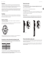 9
9
-
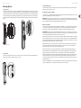 10
10
-
 11
11
-
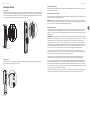 12
12
-
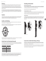 13
13
-
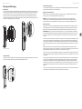 14
14
-
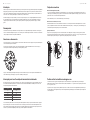 15
15
-
 16
16
-
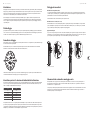 17
17
-
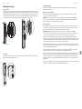 18
18
-
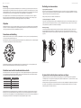 19
19
-
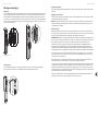 20
20
-
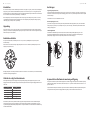 21
21
-
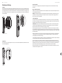 22
22
-
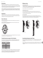 23
23
-
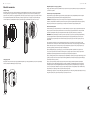 24
24
-
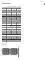 25
25
-
 26
26
-
 27
27
-
 28
28


Tannoy VLS 15 (EN 54) Guide de démarrage rapide
- Catégorie
- Équipement musical supplémentaire
- Taper
- Guide de démarrage rapide
- Ce manuel convient également à
dans d''autres langues
- italiano: Tannoy VLS 15 (EN 54) Guida Rapida
- español: Tannoy VLS 15 (EN 54) Guía de inicio rápido
- Deutsch: Tannoy VLS 15 (EN 54) Schnellstartanleitung
- Nederlands: Tannoy VLS 15 (EN 54) Snelstartgids
- português: Tannoy VLS 15 (EN 54) Guia rápido
- polski: Tannoy VLS 15 (EN 54) Skrócona instrukcja obsługi
- svenska: Tannoy VLS 15 (EN 54) Snabbstartsguide
Documents connexes
-
Tannoy VLS 7 (EN 54) Guide de démarrage rapide
-
Tannoy CPA 5 Guide de démarrage rapide
-
-
-
-
-
-
-
-
Autres documents
-
KlarkTeknik DN9680-MM Guide de démarrage rapide
-
Behringer VP1520 Guide de démarrage rapide
-
Behringer B215XL-WH Guide de démarrage rapide
-
KlarkTeknik DM801 Guide de démarrage rapide
-
Bugera T5 Infinium Guide de démarrage rapide
-
Behringer FCV100 Guide de démarrage rapide
-
Behringer A800 Professional 800-Watt Power Amplifier Mode d'emploi
-
-
TC Electronic K-115 Guide de démarrage rapide
-
Turbosound TQ15 TQ Series Mode d'emploi