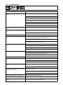
Miller KK128916 Le manuel du propriétaire
- Catégorie
- Système de soudage
- Taper
- Le manuel du propriétaire
Ce manuel convient également à

Visit our website at
www.Miller-
Welds.com
Processes
OM-2211 182 413M
May 1999
Description
Air Plasma Cutting
and Gouging with Spectrum
Plus
Air Carbon Arc Cutting and
Gouging
DC-Gas Tungsten Arc
(DC-TIG) Welding
Shielded Metal Arc
(Stick) Welding
Flux Cored Arc Welding and
Gas Metal Arc Welding (MIG)
Spray Transfer with Voltage-
Sensing Feeder
Multiple Operator Arc Welding Power
Source
Mark VI

Miller Electric manufactures a full line
of welders and welding related equipment.
For information on other quality Miller
products, contact your local Miller distributor
to receive the latest full line catalog or
individual catalog sheets. To locate your nearest
distributor call 1-800-4-A-Miller.
Thank you and congratulations on choosing Miller. Now
you can get the job done and get it done right. We know
you don’t have time to do it any other way.
That’s why when Niels Miller first started building arc
welders in 1929, he made sure his products offered
long-lasting value and superior quality. Like you, his
customers couldn’t afford anything less. Miller products
had to be more than the best they could be. They had to
be the best you could buy.
Today, the people that build and sell Miller products continue the
tradition. They’re just as committed to providing equipment and service
that meets the high standards of quality and value established in 1929.
This Owner’s Manual is designed to help you get the most out of your
Miller products. Please take time to read the Safety precautions. They will
help you protect yourself against potential hazards on the worksite. We’ve
made installation and operation quick and easy.
With Miller you can count on years of reliable
service with proper maintenance. And if for
some reason the unit needs repair, there’s a
Troubleshooting section that will help you
figure out what the problem is. The parts list
will then help you to decide which exact part
you may need to fix the problem. Warranty and
service information for your particular model
are also provided.
Miller is the first welding
equipment manufacturer in
the U.S.A. to be registered
to the ISO 9001 Quality
System Standard.
Working as hard as you
do − every power source
from Miller is backed by
the most hassle-free war-
ranty in the business.
From Miller to You
Miller offers a Technical
Manual which provides
more detailed service and
parts information for your
unit. To obtain a Technical
Manual, contact your local
distributor. Your distributor
can also supply you with
Welding Process Manuals
such as SMAW, GTAW,
GMAW, and GMAW-P.

The following terms are
used interchangeably
throughout this manual:
TIG = GTAW
Stick = SMAW
MIG = GMAW
TABLE OF CONTENTS
SECTION 1 − SAFETY PRECAUTIONS - READ BEFORE USING 1. . . . . . . . . . . . . . . . . . . . . . . . . . . .
1-1. Symbol Usage 1. . . . . . . . . . . . . . . . . . . . . . . . . . . . . . . . . . . . . . . . . . . . . . . . . . . . . . . . . . . . . . . .
1-2. Arc Welding Hazards 1. . . . . . . . . . . . . . . . . . . . . . . . . . . . . . . . . . . . . . . . . . . . . . . . . . . . . . . . . .
1-3. Additional Symbols for Installation, Operation, and Maintenance 3. . . . . . . . . . . . . . . . . . . . . .
1-4. Principal Safety Standards 3. . . . . . . . . . . . . . . . . . . . . . . . . . . . . . . . . . . . . . . . . . . . . . . . . . . . .
1-5. EMF Information 4. . . . . . . . . . . . . . . . . . . . . . . . . . . . . . . . . . . . . . . . . . . . . . . . . . . . . . . . . . . . . .
SECTION 1 − CONSIGNES DE SECURITE − LIRE AVANT UTILISATION 5. . . . . . . . . . . . . . . . . . . . .
1-1. Signification des symboles 5. . . . . . . . . . . . . . . . . . . . . . . . . . . . . . . . . . . . . . . . . . . . . . . . . . . . .
1-2. Dangers relatifs au soudage à l’arc 5. . . . . . . . . . . . . . . . . . . . . . . . . . . . . . . . . . . . . . . . . . . . . .
1-3. Dangers supplémentaires en relation avec l’installation, le fonctionnement
et la maintenance 7. . . . . . . . . . . . . . . . . . . . . . . . . . . . . . . . . . . . . . . . . . . . . . . . . . . . . . . . . . . . .
1-4. Principales normes de sécurité 8. . . . . . . . . . . . . . . . . . . . . . . . . . . . . . . . . . . . . . . . . . . . . . . . . .
1-5. Information sur les champs électromagnétiques 8. . . . . . . . . . . . . . . . . . . . . . . . . . . . . . . . . . . .
SECTION 2 − INSTALLATION 9. . . . . . . . . . . . . . . . . . . . . . . . . . . . . . . . . . . . . . . . . . . . . . . . . . . . . . . . . . .
2-1. Specifications 9. . . . . . . . . . . . . . . . . . . . . . . . . . . . . . . . . . . . . . . . . . . . . . . . . . . . . . . . . . . . . . . .
2-2. Volt-Ampere Curves 9. . . . . . . . . . . . . . . . . . . . . . . . . . . . . . . . . . . . . . . . . . . . . . . . . . . . . . . . . . .
2-3. 60 Hz Duty Cycle And Overheating 10. . . . . . . . . . . . . . . . . . . . . . . . . . . . . . . . . . . . . . . . . . . . . .
2-4. 50 Hz Duty Cycle And Overheating 11. . . . . . . . . . . . . . . . . . . . . . . . . . . . . . . . . . . . . . . . . . . . . .
2-5. Selecting A Location 12. . . . . . . . . . . . . . . . . . . . . . . . . . . . . . . . . . . . . . . . . . . . . . . . . . . . . . . . . . .
2-6. Dimensions And Weights 13. . . . . . . . . . . . . . . . . . . . . . . . . . . . . . . . . . . . . . . . . . . . . . . . . . . . . . .
2-7. 115 Volts AC GFCI Receptacles And Circuit Breakers 13. . . . . . . . . . . . . . . . . . . . . . . . . . . . . . .
2-8. Weld Cable Sizes 14. . . . . . . . . . . . . . . . . . . . . . . . . . . . . . . . . . . . . . . . . . . . . . . . . . . . . . . . . . . . .
2-9. Common Work Cable Sizes 14. . . . . . . . . . . . . . . . . . . . . . . . . . . . . . . . . . . . . . . . . . . . . . . . . . . . .
2-10. Safety Information For Connecting To Weld Output Terminals 15. . . . . . . . . . . . . . . . . . . . . . . . .
2-11. Weld Output Terminals 15. . . . . . . . . . . . . . . . . . . . . . . . . . . . . . . . . . . . . . . . . . . . . . . . . . . . . . . . .
2-12. Standard Module Weld Output Connections For CC SMAW And GTAW Welding
Processes Without A Common Work Terminal 16. . . . . . . . . . . . . . . . . . . . . . . . . . . . . . . . . . . . . . . . .
2-13. Standard Module Weld Output Connections For CC Smaw And GTAW Welding
Processes With A Common Work Terminal 17. . . . . . . . . . . . . . . . . . . . . . . . . . . . . . . . . . . . . . . . . . . .
2-14. Parallel Module Weld Output Connections For CC SMAW Welding Process Without A
Common Work Terminal 18. . . . . . . . . . . . . . . . . . . . . . . . . . . . . . . . . . . . . . . . . . . . . . . . . . . . . . . . . . . .
2-15. Parallel Module Weld Output Connections For CC SMAW Welding Process With A
Common Work Terminal 19. . . . . . . . . . . . . . . . . . . . . . . . . . . . . . . . . . . . . . . . . . . . . . . . . . . . . . . . . . . .
2-16. CC/CV Module Weld Output Connections For CV FCAW Welding Process Without A
Common Work Terminal 20. . . . . . . . . . . . . . . . . . . . . . . . . . . . . . . . . . . . . . . . . . . . . . . . . . . . . . . . . . . .
2-17. CC/CV Module Weld Output Connections For CV FCAW Welding Process With A
Common Work Terminal 21. . . . . . . . . . . . . . . . . . . . . . . . . . . . . . . . . . . . . . . . . . . . . . . . . . . . . . . . . . . .
2-18. Remote 14 Receptacle Information 22. . . . . . . . . . . . . . . . . . . . . . . . . . . . . . . . . . . . . . . . . . . . . . .
2-19. Electrical Service Guide 22. . . . . . . . . . . . . . . . . . . . . . . . . . . . . . . . . . . . . . . . . . . . . . . . . . . . . . . .
2-20. Placing Jumper Links And Connecting Input Power 23. . . . . . . . . . . . . . . . . . . . . . . . . . . . . . . . .
SECTION 3 − OPERATION 24. . . . . . . . . . . . . . . . . . . . . . . . . . . . . . . . . . . . . . . . . . . . . . . . . . . . . . . . . . . . .
3-1. CC Module Controls 24. . . . . . . . . . . . . . . . . . . . . . . . . . . . . . . . . . . . . . . . . . . . . . . . . . . . . . . . . . .
3-2. CC/CV Module Controls 25. . . . . . . . . . . . . . . . . . . . . . . . . . . . . . . . . . . . . . . . . . . . . . . . . . . . . . . .
SECTION 4 − MAINTENANCE AND TROUBLESHOOTING 26. . . . . . . . . . . . . . . . . . . . . . . . . . . . . . . . .
4-1. Routine Maintenance 26. . . . . . . . . . . . . . . . . . . . . . . . . . . . . . . . . . . . . . . . . . . . . . . . . . . . . . . . . .
4-3. Troubleshooting 28. . . . . . . . . . . . . . . . . . . . . . . . . . . . . . . . . . . . . . . . . . . . . . . . . . . . . . . . . . . . . .
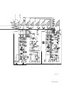
SECTION 5 − ELECTRICAL DIAGRAM 30. . . . . . . . . . . . . . . . . . . . . . . . . . . . . . . . . . . . . . . . . . . . . . . . . . .
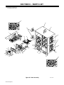
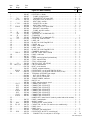
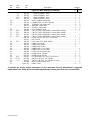
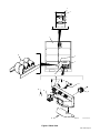
SECTION 6 − PARTS LIST 32. . . . . . . . . . . . . . . . . . . . . . . . . . . . . . . . . . . . . . . . . . . . . . . . . . . . . . . . . . . . . .
OPTIONS AND ACCESSORIES
WARRANTY
OM-2211M
WARNING
This product, when used
for welding or cutting,
produces fumes or
gases which contain
chemicals known to the
State of California to
cause birth defects and,
in some cases, cancer.
(California Health &
Safety Code Section
25249.5 et seq.)


OM-2211 Page 1
SECTION 1 − SAFETY PRECAUTIONS - READ BEFORE USING
som _nd_5/97
1-1. Symbol Usage
Means Warning! Watch Out! There are possible hazards
with this procedure! The possible hazards are shown in
the adjoining symbols.
Y Marks a special safety message.
. Means “Note”; not safety related.
This group of symbols means Warning! Watch Out! possible
ELECTRIC SHOCK, MOVING PARTS, and HOT PARTS hazards.
Consult symbols and related instructions below for necessary actions
to avoid the hazards.
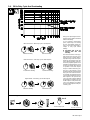
1-2. Arc Welding Hazards
Y The symbols shown below are used throughout this manual to
call attention to and identify possible hazards. When you see
the symbol, watch out, and follow the related instructions to
avoid the hazard. The safety information given below is only
a summary of the more complete safety information found in
the Safety Standards listed in Section NO TAG. Read and fol-
low all Safety Standards.
Y Only qualified persons should install, operate, maintain, and
repair this unit.
Y During operation, keep everybody, especially children, away.
ELECTRIC SHOCK can kill.
Touching live electrical parts can cause fatal shocks
or severe burns. The electrode and work circuit is
electrically live whenever the output is on. The input
power circuit and machine internal circuits are also
live when power is on. In semiautomatic or automatic wire welding, the
wire, wire reel, drive roll housing, and all metal parts touching the
welding wire are electrically live. Incorrectly installed or improperly
grounded equipment is a hazard.
D Do not touch live electrical parts.
D Wear dry, hole-free insulating gloves and body protection.
D Insulate yourself from work and ground using dry insulating mats
or covers big enough to prevent any physical contact with the work
or ground.
D Do not use AC output in damp areas, if movement is confined, or if
there is a danger of falling.
D Use AC output ONLY if required for the welding process.
D If AC output is required, use remote output control if present on
unit.
D Disconnect input power or stop engine before installing or
servicing this equipment. Lockout/tagout input power according to
OSHA 29 CFR 1910.147 (see Safety Standards).
D Properly install and ground this equipment according to its
Owner’s Manual and national, state, and local codes.
D Always verify the supply ground − check and be sure that input
power cord ground wire is properly connected to ground terminal in
disconnect box or that cord plug is connected to a properly
grounded receptacle outlet.
D When making input connections, attach proper grounding conduc-
tor first − double-check connections.
D Frequently inspect input power cord for damage or bare wiring −
replace cord immediately if damaged − bare wiring can kill.
D Turn off all equipment when not in use.
D Do not use worn, damaged, undersized, or poorly spliced cables.
D Do not drape cables over your body.
D If earth grounding of the workpiece is required, ground it directly
with a separate cable − do not use work clamp or work cable.
D Do not touch electrode if you are in contact with the work, ground,
or another electrode from a different machine.
D Use only well-maintained equipment. Repair or replace damaged
parts at once. Maintain unit according to manual.
D Wear a safety harness if working above floor level.
D Keep all panels and covers securely in place.
D Clamp work cable with good metal-to-metal contact to workpiece
or worktable as near the weld as practical.
D Insulate work clamp when not connected to workpiece to prevent
contact with any metal object.
D Do not connect more than one electrode or work cable to any
single weld output terminal.
SIGNIFICANT DC VOLTAGE exists after removal of
input power on inverters.
D Turn Off inverter, disconnect input power, and discharge input
capacitors according to instructions in Maintenance Section
before touching any parts.
Welding produces fumes and gases. Breathing
these fumes and gases can be hazardous to your
health.
FUMES AND GASES can be hazardous.
D Keep your head out of the fumes. Do not breathe the fumes.
D If inside, ventilate the area and/or use exhaust at the arc to remove
welding fumes and gases.
D If ventilation is poor, use an approved air-supplied respirator.
D Read the Material Safety Data Sheets (MSDSs) and the
manufacturer’s instructions for metals, consumables, coatings,
cleaners, and degreasers.
D Work in a confined space only if it is well ventilated, or while
wearing an air-supplied respirator. Always have a trained watch-
person nearby. Welding fumes and gases can displace air and
lower the oxygen level causing injury or death. Be sure the breath-
ing air is safe.
D Do not weld in locations near degreasing, cleaning, or spraying op-
erations. The heat and rays of the arc can react with vapors to form
highly toxic and irritating gases.
D Do not weld on coated metals, such as galvanized, lead, or
cadmium plated steel, unless the coating is removed from the weld
area, the area is well ventilated, and if necessary, while wearing an
air-supplied respirator. The coatings and any metals containing
these elements can give off toxic fumes if welded.

OM-2211 Page 2
Arc rays from the welding process produce intense
visible and invisible (ultraviolet and infrared) rays
that can burn eyes and skin. Sparks fly off from the
weld.
ARC RAYS can burn eyes and skin.
D Wear a welding helmet fitted with a proper shade of filter to protect
your face and eyes when welding or watching (see ANSI Z49.1
and Z87.1 listed in Safety Standards).
D Wear approved safety glasses with side shields under your
helmet.
D Use protective screens or barriers to protect others from flash and
glare; warn others not to watch the arc.
D Wear protective clothing made from durable, flame-resistant mate-
rial (leather and wool) and foot protection.
Welding on closed containers, such as tanks,
drums, or pipes, can cause them to blow up. Sparks
can fly off from the welding arc. The flying sparks, hot
workpiece, and hot equipment can cause fires and
burns. Accidental contact of electrode to metal objects can cause
sparks, explosion, overheating, or fire. Check and be sure the area is
safe before doing any welding.
WELDING can cause fire or explo-
sion.
D Protect yourself and others from flying sparks and hot metal.
D Do not weld where flying sparks can strike flammable material.
D Remove all flammables within 35 ft (10.7 m) of the welding arc. If
this is not possible, tightly cover them with approved covers.
D Be alert that welding sparks and hot materials from welding can
easily go through small cracks and openings to adjacent areas.
D Watch for fire, and keep a fire extinguisher nearby.
D Be aware that welding on a ceiling, floor, bulkhead, or partition can
cause fire on the hidden side.
D Do not weld on closed containers such as tanks, drums, or pipes,
unless they are properly prepared according to AWS F4.1 (see
Safety Standards).
D Connect work cable to the work as close to the welding area as
practical to prevent welding current from traveling long, possibly
unknown paths and causing electric shock and fire hazards.
D Do not use welder to thaw frozen pipes.
D Remove stick electrode from holder or cut off welding wire at
contact tip when not in use.
D Wear oil-free protective garments such as leather gloves, heavy
shirt, cuffless trousers, high shoes, and a cap.
D Remove any combustibles, such as a butane lighter or matches,
from your person before doing any welding.
FLYING METAL can injure eyes.
D Welding, chipping, wire brushing, and grinding
cause sparks and flying metal. As welds cool,
they can throw off slag.
D Wear approved safety glasses with side
shields even under your welding helmet.
BUILDUP OF GAS can injure or kill.
D Shut off shielding gas supply when not in use.
D Always ventilate confined spaces or use
approved air-supplied respirator.
HOT PARTS can cause severe burns.
D Do not touch hot parts bare handed.
D Allow cooling period before working on gun or
torch.
MAGNETIC FIELDS can affect pacemak-
ers.
D Pacemaker wearers keep away.
D Wearers should consult their doctor before
going near arc welding, gouging, or spot
welding operations.
NOISE can damage hearing.
Noise from some processes or equipment can
damage hearing.
D Wear approved ear protection if noise level is
high.
Shielding gas cylinders contain gas under high
pressure. If damaged, a cylinder can explode. Since
gas cylinders are normally part of the welding
process, be sure to treat them carefully.
CYLINDERS can explode if damaged.
D Protect compressed gas cylinders from excessive heat, mechani-
cal shocks, slag, open flames, sparks, and arcs.
D Install cylinders in an upright position by securing to a stationary
support or cylinder rack to prevent falling or tipping.
D Keep cylinders away from any welding or other electrical circuits.
D Never drape a welding torch over a gas cylinder.
D Never allow a welding electrode to touch any cylinder.
D Never weld on a pressurized cylinder − explosion will result.
D Use only correct shielding gas cylinders, regulators, hoses, and fit-
tings designed for the specific application; maintain them and
associated parts in good condition.
D Turn face away from valve outlet when opening cylinder valve.
D Keep protective cap in place over valve except when cylinder is in
use or connected for use.
D Read and follow instructions on compressed gas cylinders,
associated equipment, and CGA publication P-1 listed in Safety
Standards.

OM-2211 Page 3
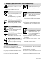
1-3. Additional Symbols for Installation, Operation, and Maintenance
FIRE OR EXPLOSION hazard.
D Do not install or place unit on, over, or near
combustible surfaces.
D Do not install unit near flammables.
D Do not overload building wiring − be sure power supply system is
properly sized, rated, and protected to handle this unit.
FALLING UNIT can cause injury.
D Use lifting eye to lift unit only, NOT running
gear, gas cylinders, or any other accessories.
D Use equipment of adequate capacity to lift and
support unit.
D If using lift forks to move unit, be sure forks are
long enough to extend beyond opposite side of
unit.
OVERUSE can cause OVERHEATING
D Allow cooling period; follow rated duty cycle.
D Reduce current or reduce duty cycle before
starting to weld again.
D Do not block or filter airflow to unit.
STATIC (ESD) can damage PC boards.
D Put on grounded wrist strap BEFORE handling
boards or parts.
D Use proper static-proof bags and boxes to
store, move, or ship PC boards.
MOVING PARTS can cause injury.
D Keep away from moving parts.
D Keep away from pinch points such as drive
rolls.
WELDING WIRE can cause injury.
D Do not press gun trigger until instructed to do
so.
D Do not point gun toward any part of the body,
other people, or any metal when threading
welding wire.
MOVING PARTS can cause injury.
D Keep away from moving parts such as fans.
D Keep all doors, panels, covers, and guards
closed and securely in place.
H.F. RADIATION can cause interference.
D High-frequency (H.F.) can interfere with radio
navigation, safety services, computers, and
communications equipment.
D Have only qualified persons familiar with
electronic equipment perform this installation.
D The user is responsible for having a qualified electrician prompt-
ly correct any interference problem resulting from the installa-
tion.
D If notified by the FCC about interference, stop using the
equipment at once.
D Have the installation regularly checked and maintained.
D Keep high-frequency source doors and panels tightly shut, keep
spark gaps at correct setting, and use grounding and shielding to
minimize the possibility of interference.
ARC WELDING can cause interference.
D Electromagnetic energy can interfere with
sensitive electronic equipment such as
computers and computer-driven equipment
such as robots.
D Be sure all equipment in the welding area is
electromagnetically compatible.
D To reduce possible interference, keep weld cables as short as
possible, close together, and down low, such as on the floor.
D Locate welding operation 100 meters from any sensitive elec-
tronic equipment.
D Be sure this welding machine is installed and grounded
according to this manual.
D If interference still occurs, the user must take extra measures
such as moving the welding machine, using shielded cables,
using line filters, or shielding the work area.
1-4. Principal Safety Standards
Safety in Welding and Cutting, ANSI Standard Z49.1, from American
Welding Society, 550 N.W. LeJeune Rd, Miami FL 33126
Safety and Health Standards, OSHA 29 CFR 1910, from Superinten-
dent of Documents, U.S. Government Printing Office, Washington, D.C.
20402.
Recommended Safe Practices for the Preparation for Welding and Cut-
ting of Containers That Have Held Hazardous Substances, American
Welding Society Standard AWS F4.1, from American Welding Society,
550 N.W. LeJeune Rd, Miami, FL 33126
National Electrical Code, NFPA Standard 70, from National Fire Protec-
tion Association, Batterymarch Park, Quincy, MA 02269.
Safe Handling of Compressed Gases in Cylinders, CGA Pamphlet P-1,
from Compressed Gas Association, 1235 Jefferson Davis Highway,
Suite 501, Arlington, VA 22202.
Code for Safety in Welding and Cutting, CSA Standard W117.2, from
Canadian Standards Association, Standards Sales, 178 Rexdale
Boulevard, Rexdale, Ontario, Canada M9W 1R3.
Safe Practices For Occupation And Educational Eye And Face
Protection, ANSI Standard Z87.1, from American National Standards
Institute, 1430 Broadway, New York, NY 10018.
Cutting And Welding Processes, NFPA Standard 51B, from National
Fire Protection Association, Batterymarch Park, Quincy, MA 02269.

OM-2211 Page 4
1-5. EMF Information
Considerations About Welding And The Effects Of Low Frequency
Electric And Magnetic Fields
Welding current, as it flows through welding cables, will cause electro-
magnetic fields. There has been and still is some concern about such
fields. However, after examining more than 500 studies spanning 17
years of research, a special blue ribbon committee of the National
Research Council concluded that: “The body of evidence, in the
committee’s judgment, has not demonstrated that exposure to power-
frequency electric and magnetic fields is a human-health hazard.”
However, studies are still going forth and evidence continues to be
examined. Until the final conclusions of the research are reached, you
may wish to minimize your exposure to electromagnetic fields when
welding or cutting.
To reduce magnetic fields in the workplace, use the following
procedures:
1. Keep cables close together by twisting or taping them.
2. Arrange cables to one side and away from the operator.
3. Do not coil or drape cables around your body.
4. Keep welding power source and cables as far away from opera-
tor as practical.
5. Connect work clamp to workpiece as close to the weld as possi-
ble.
About Pacemakers:
Pacemaker wearers consult your doctor first. If cleared by your doctor,
then following the above procedures is recommended.

OM-2211 Page 5
SECTION 1 − CONSIGNES DE SECURITE − LIRE AVANT UTILISATION
som _nd_Fre 4/97
1-1. Signification des symboles
Signifie Mise en garde ! Soyez vigilant ! Cette procédure
présente des risques de danger ! Ceux-ci sont identifiés
par des symboles adjacents aux directives.
Y Identifie un message de sécurité particulier.
. Signifie NOTA ; n’est pas relatif à la sécurité.
Ce groupe de symboles signifie Mise en garde ! Soyez vigilant ! Il y a des
risques de danger reliés aux CHOCS ÉLECTRIQUES, aux PIÈCES EN
MOUVEMENT et aux PIÈCES CHAUDES. Reportez-vous aux symboles
et aux directives ci-dessous afin de connaître les mesures à prendre pour
éviter tout danger.
1-2. Dangers relatifs au soudage à l’arc
Y Les symboles présentés ci-après sont utilisés tout au long du
présent manuel pour attirer votre attention et identifier les risques
de danger. Lorsque vous voyez un symbole, soyez vigilant et
suivez les directives mentionnées afin d’éviter tout danger. Les
consignes de sécurité présentées ci-après ne font que résumer
l’information contenue dans les normes de sécurité énumérées
à la section 1-5. Veuillez lire et respecter toutes ces normes de
sécurité.
Y L’installation, l’utilisation, l’entretien et les réparations ne doi-
vent être confiés qu’à des personnes qualifiées.
Y Au cours de l’utilisation, tenir toute personne à l’écart et plus par-
ticulièrement les enfants.
UN CHOC ÉLECTRIQUE peut tuer.
Un simple contact avec des pièces électriques peut
provoquer une électrocution ou des blessures graves.
L’électrode et le circuit de soudage sont sous tension
dès que l’appareil est sur ON. Le circuit d’entrée et les
circuits internes de l’appareil sont également sous
tension à ce moment-là. En soudage semi-automatique ou automatique,
le fil, le dévidoir, le logement des galets d’entraînement et les pièces
métalliques en contact avec le fil de soudage sont sous tension. Des
matériels mal installés ou mal mis à la terre présentent un danger.
D Ne jamais toucher les pièces électriques sous tension.
D Porter des gants et des vêtements de protection secs ne comportant
pas de trous.
D S’isoler de la pièce et de la terre au moyen de tapis ou d’autres
moyens isolants suffisamment grands pour empêcher le contact phy-
sique éventuel avec la pièce ou la terre.
D Ne pas se servir de source électrique àcourant électrique dans les zones
humides, dans les endroits confinés ou là où on risque de tomber.
D Se servir d’une source électrique àcourant électrique UNIQUEMENT si le
procédé de soudage le demande.
D Si l’utilisation d’une source électrique àcourant électrique s’avère néces-
saire, se servir de la fonction de télécommande si l’appareil en est équipé.
D Couper l’alimentation ou arrêter le moteur avant de procéder à l’instal-
lation, à la réparation ou à l’entretien de l’appareil. Déverrouiller
l’alimentation selon la norme OSHA 29 CFR 1910.147 (voir normes de
sécurité).
D Installer et mettre à la terre correctement cet appareil conformément à
son manuel d’utilisation et aux codes nationaux, provinciaux et
municipaux.
D Toujours vérifier la terre du cordon d’alimentation − Vérifier et s’assu-
rer que le fil de terre du cordon d’alimentation est bien raccordé à la
borne de terre du sectionneur ou que la fiche du cordon est raccordée
à une prise correctement mise à la terre.
D En effectuant les raccordements d’entrée fixer d’abord le conducteur
de mise à la terre approprié et contre-vérifier les connexions.
D Vérifier fréquemment le cordon d’alimentation pour voir s’il n’est pas
endommagé ou dénudé − remplacer le cordon immédiatement s’il est
endommagé − un câble dénudé peut provoquer une électrocution.
D Mettre l’appareil hors tension quand on ne l’utilise pas.
D Ne pas utiliser des câbles usés, endommagés, de grosseur insuffi-
sante ou mal épissés.
D Ne pas enrouler les câbles autour du corps.
D Si la pièce soudée doit être mise à la terre, le faire directement avec un
câble distinct − ne pas utiliser le connecteur de pièce ou le câble de
retour.
D Ne pas toucher l’électrode quand on est en contact avec la pièce, la
terre ou une électrode provenant d’une autre machine.
D N’utiliser qu’un matériel en bon état. Réparer ou remplacer sur-le-
champ les pièces endommagées. Entretenir l’appareil conformément
à ce manuel.
D Porter un harnais de sécurité quand on travaille en hauteur.
D Maintenir solidement en place tous les panneaux et capots.
D Fixer le câble de retour de façon à obtenir un bon contact métal-métal
avec la pièce à souder ou la table de travail, le plus près possible de la
soudure.
D Isoler la pince de masse quand pas mis à la pièce pour éviter le contact
avec tout objet métallique.
Il y a DU COURANT CONTINU IMPORTANT dans les
convertisseurs après la suppression de l’alimenta-
tion électrique.
D Arrêter les convertisseurs, débrancher le courant électrique, et dé-
charger les condensateurs d’alimentation selon les instructions
indiquées dans la partie entretien avant de toucher les pièces.
Le soudage génère des fumées et des gaz. Leur
inhalation peut être dangereux pour votre santé.
D Eloigner votre tête des fumées. Ne pas respirer
les fumées.
D A l’intérieur, ventiler la zone et/ou utiliser un échappement au niveau
de l’arc pour l’évacuation des fumées et des gaz de soudage.
D Si la ventilation est insuffisante, utiliser un respirateur à alimenta-
tion d’air homologué.
D Lire les spécifications de sécurité des matériaux (MSDSs) et les
instructions du fabricant concernant les métaux, les consomma-
bles, les revêtements, les nettoyants et les dégraisseurs.
D Travailler dans un espace fermé seulement s’il est bien ventilé ou en
portant un respirateur à alimentation d’air. Demander toujours à un
surveillant dûment formé de se tenir à proximité. Des fumées et des
gaz de soudage peuvent déplacer l’air et abaisser le niveau d’oxy-
gène provoquant des blessures ou des accidents mortels. S’assu-
rer que l’air de respiration ne présente aucun danger.
D Ne pas souder dans des endroits situés à proximité d’opérations de
dégraissage, de nettoyage ou de pulvérisation. La chaleur et les
rayons de l’arc peuvent réagir en présence de vapeurs et former des
gaz hautement toxiques et irritants.
D Ne pas souder des métaux munis d’un revêtement, tels que l’acier
galvanisé, plaqué en plomb ou au cadmium à moins que le revête-
ment n’ait été enlevé dans la zone de soudure, que l’endroit soit bien
ventilé, et si nécessaire, en portant un respirateur à alimentation
d’air. Les revêtements et tous les métaux renfermant ces éléments
peuvent dégager des fumées toxiques en cas de soudage.
LES FUMÉES ET LES GAZ peuvent
être dangereux.

OM-2211 Page 6
Le rayonnement de l’arc du procédé de soudage
génère des rayons visibles et invisibles intenses
(ultraviolets et infrarouges) susceptibles de provoquer
des brûlures dans les yeux et sur la peau. Des étincelles sont projetées
pendant le soudage.
LES RAYONS DE L’ARC peuvent pro-
voquer des brûlures dans les yeux et
sur la peau.
D Porter un casque de soudage muni d’un écran de filtre approprié pour
protéger votre visage et vos yeux pendant le soudage ou pour regar-
der (voir ANSI Z49.1 et Z87.1 énuméré dans les normes de sécurité).
D Porter des protections approuvés pour les oreilles si le niveau sondre est
trop élevé.
D Utiliser des écrans ou des barrières pour protéger des tiers de l’éclair
et de l’éblouissement; demander aux autres personnes de ne pas re-
garder l’arc.
D Porter des vêtements de protection constitué dans une matière dura-
ble, résistant au feu (cuir ou laine) et une protection des pieds.
Le soudage effectué sur des conteneurs fermés tels
que des réservoirs, tambours ou des conduites peut
provoquer leur éclatement. Des étincelles peuvent être
projetées de l’arc de soudure. La projection d’étincel-
les, des pièces chaudes et des équipements chauds peut provoquer des
incendies et des brûlures. Le contact accidentel de l’électrode avec des
objets métalliques peut provoquer des étincelles, une explosion, un
surchauffement ou un incendie. Avant de commencer le soudage, vérifier
et s’assurer que l’endroit ne présente pas de danger.
LE SOUDAGE peut provoquer un
incendie ou une explosion.
D Se protéger et d’autres personnes de la projection d’étincelles et de
métal chaud.
D Ne pas souder dans un endroit là où des étincelles peuvent tomber sur
des substances inflammables.
D Déplacer toutes les substances inflammables à une distance de 10,7
m de l’arc de soudage. En cas d’impossibilité les recouvrir soigneuse-
ment avec des protections homologués.
D Des étincelles et des matériaux chauds du soudage peuvent facile-
ment passer dans d’autres zones en traversant de petites fissures et
des ouvertures.
D Surveiller tout déclenchement d’incendie et tenir un extincteur à proxi-
mité.
D Le soudage effectué sur un plafond, plancher, paroi ou séparation
peut déclencher un incendie de l’autre côté.
D Ne pas effectuer le soudage sur des conteneurs fermés tels que des
réservoirs, tambours, ou conduites, à moins qu’ils n’aient été prépa-
rés correctement conformément à AWS F4.1 (voir les normes de
sécurité).
D Brancher le câble sur la pièce le plus près possible de la zone de sou-
dage pour éviter le transport du courant sur une longue distance par
des chemins inconnus éventuels en provoquant des risques d’élec-
trocution et d’incendie.
D Ne pas utiliser le poste de soudage pour dégeler des conduites ge-
lées.
D En cas de non utilisation, enlever la baguette d’électrode du porte-
électrode ou couper le fil à la pointe de contact.
D Porter des vêtements de protection dépourvus d’huile tels que des
gants en cuir, une chemise en matériau lourd, des pantalons sans re-
vers, des chaussures hautes et un couvre chef.
D Avant de souder, retirer toute substance combustible de vos poches
telles qu’un allumeur au butane ou des allumettes.
DES PARTICULES VOLANTES
peuvent blesser les yeux.
D Le soudage, l’écaillement, le passage de la pièce
à la brosse en fil de fer, et le meulage génèrent
des étincelles et des particules métalliques vo-
lantes. Pendant la période de refroidissement des soudures, elles ris-
quent de projeter du laitier.
D Porter des lunettes de sécurité avec écrans latéraux ou un écran facial.
LES ACCUMULATIONS DE GAZ ris-
quent de provoquer des blessures ou
même la mort.
D Fermer l’alimentation du gaz protecteur en cas de
non utilisation.
D Veiller toujours à bien aérer les espaces confinés ou se servir d’un respi-
rateur d’adduction d’air homologué.
DES PIÈCES CHAUDES peuvent pro-
voquer des brûlures graves.
D Ne pas toucher des parties chaudes à mains nues
D Prévoir une période de refroidissement avant
d’utiliser le pistolet ou la torche.
LES CHAMPS MAGNÉTIQUES peuvent
affecter les stimulateurs cardiaques.
D Porteurs de stimulateur cardiaque, restez à distance.
D Les porteurs d’un stimulateur cardiaque doivent
d’abord consulter leur médecin avant de s’approcher
des opérations de soudage à l’arc, de gougeage ou
de soudage par points.
LE BRUIT peut affecter l’ouïe.
Le bruit des processus et des équipements peut affecter
l’ouïe.
D Porter des protections approuvés pour les oreilles si
le niveau sondre est trop élevé.
Des bouteilles de gaz protecteur contiennent du gaz
sous haute pression. Si une bouteille est endomma-
gée, elle peut exploser. Du fait que les bouteilles de gaz
font normalement partie du procédé de soudage, les
manipuler avec précaution.
D Protéger les bouteilles de gaz comprimé d’une chaleur excessive,
des chocs mécaniques, du laitier, des flammes ouvertes, des étin-
celles et des arcs.
D Placer les bouteilles debout en les fixant dans un support stationnai-
re ou dans un porte-bouteilles pour les empêcher de tomber ou de
se renverser.
D Tenir les bouteilles éloignées des circuits de soudage ou autres cir-
cuits électriques.
D Ne jamais placer une torche de soudage sur une bouteille à gaz.
D Une électrode de soudage ne doit jamais entrer en contact avec une
bouteille.
D Ne jamais souder une bouteille pressurisée − risque d’explosion.
D Utiliser seulement des bouteilles de gaz protecteur, régulateurs,
tuyaux et raccords convenables pour cette application spécifique;
les maintenir ainsi que les éléments associés en bon état.
D Ne pas tenir la tête en face de la sortie en ouvrant la soupape de la
bouteille.
D Maintenir le chapeau de protection sur la soupape, sauf en cas d’uti-
lisation ou de branchement de la bouteille.
D Lire et suivre les instructions concernant les bouteilles de gaz com-
primé, les équipements associés et les publications P-1 CGA énu-
mérées dans les normes de sécurité.
Si des BOUTEILLES sont endomma-
gées, elles pourront exploser.

OM-2211 Page 7
1-3. Dangers supplémentaires en relation avec l’installation, le fonctionnement
et la maintenance
Risque D’INCENDIE OU
D’EXPLOSION.
D Ne pas placer l’appareil sur, au-dessus ou à proxi-
mité de surfaces infllammables.
D Ne pas installer l’appareil à proximité de produits inflammables
D Ne pas surcharger l’installation électrique − s”assurer que l’alimen-
tation est correctement dimensionné et protégé avant de mettre
l’appareil en service.
LA CHUTE DE L’APPAREIL peut
blesser.
D Utiliser l’anneau de levage uniquement pour sou-
lever l’appareil, NON PAS les chariot, les bouteil-
les de gaz ou tout autre accessoire.
D Utiliser un engin d’une capacité appropriée pour
soulever l’appareil.
D En utilisant des fourches de levage pour déplacer l’unité, s’assurer
que les fourches sont suffisamment longues pour dépasser du côté
opposé de l’appareil.
L’EMPLOI EXCESSIF peut
SURCHAUFFER L’ÉQUIPEMENT.
D Prévoir une période de refroidissement, respec-
ter le cycle opératoire nominal.
D Réduire le courant ou le cycle opératoire avant de
recommancer le soudage.
D Ne pas obstruer les passages d’air du poste.
LES CHARGES ÉLECTROSTATI-
QUES peuvent endommager les cir-
cuits imprimés.
D Établir la connexion avec la barrette de terre
avant de manipuler des cartes ou des pièces.
D Utiliser des pochettes et des boîtes antistatiques
pour stocker, déplacer ou expédier des cartes de
circuits imprimes.
DES ORGANES MOBILES peuvent
provoquer des blessures.
D Ne pas s’approcher des organes mobiles.
D Ne pas s’approcher des points de coincement
tels que des rouleaux de commande.
LES FILS DE SOUDAGE peuvent pro-
voquer des blessures.
D Ne pas appuyer sur la gachette avant d’en avoir
reçu l’instruction.
D Ne pas diriger le pistolet vers soi, d’autres person-
nes ou toute pièce mécanique en engageant le fil
de soudage.
DES ORGANES MOBILES peuvent
provoquer des blessures.
D Rester à l’écart des organes mobiles comme le
ventilateur.
D Maintenir fermés et fixement en place les portes,
panneaux, recouvrements et dispositifs de
protection.
LE RAYONNEMENT HAUTE FRÉ-
QUENCE (H.F.) risque de provoquer
des interférences.
D Le rayonnement haute frequence peut provoquer
des interférences avec les équipements de ra-
dio−navigation et de communication, les services
de sécurité et les ordinateurs.
D Demander seulement à des personnes qualifiées familiarisées
avec des équipements électroniques de faire fonctionner l’installa-
tion.
D L’utilisateur est tenu de faire corriger rapidement par un électricien
qualifié les interférences résultant de l’installation.
D Si le FCC signale des interférences, arrêter immédiatement l’appa-
reil.
D Effectuer régulièrement le contrôle et l’entretien de l’installation.
D Maintenir soigneusement fermés les portes et les panneaux des
sources de haute fréquence, maintenir les éclateurs à une distance
correcte et utiliser une terre et et un blindage pour réduire les interfé-
rences éventuelles.
LE SOUDAGE À L’ARC risque de
provoquer des interférences.
D L’énergie électromagnétique risque de provoquer
des interférences pour l’équipement électronique
sensible tel que les ordinateurs et l’équipement
commandé par ordinateur tel que les robots.
D Veiller à ce que tout l’équipement de la zone de soudage soit com-
patible électromagnétiquement.
D Pour réduire la possibilité d’interférence, maintenir les câbles de
soudage aussi courts que possible, les grouper, et les poser aussi
bas que possible (ex. par terre).
D Veiller à souder à une distance de 100 mètres de tout équipement
électronique sensible.
D Veiller à ce que ce poste de soudage soit posé et mis à la terre
conformément à ce mode d’emploi.
D En cas d’interférences après avoir pris les mesures précédentes, il
incombe à l’utilisateur de prendre des mesures supplémentaires tel-
les que le déplacement du poste, l’utilisation de câbles blindés, l’uti-
lisation de filtres de ligne ou la pose de protecteurs dans la zone de
travail.
LES CHAMPS MAGNÉTIQUES peuvent
affecter les stimulateurs cardiaques.
D Porteurs de stimulateur cardiaque, restez à dis-
tance.
D Les porteurs d’un stimulateur cardiaque doivent
d’abord consulter leur médecin avant de s’appro-
cher des opérations de soudage à l’arc, de gou-
geage ou de soudage par points.

OM-2211 Page 8
1-4. Principales normes de sécurité
Safety in Welding and Cutting, norme ANSI Z49.1, de l’American Wel-
ding Society, 550 N.W. Lejeune Rd, Miami FL 33126
Safety and Health Sandards, OSHA 29 CFR 1910, du Superintendent
of Documents, U.S. Government Printing Office, Washington, D.C.
20402.
Recommended Safe Practice for the Preparation for Welding and Cut-
ting of Containers That Have Held Hazardous Substances, norme AWS
F4.1, de l’American Welding Society, 550 N.W. Lejeune Rd, Miami FL
33126
National Electrical Code, NFPA Standard 70, de la National Fire Protec-
tion Association, Batterymarch Park, Quincy, MA 02269.
Safe Handling of Compressed Gases in Cylinders, CGA Pamphlet P-1,
de la Compressed Gas Association, 1235 Jefferson Davis Highway,
Suite 501, Arlington, VA 22202.
Règles de sécurité en soudage, coupage et procédés connexes, norme
CSA W117.2, de l’Association canadienne de normalisation, vente de
normes, 178 Rexdale Boulevard, Rexdale (Ontario) Canada M9W 1R3.
Safe Practices For Occupation And Educational Eye And Face Protec-
tion, norme ANSI Z87.1, de l’American National Standards Institute,
1430 Broadway, New York, NY 10018.
Cutting and Welding Processes, norme NFPA 51B, de la National Fire
Protection Association, Batterymarch Park, Quincy, MA 02269.
1-5. Information sur les champs électromagnétiques
Données sur le soudage électrique et sur les effets, pour l’organisme,
des champs magnétiques basse fréquence
L’extrait suivant est tiré des conclusions générales du document intitulé
Biological Effects of Power Frequency Electric & Magnetic Fields −
Background Paper, OTA−BP−E−53 (Washington DC : U.S. Govern-
ment Printing Office, mai 1989), publié par le Office of Technology
Assessment du Congrès américain : «... il existe maintenant d’abon-
dantes données scientifiques compilées à la suite d’expériences sur la
cellule ou d’études sur des animaux et des humains, qui montrent clai-
rement que les champs électromagnétiques basse fréquence peuvent
avoir des effets sur l’organisme et même y produire des transforma-
tions. Même s’il s’agit de travaux de très grande qualité, les résultats
sont complexes. Cette démarche scientifique ne nous permet pas
d’établir un tableau d’ensemble cohérent. Pire encore, elle ne nous per-
met pas de tirer des conclusions finales concernant les risques
éventuels, ni d’offrir des conseils sur les mesures à prendre pour rédui-
re sinon éliminer les risques éventuels». (Traduction libre)
Afin de réduire les champs électromagnétiques dans l’environnement
de travail, respecter les consignes suivantes :
1 Garder les câbles ensembles en les torsadant ou en les
attachant avec du ruban adhésif.
2 Mettre tous les câbles du côté opposé de l’opérateur.
3 Ne pas courber pas et ne pas entourer pas les câbles autour de
vous.
4 Garder le poste de soudage et les câbles le plus loin possible de
vous.
5 Relier la pince de masse le plus près possible de la zone de
soudure.
Consignes relatives aux stimulateurs cardiaques :
Les consignes mentionnées précédemment font partie de celles desti-
nées aux personnes ayant recours à un stimulateur cardiaque. Veuillez
consulter votre médecin pour obtenir plus de détails.

OM-2211 Page 9
SECTION 2 − INSTALLATION
. A six module unit is illustrated throughout this Owner’s manual. Four module units are available. Installation and operation is similar to that of a
six module unit.
2-1. Specifications
Rated Output At 44 Volts DC
DC Amperage/Voltage
Range
Max. Open
Circuit Voltage
Rated Output At 44 Volts DC
DC Amperage/Voltage
Range
Max. Open
Circuit Voltage
Six Or
Four
Each Module Main Transformer
20 − 315 A In CC Mode
75 VDC In CC
Mode
Four
Module
Units
60 Or 50 Hz
250 A @ 60% Duty
60 Hz
750 A @ 100% Duty Cycle
50 Hz
750 A @ 60% Duty Cycle
20 − 315 A In CC Mode
10 − 30 V In CV Mode
With CC/CV Module
Mode
38 VDC In CV
Mode With CC/CV
Module
Units
250 A @ 60% Duty
Cycle
750 A @ 100% Duty Cycle
1500 A @ 25% Duty Cycle
750 A @ 60% Duty Cycle
1160 A @ 25% Duty Cycle
With CC/CV Module
Mode With CC/CV
Module
Amps Input At Rated Output of 750 A,
50 Or 60 Hz, Three-Phase
230 V 380 400 415 440 460 V 575 V KVA KW
164
12.5*
97
7.5*
92
7*
91
7*
84
6.5*
82.5
6.2*
66.1
5*
65.2
5*
41.9
3.2*
164
12.5*
97
7.5*
92
7*
91
7*
84
6.5*
82.5
6.2*
66.1
5*
65.2
5*
41.9
3.2*
* While idling
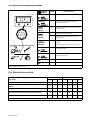
2-2. Volt-Ampere Curves
SB-184 158 / SB-190 886
The volt-ampere curves show the
normal minimum and maximum
voltage and amperage output capa-
bilities of the welding power source.
Curves of other settings fall be-
tween the curves shown.
CC Mode
CV Mode With
CC/CV Module

OM-2211 Page 10
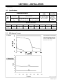
2-3. 60 Hz Duty Cycle And Overheating
2-1/2 Minutes Welding 7-1/2 Minutes Resting
6 Minutes Welding 4 Minutes Resting
Continuous Welding
Duty Cycle is percentage of 10 min-
utes that unit can weld at rated load
without overheating.
If unit overheats, thermostat(s)
opens, output stops, and cooling
fan runs. Wait fifteen minutes for
unit to cool. Reduce amperage or
voltage, or duty cycle before
welding.
Y Exceeding duty cycle can
damage unit and void
warranty.
The main transformer of the poly-
weld system has dual duty cycle
ratings, each for a specific amper-
age output range. If the unit is oper-
ated in the 750 ampere range, the
unit is rated at 100% duty cycle.
This means the polyweld system
can be operated at 750 amperes
continuously. When the unit is oper-
ated in the 1500 ampere range, it is
rated at 25% duty cycle.
The sum of the outputs of each
module should not exceed the rated
duty cycle of the main transformer.
For example, the polyweld system
can be safely operated at a load of
800 amperes at 80 percent duty
cycle. This value could be obtained
by operating four modules at a load
of 200 amperes at 80 percent duty
cycle, or by operating six modules
at a load of 135 amperes at 80 per-
cent duty cycle.
Overheating
0
15
A or V
OR
Reduce Duty Cycle
Minutes
duty1 4/95 − SB-184 107-C
Main Transformer − 25% Duty Cycle at 1500 Amperes
Single Module − 60% Duty Cycle at 250 Amperes
Main Transformer − 100% Duty Cycle at 750 Amperes

OM-2211 Page 11
2-4. 50 Hz Duty Cycle And Overheating
2-1/2 Minutes Welding 7-1/2 Minutes Resting
6 Minutes Welding 4 Minutes Resting
Duty Cycle is percentage of 10 min-
utes that unit can weld at rated load
without overheating.
If unit overheats, thermostat(s)
opens, output stops, and cooling
fan runs. Wait fifteen minutes for
unit to cool. Reduce amperage or
voltage, or duty cycle before
welding.
Y Exceeding duty cycle can
damage unit and void
warranty.
The main transformer of the poly-
weld system has dual duty cycle
ratings, each for a specific amper-
age output range. If the unit is oper-
ated in the 750 ampere range, the
unit is rated at 60% duty cycle. This
means the polyweld system can be
operated at 750 amperes for six out
of every ten minutes. When the unit
is operated in the 1160 ampere
range, it is rated at 25% duty cycle.
The sum of the outputs of each
module should not exceed the rated
duty cycle of the main transformer.
For example, the polyweld system
can be safely operated at a load of
650 amperes at 80 percent duty
cycle. This value could be obtained
by operating four modules at a load
of 165 amperes at 80 percent duty
cycle, or by operating six modules
at a load of 110 amperes at 80 per-
cent duty cycle.
Overheating
0
15
A or V
OR
Reduce Duty Cycle
Minutes
duty1 4/95 − SB-193 918
Main Transformer − 25% Duty Cycle at 1160 Amperes
Single Module − 60% Duty Cycle at 250 Amperes
6 Minutes Welding 4 Minutes Resting
Main Transformer − 60% Duty Cycle at 750 Amperes

OM-2211 Page 12
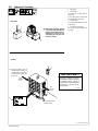
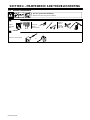
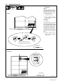
2
-5. Selecting A Location
loc_1 3/96 Ref. ST-801 627-A
1 Lifting Eye
2 Lifting Forks
Use lifting eye or lifting forks to
move unit.
If using lifting forks, extend forks
beyond opposite side of unit.
3 Rating Label
Use rating label to determine input
power needs.
4 Line Disconnect Device
Locate unit near correct input pow-
er supply.
OR
1
3
Movement
Location
2
4
Do not block airflow
to sides of unit.
. Special installation may be
required where gasoline or
volatile liquids are present −
see NEC Article 511 or CEC
Section 20.
Y High center of gravity − always
securely tie down unit with ade-
quate chains or other proper re-
straints when moving to pre-
vent tipping. Do not place unit
where it could tip.
36 in
(920mm)
36 in
(920mm)
Air Out
Air In
S-183 992
IMPORTANT!
This unit contains fan blades
with different airflow directions
to provide proper cooling of
components. Consult Owner’s
Manual for correct Part No.
and location.

OM-2211 Page 13
2-6. Dimensions And Weights
Dimensions
Dimensions
Height* 65 in (1651 mm)
Width 56-3/4 in (1442 mm)
Depth 34-1/4 in (870 mm)
*72 in (1829 mm) with lifting eye
Weight
Each Module Four Unit Module Six Module Unit
125 lb (57 kg) 1575 lb (718 kg)
60 Hz − 1825 lb (828 kg)
50 Hz − 1870 lb (848 kg)
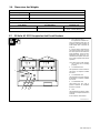
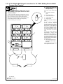
2
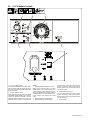
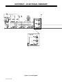
-7. 115 Volts AC GFCI Receptacles And Circuit Breakers
Ref. ST-801 627-A
1 115 V 15 A AC GFCI
Receptacles RC9 And RC10
These receptacles supply up to 15
amperes of 115 volts ac power. In
50 Hz models, RC9 is 220 volts, 15
amps AC.
If a ground fault is detected, the
GFCI Reset button pops out and
the circuit opens to disconnect the
faulty equipment. Check for dam-
aged tools, cords, plugs, etc. con-
nected to the receptacle. Press but-
ton to reset receptacle and resume
operation.
. At least once a month, test but-
ton to verify GFCI is working
properly.
2 Circuit Breaker CB1
CB1 protects RC9 from overload. If
CB1 opens, no output is available
from RC9.
3 Circuit Breaker CB2
CB2 protects RC10 from overload.
If CB2 opens, no output is available
from RC10.
4 Circuit Breaker CB3
CB3 protects the 115 volts ac
portion of Remote 14 receptacle
RC8 from overload.
5 CB4
CB4 protects the 24 volts ac portion
of Remote 14 receptacle RC8 from
overload.
Press button to reset breaker.
1
2345

OM-2211 Page 14
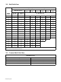
2-8. Weld Cable Sizes
Total Cable (Copper) Length In Weld Circuit Not Exceeding
100 ft (30 m) Or Less
150 ft
(45 m)
200 ft
(60 m)
250 ft
(70 m)
300 ft
(90 m)
350 ft
(105 m)
400 ft
(120 m)
Welding
Amperes
10 − 60%
Duty Cycle
60 − 100% Duty
Cycle
10 − 100% Duty Cycle
100 4 4 4 3 2 1 1/0 1/0
150 3 3 2 1 1/0 2/0 3/0 3/0
200 3 2 1 1/0 2/0 3/0 4/0 4/0
250 2 1 1/0 2/0 3/0 4/0 2-2/0 2-2/0
300 1 1/0 2/0 3/0 4/0 2-2/0 2-3/0 2-3/0
350 1/0 2/0 3/0 4/0 2-2/0 2-3/0 2-3/0 2-4/0
400 1/0 2/0 3/0 4/0 2-2/0 2-3/0 2-4/0 2-4/0
500 2/0 3/0 4/0 2-2/0 2-3/0 2-4/0 3-3/0 3-3/0
600 3/0 4/0 2-2/0 2-3/0 2-4/0 3-3/0 3-4/0 3-4/0
700 4/0 2-2/0 2-3/0 2-4/0 3-3/0 3-4/0 3-4/0 4-4/0
800 4/0 2-2/0 2-3/0 2-4/0 3-4/0 3-4/0 4-4/0 4-4/0
900 2-2/0 2-3/0 2-4/0 3-3/0 3-4/0 4-4/0 4-4/0
1000 2-2/0 2-3/0 2-4/0 3-3/0 4-3/0 4-4/0
1250 2-3/0 2-4/0 3-3/0 4-3/0 4-4/0
1500 2-4/0 3-3/0 3-4/0 4-4/0
1750 750 1000 2-750 2-1000 2-1000
Weld cable size (AWG) is based on either a 4 volts or less drop or a current density of at least 300 circular mils per ampere. Contact your dis-
tributor for the mm
2
equivalent weld cable sizes.
2-9. Common Work Cable Sizes
Common Work Cable Sizes At Main Transformer
Rated Welding Current
Cable Length Cable Size
50 ft (15 m) 2 No. 3/0
100 ft (30.5 m) 2 No. 4/0
150 ft (46 m) 3 No. 3/0
200 ft (61 m) 3 No. 4/0

OM-2211 Page 15
2
-10. Safety Information For Connecting To Weld Output Terminals
Y ELECTRIC SHOCK can kill; ARCING can burn skin or damage electrical connections.
Turn Off welding power source before making any weld output connections.
Do not connect welding output of different polarities to the same structure.
See ANSI Z49.1 and OSHA Title 29, Chapter XVII, Part 1910, Subpart Q (addresses at beginning of manual).
When using Common Work terminal, all connections to the Common Work terminal must be of the same polarity. Also, when welding on the same
work piece, all connections to the work piece must be of the same polarity.
Remove jumper link from any module where work and electrode connections are made directly to the Positive and Negative output terminals.
Do not handle or come in contact with two live electrodes at the same time.
Connect all paralleled modules for the same polarity.
ELECTRIC SHOCK can kill; TWO TIMES NORMAL OPEN-CIRCUIT VOLTS exist between electrode holders of opposite polarity.
Do not touch electrode holders of opposite polarity at the same time.
Separate electrode holders of opposite polarity to prevent contact.
Consult ANSI Z49.1 for common grounding safe practices.
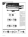
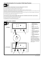
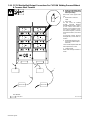
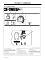
2-11. Weld Output Terminals
Ref. ST-801 627-A
Y Read and understand safety
information in Section 2-10
before proceeding.
1 Positive (+) Weld Output
Terminal
2 Negative (−) Weld Output
Terminal
3 Positive (+) High Inductance
Weld Output Terminal For CC
SMAW And GTAW Welding
Processes
4 Positive (+) Low Inductance
Weld Output Terminal For The
CV FCAW Welding Process
5 Negative (−) Weld Output
Terminal
6 Weld Output Terminal Cover
(Typical For All Weld Output
Terminals)
Cover all weld output terminals with
weld output terminal covers.
Go to Section 2-12 and/or 2-13 for
standard module weld output con-
nections, or Section 2-14 and/or
2-15 for parallel module weld output
connections. Go to Section 2-16
and/or 2-17 for CV FCAW weld out-
put connections.
2
1
6
4
53
CC Module
CC/CV Module

OM-2211 Page 16
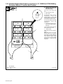
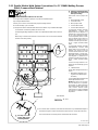
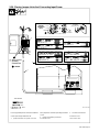
2-12. Standard Module Weld Output Connections For CC SMAW And GTAW Welding
Processes Without A Common Work Terminal
Ref. ST-801 641-A
Y Read and understand safety
information in Section 2-10
before proceeding.
See Section 2-8 for proper cable
size.
1 Electrode Holder Cable
2 Work Cable
For Electrode Positive (Reverse
Polarity/DCEP), connect work
cable to Negative (−) terminal and
electrode holder cable to Positive
(+) terminal (see Section 2-11).
For Electrode Negative (Straight
Polarity/DCEN), reverse cable
connections.
3 Weld Output Terminal Cover
(Typical For All Weld Output
Terminals)
Cover all weld output terminals with
weld output terminal covers.
4 Cable Restraint
Route cables through restraints as
shown.
NOTE:When using a CC/CV mod-
ule (not shown) for CC operation,
use Positive (+) High Inductance
weld output terminal (see Section
2-11). Process Selector switch
(see Section 3-2) must be in SMAW
Hot Start On, or SMAW Hot Start
Off position.
Tools Needed:
3/4, 7/8 in
3
2
1
4
La page est en cours de chargement...
La page est en cours de chargement...
La page est en cours de chargement...
La page est en cours de chargement...
La page est en cours de chargement...
La page est en cours de chargement...
La page est en cours de chargement...
La page est en cours de chargement...
La page est en cours de chargement...
La page est en cours de chargement...
La page est en cours de chargement...
La page est en cours de chargement...
La page est en cours de chargement...
La page est en cours de chargement...
La page est en cours de chargement...
La page est en cours de chargement...
La page est en cours de chargement...
La page est en cours de chargement...
La page est en cours de chargement...
La page est en cours de chargement...
La page est en cours de chargement...
La page est en cours de chargement...
La page est en cours de chargement...
La page est en cours de chargement...
-
 1
1
-
 2
2
-
 3
3
-
 4
4
-
 5
5
-
 6
6
-
 7
7
-
 8
8
-
 9
9
-
 10
10
-
 11
11
-
 12
12
-
 13
13
-
 14
14
-
 15
15
-
 16
16
-
 17
17
-
 18
18
-
 19
19
-
 20
20
-
 21
21
-
 22
22
-
 23
23
-
 24
24
-
 25
25
-
 26
26
-
 27
27
-
 28
28
-
 29
29
-
 30
30
-
 31
31
-
 32
32
-
 33
33
-
 34
34
-
 35
35
-
 36
36
-
 37
37
-
 38
38
-
 39
39
-
 40
40
-
 41
41
-
 42
42
-
 43
43
-
 44
44


Miller KK128916 Le manuel du propriétaire
- Catégorie
- Système de soudage
- Taper
- Le manuel du propriétaire
- Ce manuel convient également à
dans d''autres langues
- English: Miller KK128916 Owner's manual
Documents connexes
-
Miller LC299070 Le manuel du propriétaire
-
-
-
-
-
-
-
-
-