Thermador UCVM36FS Manuel utilisateur
- Catégorie
- Cheminées
- Taper
- Manuel utilisateur
Ce manuel convient également à

MODEL: UCVM30FS / UCVM36FS

2
en
page 03–19
fr
page 20 – 36
es
página 37 – 53

3
WARNING
To reduced the risk of fire, electric shock,
or injury to persons, observe the
following:
A. Installation work and electrical wiring
must be done by qualified person(s) in
accordance with all applicable codes
and standards, including fire-related
construction.
B. Sufficient air is needed for proper
combustion and exhausting of gases
through the flue (chimney) of fuel
burning equipment to prevent back-
drafting. Follow the heating equip-
ment manufacturer’s guideline and
safety standards such as those
published by the National Fired
Protection Association (NFPA), and
the American Society for Heating,
Refrigeration and Air Conditioning
Engineers (ASHRAE), and the local
code authorities.
C. When cutting or drilling into wall or
ceiling, do not damage electrical
wiring and other hidden utilities.
D. Ducted fans must always be vented
to the outdoors.
E. Always unplug or disconnect the
appliance from the power supply
before servicing.
F. This unit is designed for indoor use
only. Use this unit only in the manner
intended by the manufacturer.
WARNING
For general ventilating use only. Do not
use to exhaust hazardous or explosive
materials and vapors.
To reduce risk of fire and to properly
exhaust air, be sure to duct air outside.
Do not vent exhaust air into spaces
within walls, ceilings, attics, crawl spaces
or garages.
To reduced the risk of fire, use only metal
duct work.
To reduce the risk of fire, electric shock
and injury to persons, ventilator
assemblies. All models must be installed
with integral blower, Model
VTN600CV2C or remote blowers models
VTI610D or VTR630D. Other ventilator
blowers cannot be substituted.
To reduce the risk of fire or electric
shock, do not use the fan with any solid-
state speed control device.
This appliance has been found to be in
compliance with UL 507 Standard for
Electric Fans and CAN/CSA-22.2 No.
113 Canadian Standard for Fans and
Ventilators. It is the responsibility of the
owner and the installer to determine if
additional requirements or standard
apply in specific installation.
SAFETY INSTRUCTIONS
READ ALL INSTRUCTIONS BEFORE USING THE APPLIANCE.
READ AND SAVE THESE INSTRUCTIONS
This unit is manufactured for indoor use
only. Do not use this unit outdoors.

4
Parts Needed
❑ Blower (Remote or Integral)
❑ Tape Measure
❑ Phillips Head Screwdriver
❑ Duct Tape
❑ Ductwork (configuration varies
depending on location; See pages 7-12
for further information)
❑ Additional Sheetmetal screws
(as necessary for ductwork installation)
❑ Transition(s) (style varies depending on
ductwork)
Transition box for remote blower
installations is available as an accessory.
❑ Saw (or equivalent for cutting
countertop)
❑ #8 x 1 1/4” Wood Screws (4)
Parts Supplied
❑ Downdraft assembly (1)
❑ #8 Sheetmetal Screws (8)
❑ Blower Cord Strain Relief (1)
❑ Hardware for brackets on vent (2)
❑ Remote Blower Pigtail

5
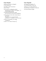
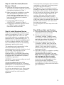
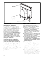
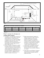
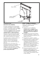
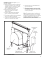
INTRODUCTION
GENERAL DESCRIPTION
The complete downdraft system consits of
the ventilator, the intake and the blower
(See Fig. 1). The blower can be either
integral (mounted on the vent intake in the
cabinet under the cooktop) or a remote
(mounted on the roof or outside wall). When
a remote blower is used, a duct transition is
mounted on the ventilator intake in place of
the integral blower to connect the intake to
the ductwork. The duct transition must be
purchased separately.
The integral blower or duct transition can
be mounted in different positions on the
intake to route ductwork to avoid cabinet,
building framing, utilities, etc.
The downdraft system is available in
30-inch and 36-inch models. It is intended
for use with all brands and models of
residential 30-inch or 36-inch gas or electric
cooktops except professional style
cooktops.
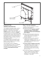
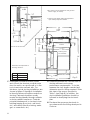
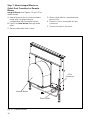
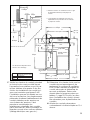
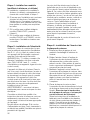
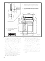
Step 1: Plan the installation
Carefully follow the planning procedures
listed below (See Figure 2).
A. Determine whether a remote or integral
blower will be used. Remote blower
installation requires 4 wires plus a
ground wire to run from the downdraft
to the blower.
B. Make sure that adequate cabinet and
counter space has been provided and
that the intake will be accessible if
service is required.
C. Consider that cross drafts created by
adjacent open windows, doors, air
conditioning, old heating vents, recessed
ceiling lights, and traffic patterns may
affect performance.
D. For gas cooktop installations make sure
that a minimum 10 square inch opening
is provided in the toe-kick or other
cabinet area. Inadequate ventilation of
the cabinet below the cooktop may
result in flame outage when operating
the vent system.
E. Provide for air supply or ”make.up air” to
the room where unit will be installed. If
”make-up air” is not provided, then
problems, such as fireplace chimney
downdrafts, could result.
Strain Relief
Internal Blower
(Not Included)
Top Cap
Fig. 1
Top Cap
Internal blower
(Not Included)
Strain Relief

6
A
B
Integral/Remote
9-13/16"
13"
Cutout
Depth
Cooktop
Cooktop
SB (see
Fig. 7,8)
Drawer
Shelving must
be removable
Be certain to avoid interference with gas and
electric supply to cooktop.
Shelving and drawer depths are dependent
upon cooktop depth and setback.
Dimensions are dependent on
discharge direction.
14"
22"
6 1/2"
5 1/2"
8"
2 1/4"
Fig. 2
F. Investigate potential ductwork routes
and choose the shortest possible route
from the unit to an outside wall or to the
roof via an inside wall and attic. For
duidance, typical ducting installations are
shown in figures 3 through 6. Installation
in island locations will require under floor
ducting. Peninsula locations usually
require ducting laterally through cabinets
or under cabinet toespaces. Consider
potential interferences to ductwork from
building framing (floor joists, wall studs,
etc.) and utilities (electrical wiring, water,
gas, or sewer lines, etc).
G. Determine whether the chosen route of
ducting will meet vent system
performance requirements. To do this,
measure the duct lengths needed and
determine specific fittings required. Enter
this data in the spaces provided in
Table 1 (see Page 8). In addition, the
duct installation guidelines should be
followed in developing the ductwork
plan.
H. Purchase the necessary ductwork in
accordance with the listing developed in
G above.

7
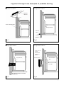
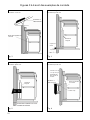
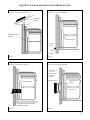
Figures 3 through 6 are examples of possible ducting
Duct Transition Box
Remote
Blower
Fig. 3
Remote Blower
Roof Mount Installation
Integral Blower
12" Min.
Ground
Wall Cap
1255-1
Fig. 4
Integral Blower
Through Wall Installation
Integral Blower
BLOWER ROTATED 90° FOR SIDE
CONNECTION
Fig. 5
Integral Blower
Through Wall Installation
Duct Transition
Box
Remote Blower
10" Collar
3-1/4" x 10" or
8" Duct
End Must Be
Closed and
Sealed
Fig. 6
Remote Blower
Through Wall Installations

8
TOTAL (of both columns)=

9
DUCTWORK INSTALLATION
GUIDELINES
❑ For safety reasons, ducting should vent
directly outdoors (not into an attic,
underneath the house, into the garage or
into any enclosed space).
❑ Keep duct runs as short and straight as
possible.
❑ Duct fittings (elbows and transitions)
reduce air flow efficiency.
❑ Back to back elbows and ”S” turns give
very poor delivery and are not
recommended.
❑ A short straight length of duct at the inlet
of the remote blower gives the best
delivery.
❑ Transition to duct from the integral blo-
wer or remote duct transition as close to
the downdraft as is possible. In order of
preference, use
1st. 10” round duct
2nd. 8” round duct
3rd. 3-1/4” x 14” duct
4th. 7” round duct
5th. 3-1/4” x 10” duct
6th. 6” round duct
❑ The use of flexible metal round duct
should only be used when no other duct
fitting exists. Limit use to short lengths
and do not crush when making corners.
DUCTWORK INSTALLATION
GUIDELINES
❑ Where local codes permit, plastic pipe
(PVC-schedule 40 pipe or ABS pipe 7”
or 8” diameter) can be used in areas of
high ground moisture and in slab floors
to eliminate future rusting.
❑ Use only duct work constructed of
materials that are acceptable by the
applicable codes. All duct should be
26 gauge or heavier to minimize flex due
to air flow.
❑ The remote blowers requires a 10” or 8”
diameter round duct (depending on
model) to match the inlet ring. A
transition is necessyary from other duct
sizes.
❑ Use sheet metal screws as required to
support the duct weight, and seal all
joints with duct tape.
❑ Be certain that the duct work does not
interfere with floor joists or wall studs.
❑ Do not exhaust more than one vent into
a single duct run.
❑ Thermal breaks, such as a short section
of nonmetallic duct, should be used in
areas of extreme cold.
❑ Always use an appropriate roof or
wall-cap with damper. Laundry type wall
caps should never be used.

10
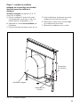
Step 2: Prepare Countertop Cutout
For installation with a Bosch cooktop, refer
to Part A and Figure 7 (Page 12).
For installation with another brand of cook-
top, refer to Part B (Page 13).
For all installations verify that all cutouts will
clear the inside of the front countertop
support rail, and that the cooktop and vent
will be centered left to right within the
cutout. Also, make certain that the front
and rear cutouts are straight and parallel to
the front edge of countertop and the rear
backsplash and/or wall. Assure that the
side cutouts are square to the front and rear
cutouts. All illustrations and dimensions are
based on standard 24” deep by 36” high
American style base cabinets with 25”
countertops.
When installing laminated or solid surface
countertops such as Surell™ and Corian
®
,
be sure to follow the countertop
manufacturer’s instructions regarding
minimum comer radii, reinforcement of
corners, etc.
For overhead cabinet and cooktop side
clearances consult cooktop Installation
Instructions.
A. For installation with a cooktop (Figure 7
and Table 2)
Provide an opening in the countertop as
specified in Table 3 (Page 13). Make sure
that the distance from the front of the
countertop to the front of the cutout is
not less than dimension ”SB”. Verify that
the available flat countertop is
greater than dimensions “OW” by “OD”.
Make certain that the backsplash thickn-
ess does not exceed dimension “BT”.

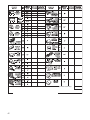
11
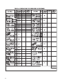
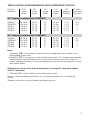
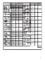
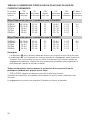
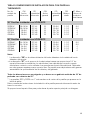
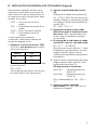
TABLE 2: INSTALLATION DIMENSIONS WITH THERMADOR COOKTOP
Cooktop CW CD OW OD SB BT, Max++
Model No. Cutout Cutout Overall Overall Minimum Backsplash
Width Depth Width Depth Set Back Thickness
30” Cooktops: Installed with UCVM30FS
SGS304* 28-15/16 22-1/4 31 23-3/4 1-1/2 3/4
SGSX304* 28-15/16 22-1/4 31 23-3/4 1-1/2 3/4
CET304 28-3/4 22-1/8 31 23-7/8 2-1/2 0
CEP304 28-3/4 22-1/8 31 23-7/8 2-1/2 0
CEM304 28-3/4 22-1/8 31 23-7/8 2-1/2 0
36” Cooktops: Installed with UCVM36FS
SGS365** 34-15/16 22-1/4 37 23-3/4 1-1/2 3/4
SGSX365** 34-15/16 22-1/4 37 23-3/4 1-1/2 3/4
CET365 34-3/4 22-1/8 37 23-7/8 2-1/2 0
CEP365 34-3/4 22-1/8 37 23-7/8 2-1/2 0
CEM365 34-3/4 22-1/8 37 23-7/8 2-1/2 0
Notes
* Dimension ”SB” is the minimum distance from the leading edge of the counter to the
leading edge of the cutout.
++Dimension ”BT” is the thickness of backsplash that provides 1/4” clearance between vent
and backsplash. Any backsplash with a curved radius where it meets the counter will
require additional clearance. Thicker backsplashes may be used by increasing the counter
and cabinet depths.
All dimensions are in inches and are based upon a standard 24” deep base cabinet
with 25” countertop.
** SGS and SGSX: width in table is at the widest point (center).
Refer to cooktop Installation Instructions for complete information prior to making any
cutouts.
Clearance is provided to allow raising of the hinged main top.

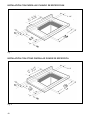
12
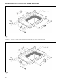
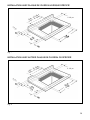
36" : 34 3/8"
30" : 28 3/8"
2 1/4"
INSTALLATION WITH COOKTOPS WHEN SPECIFIED
Fig. 7
INSTALLATION WITH OTHER COOKTOPS WHERE SPECIFIED
2 1/4"
36" : 34 3/8"
30" : 28 3/8"
Fig. 8
CCW
COW
CCD
COD

13
Have the following cooktop measurements
available before proceeding All cooktop
dimensions should be verified through
measurement prior to cutting the
countertop:
CCW = Cooktop Cutout Width
CCD = Cooktop Cutout Depth
COW = Cooktop Oberall Width
COD = Cooktop Oberall Depth
with the above dimensions confirmed,
determine the cutout size as follows:
1. Find the cutout width, (CW):
If CCW is smaller than the cutout width
then:
Width CW
30” 28
3
/
8
36” 34
3
/
8
If CCW is larger than the cutout width
then:
CW = CCW
See Figure 8 for cutout widths and
dimension definations.
2. Calculate the cutout depth, CD:
Determine the cooktop overhang (CO)
CO = (COD-CCD)/2 (Assumes front and
rear cooktop overhangs are equal).
Calculate the cutout depth, (CD):
CD = COD - CO+1-
7
/
8
”
3. Determine setback (SB) distance from
front of countertop to front of cutout.
SB is specified in the installation
instructions shipped with the cooktop.
4. Backsplash thickness must not
exceed BT as calculated below:
BT = 24
7
/
8
” - OD-SB+CO
(Provides
1
/
8
” clearance between vent
and backsplash.) A negative value for BT
means countertop is too small for the
installation.
5. Verify that the available flat countertop
has a width greater than OW and a
depth greater than OD.
OW depends on the installation:
Width 30”: OW equals the greater
of COW or 31”.
Width 36”: OW equals the greater
of COW or 37”.
OD is determined by: OD = COD + 2
1
/
8
”.
6. Cut countertop using dims: CD, CW
and SB as defined in Figure 8.
B. FOR INSTALLATION WITH ANOTHER BRAND OF COOKTOP (Figure 8)

14
Countertop
Surface
Point "P" (Center of Rear Cut-line)
Cabinet Back
Cabinet Bottom Shelf
Left Side
Note: Centerlines of
Rectangular Duct Shown
Plumb line to
intersection A-A
& B-B
Receptacle
Location
Right Side
E
Adjustable
Within Range
Fig. 9
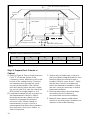
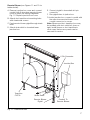
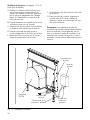
C
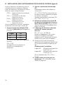
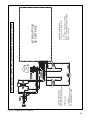
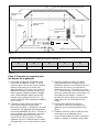
6 3/8” 14 1/2” 1 7/8” 15 1/2” 9 3/4”
DEFG
Cabinet Cutout Dimensions for Blower:
Table 4
Step 3: Prepare Duct Cutouts in
Cabinet
A. Refer to Figure 9. Drop a plumb-line from
Point ”P” at the rear center of the
countertop cutout. Mark this point on the
bottom of the cabinet below. Construct
two reference lines through this point:
one should be parallel to the cabinet
front and directly below the rear counter-
top cutout (Line A-A), and the other (Line
B-B) should be at right angles to A-A.
B. Using these reference lines as a base for
the measurements shown in Table 4,
layout the necessary cabinet cutouts
needed to implement the planned
ductwork route. Where a range of
measurements is noted, choose a
measurement that allows best clearance
from wall studs, floor joists, utilities, or
other obstructions.
Step 3: Prepare Duct Cutouts in
Step 3: Cabinet
C. Temporarily set intake and cooktop in
place and attach integral blower (or duct
transition fitting if a remote blower is
installed). Refer to steps 6 and 7. Verify
that the duct cutouts as marked will
match the hardware installation. Adjust
the duct cutout as necessary to match
hardware installation.
D. Remove temporarily placed hardware
and make cutouts in cabinet to
accommodate ductwork installation.
E. Make all other cabinet modifications
needed to provide proper clearances for
drawers or removable shelving.

15
Step 4: Install Ductwork (Remote
Blower, If Used)
A. Install the ductwork and remote blower
(if used) in accordance with the ductwork
routing plan developed in Step 1.
B. Make sure that the installation complies
with all installations guidelines. Also
check that the opening where duct
passes through outside wall or roof has
been properly flashed and sealed to
prevent leakage.
C. If using Integral Blower, Model
VTN600CV2C, proceed to Step 5.
D. If using Remote Blower Model VTI610D
or VTR630D, refer to Installation
Instructions with that model.
Step 5: Install Electrical Service
Check your local building codes for proper
method of installation. In the U.S., if there
are no applicable local codes, this unit
should be installed in accordance with the
National Electric Code ANSI/NFPA No. 70,
Current Issue. (In Canada, installation must
be in accordance with the CAN 1-B149.1
and .2-Installation Codes for Gas Burning
Appliances and/or lodal codes).
The appliance must be grounded. In the
event of an electrical short circuit,
grounding reduces the risk of electric shock
by providing an escape wire for the
electric current. This appliance is
equipped with a cord having a grounding
wire with a grounding plug. The plug must
be plugged into an outlet that is properly
installed and grounded.
WARNING – Improper grounding can result
in a risk of electric shock.
Consult a qualified electrician if the
grounding instructions are not completely
understood, or if doubt exists as to whether
the appliance is properly grounded.
Do not use an extension cord. If the power
supply cord is too short, have a qualified
electrician install an outlet near the
appliance.
The receptacle should be located under the
countertop so that the 30 inch long power
cord from the vent will reach it.
See Figure 9. The cord should be routed
beneath the appliance and away from heat
generated by the cooktop. Access should
not be obstructed by blower, cabinet work,
ductwork or electrical/gas utilities for the
cooktop. All power for the vent system
(including the remote blower, if used) is
supplied via the cord to the intake unit. The
outlet can usually be extended from another
kitchen outlet or have its own circuit from
the main service panel.
Do not plug vent cord into receptacle until
Step 8.
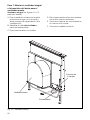
Step 6: Mount Vent and Cooktop
A. Remove grease filters and any packing
materials from inside the intake.
B. Set the vent intake into rear of
countertop opening. Carefully lower it
into position so that the flanges on the
rear sides and edges fully support the
unit hanging from the coluntertop.
C. Hold the unit against the rear of the
countertop opening, and slide the leg
brackets down to meet the bottom of
cabinet. Check and adjust for plumb,
then fasten leg brackets to cabinet with
hardware provided.
D. Place the cooktop in countertop opening
with the rear edge of cooktop
overlapping the front edge of the vent.
Make sure rear edge of cooktop does
not bind against front of snorkel.
Follow the manufacturer’s installation
instructions for installing gasket strips,
protective heat tape (if required),
securing the cooktop to the countertop
and making the cooktop electrical and/or
gas connections.

16
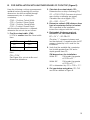
Step 7: Mount Integral Blower or
Outlet Duct Transition for Remote
Blower
Integral Blower (see Figures 10 and 12 for
further detail):
A. Attach blower in front of round exhaust
outlet with 4-6 (depending on
configuration) #8 sheetmetal screws.
B. Feed cord from blower through strain
relief.
C. Secure strain relief with screws.
Step 7: Mount Integral Blower or
Outlet Duct Transition for Remote
Blower
Integral Blower VTN600CV2C (see Figures
10 and 12 for further detail):
D. Attach strain relief to downdraft near
junction box.
E. Connect cord to downdraft at 6 pin
connector.
F. Connect blower to ductwork.
Figure
10
Internal
Blower
Internal Blower
Strain Relief
6 Pin
Connector
Fig. 10 – Internal Blower

17
Remote Blower (see Figures 11 and 12 for
further detail):
A. Remove junction box cover and connect
conduit with 5 wires from remote blower.
Hook up wires per Wiring Diagramm.
Fig. 10. Replace junction box cover.
B. Attach duct transition at mounting holes
with sheetmetal screws.
C. Feed remote blower pigtail through strain
relief.
D. Attach strain relief to downdraft near
junction box.
Integral Blower VTN600CV2C (see Figures
10 and 12 for further detail):
E. Connect pigtail to downdraft at 6 pin
connector.
F. Run pigtail wires to juntion box.
G. Inside junction box, connect conduit with
five wires from remote blower. Use a
conduit connector to secure.
Note: Blower and duct transition box may
be installed with duct outlet left, down or
right. Install blower or duct transition in
such a way that access panels can be
removed for service.
Strain Relief
Junction Box
Conduit To
Remote Blower
g
ure
11
-
R
emo
t
e
Bl
ower
Transition
DHZDHR6
Remote Blower
Pigtail
6 Pin Connector
Fig. 11 – Remote Blower
Transition
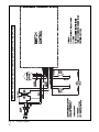
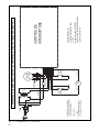
CV2T6

Fig. 12 – Wiring Diagram
18
BLOWER
LOWER
NC
RATING: 120V-10A
ORANGE
GND
60W
GREEN
L1: 120V
WHITE
BROW
DISCONNECT
NC - NORMALLY CLOSED
UPPER
BLOWER
BLOWER
GRAY
C
NO
MOTOR
SWITCH
STEP DOWN
L1
24V
BLACK
POWER
MOTOR
BLACK
LIMIT
CONTROL
ORANGE
LOWERED POSITION
120V
N: GROUNDED WHITE WIRE
YELLOW
TERMINAL
BLUE
LIMIT
NO - NORMALLY OPEN
NC
WARNING: POWER MUST BE DISCONNECTED BEFORE SERVICING THIS APPLIANCE
24V
SWITCH
ABBREVIATIONS:
N
WITH DOWNDRAFT IN
3 WIRE SINGLE PHASE 60Hz
GRAY
LT. BLUE
C
SWITCH
BLACK
SWITCH
C
DC
C - COMMON
60Hz
GND: GROUNDING GREEN WIRE
SWITCH POSITION SHOWN
BLOCK
YELLOW
RED
WARNING: POWER MUST BE DISCONNECTED BEFORE SERVICING THIS APPLIANCE

19
Step 8: Verify Installation, Operation
and Cooktop Alignment
Before performing this procedure, verify that
all packing materials were removed from
inside the snorkel and that the grease filters
and front panel have been properly
installed. Refer to the Care and Use Manual
for instructions regarding filter and front
panel installation.
Plug the vent power cord into a proper
electrical receptacle and ensure that the
circuit is energized.
A. Raise the snorkel to its fully extended
position by pressing the UP / DOWN
push-button once. Do not hold the push-
button. The elevating motor will stop
when the snorkel reaches its full height.
(Note: the blower will not
operate unless
the snorkel is fully raised).
B. Remove protective tape from top cap.
C. Turn the blower ON by selecting in turn
each of the 3 speeds. Let the blower run
several minutes at each speed to
evaluate its operation.
D. With the blower running, lower the
snorkel to its fully retracted position by
pressing the the UP / DOWN push-but-
ton once. The blower will immediately
turn off.
E. With the blower on HIGH, close the
windows and doors to the area to ensure
that fan does not cause back drafting in
any outlet vent for another appliance.
F. Raise and lower the vent again, and
check to make sure that the top cap on
the snorkel does not catch on the back
edge of the cooktop when it is lowered. If
interference occurs, adjust the position
of the cooktop by moving it against the
front edge of the countertop. Failure to
eliminate interference may result in
permanent damage to the vent. Also,
ensure that the vent support legs have
been properly secured to the cabinet
base using the screws provided.
If the vent system does not operate
satisfactorily during any of the above
procedures, review all steps in these
Installation Instructions to ensure that
nothing has been omitted or overlooked.
Also, refer to the Care & Use Manual for
additional information or call Thermador
Customer Support 1-800-735-4328.

20
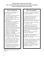
AVERTISSEMENT
Pour réduire le risque d’incendie, de
choc électrique ou de blessures,
observer ce qui suit:
A. L’installation et le câblage électrrique
doivent être effectués par des
personnes qualifiées conformément à
toutes les normes et codes
applicables, incluant la construction
relative au feu.
B. Siffisamment d’air est nécessaire pour
une combustion appropriée et
l’echappement des gaz par tirage
(cheminée) d’équipement à
combustion pour évier le tirage
arrière. Suivre les directives du
fabricant d’équipement de chauffage
et les normes de sécurité telles celles
fournies par l’Association de
pretection des incendies nationale
(NFPA) et la Société américaine
d’ingénierie de chauffage,
réfrigération et climatisation (ASHRAE)
ainsi que les codes locaux.
C. Au moment de couper ou percer un
mur ou plafond, ne pas endommager
le câblage électriques et autres.
D. Les ventilateurs à conduit doivent
toujours être ventilés vers l’extérieur.
E. Avant toute intervention, pensez à
toujours débrancher l'appareil du
réseau d'alimentation électrique.
F. Cet appareil est conçu pour une
utilisation intérieure seulement. Utiliser
cet appareil de la façon à laquelle il
est destiné par le fabricant.
AVERTISSEMENT
Pour ventilation générale seulement. Ne
pas ventiler des vapeurs ou matériaux
explosifs ou hasardeux.
Pour réduire le risque d’incendie et pour
un échappement d’air approprié,
s’assurer d’acheminer l’air vers
l’extérieur. Ne pas ventiler l’air
d’échappement dans les murs, plafonds,
greniers, espaces fermés ou garages.
Pour réduire le risque d’incendie, utiliser
des conduits en métal.
Pour réduire le risque d’incendie, de
choc électrique et de blessures, les
assemblages de ventilatuer pour les
modèles doivent être installés avec une
soufflerie intégrée, modèle VTN600CV2C
ou modèles VTI610D ou VTR630D à
télécommande.
D’autres souffleries de ventilateur ne
peuvent être substituées.
Pour réduire le risque d’incendie ou de
choc élecrique, ne pas utiliser le
ventilateur avec dispositif de contrôle de
vitesse à semi-conducteur.
Cet appareil est conforme avec la norme
UL 507 pour ventilateurs électriques et la
norme canadienne CAN/CSA-22-2
n° 113 pour ventilateurs. Il incombe au
propriétaire et à l’installateur de
déterminer si des normes ou exigences
additionnelles s’appliquent pour une
installation spécifique.
INSTRUCTIONS DE SÉCURITÉ
LIRE TOUTES LES INSTRUCTIONS AVANT D’UTILISER L’APPAREIL.
LIRE ET CONSERVER CES INSTRUCTIONS
Cet appareil est fabriqué pour une utilisation
intérieure seulement. Ne pas utiliser pour
l’extérieur.
La page est en cours de chargement...
La page est en cours de chargement...
La page est en cours de chargement...
La page est en cours de chargement...
La page est en cours de chargement...
La page est en cours de chargement...
La page est en cours de chargement...
La page est en cours de chargement...
La page est en cours de chargement...
La page est en cours de chargement...
La page est en cours de chargement...
La page est en cours de chargement...
La page est en cours de chargement...
La page est en cours de chargement...
La page est en cours de chargement...
La page est en cours de chargement...
La page est en cours de chargement...
La page est en cours de chargement...
La page est en cours de chargement...
La page est en cours de chargement...
La page est en cours de chargement...
La page est en cours de chargement...
La page est en cours de chargement...
La page est en cours de chargement...
La page est en cours de chargement...
La page est en cours de chargement...
La page est en cours de chargement...
La page est en cours de chargement...
La page est en cours de chargement...
La page est en cours de chargement...
La page est en cours de chargement...
La page est en cours de chargement...
La page est en cours de chargement...
La page est en cours de chargement...
La page est en cours de chargement...
La page est en cours de chargement...
-
 1
1
-
 2
2
-
 3
3
-
 4
4
-
 5
5
-
 6
6
-
 7
7
-
 8
8
-
 9
9
-
 10
10
-
 11
11
-
 12
12
-
 13
13
-
 14
14
-
 15
15
-
 16
16
-
 17
17
-
 18
18
-
 19
19
-
 20
20
-
 21
21
-
 22
22
-
 23
23
-
 24
24
-
 25
25
-
 26
26
-
 27
27
-
 28
28
-
 29
29
-
 30
30
-
 31
31
-
 32
32
-
 33
33
-
 34
34
-
 35
35
-
 36
36
-
 37
37
-
 38
38
-
 39
39
-
 40
40
-
 41
41
-
 42
42
-
 43
43
-
 44
44
-
 45
45
-
 46
46
-
 47
47
-
 48
48
-
 49
49
-
 50
50
-
 51
51
-
 52
52
-
 53
53
-
 54
54
-
 55
55
-
 56
56


Thermador UCVM36FS Manuel utilisateur
- Catégorie
- Cheminées
- Taper
- Manuel utilisateur
- Ce manuel convient également à
dans d''autres langues
- English: Thermador UCVM36FS User manual
- español: Thermador UCVM36FS Manual de usuario