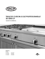
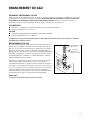
DCS BGC-3036 Manuel utilisateur
- Catégorie
- Barbecues
- Taper
- Manuel utilisateur

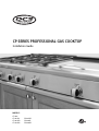
CP SERIES PROFESSIONAL GAS COOKTOP
Installation Guide
MODELS:
CP-366
CP-364GL
CP-364GD
CP-484GG
CP-485GD
CP-486GL
CP-486GD


A MESSAGE TO OUR CUSTOMERS
1
Thank you for selecting this DCS professional Cooktop. Because of this appliance’s unique features we have
developed this Installation Guide. It contains valuable information on how to properly install your new appliance
for years of safe and enjoyable cooking.
F
or your convenience, product questions can be answered by a DCS Customer Care Representative
by phone: 1-888-281-5698, email: [email protected],
or by mail:
Fisher & Paykel Appliances, Inc.
Attention: DCS Customer Care
5900 Skylab Road
Huntington Beach, CA 92647 www.dcsappliances.com
WARNING
Improper installation, adjustment alteration, service or maintenance can cause property damage, injury or death.
Read the installation, operating and maintenance instructions thoroughly before use, installing or servicing this
equipment.
WARNING
If the information in this manual is not followed exactly, a fire or explosion may result causing property damage,
personal injury or death.
Do not store or use gasoline or other flammable vapors and liquids in the vicinity of this or any other appliance.
DANGER
I
f You Smell Gas:
1. Do not try to light any appliance.
2. Do not touch any electrical switch; do not use any phone in your building.
3.
Immediately call your gas supplier from a neighbor’s phone. Follow the gas supplier’s instructions.
4. If you cannot reach your gas supplier, call the fire department.
5. Installation and service must be performed by a qualified installer, service agency or the gas supplier.
WARNING
T
o r
educ
e the risk of injur
y t
o persons in the event of a cooktop grease fire, observe the following: Turn burner off
first
. Smother flames with a close
-fitting lid
, c
ook
ie sheet
, metal tr
a
y
, baking soda or use a dry chemical or foam-type
fir
e extinguisher. Be careful to prevent burns. If the flames do not go out immediately evacuate and call the fire
depar
tmen
t
. Nev
er pick up a flaming pan -
You may be burned. DO NOT USE WATER ON GREASE FIRES, including
w
et dishcloths or t
o
w
els - a violen
t st
eam e
xplosion will r
esult
. Use an extinguisher ONLY if:
1. You know you have a Class ABC extinguisher, and you already know how to operate it.
2. The fire is small and contained in the area where it started.
3. The fire department is being called.
4. You can fight the fire with your back to an exit.
PLEASE RETAIN THIS MANUAL FOR FUTURE REFERENCE.
NOTE: Please write the Model and Serial Number on this page for references (located on the rating plate behind
the unit right side)
MODEL NUMBER
SERIAL NUMBER

2
TABLE OF CONTENTS
INTRODUCTION 3
SAFETY PRACTICES AND PRECAUTIONS 4-6
MODELS 7
PLANNING THE INSTALLATION 8-9
UNPACKING AND HANDLING 9-10
VENTILATION REQUIREMENTS 11
CABINET PREPARATION 12-14
BACKGUARD INSTALLATION 15
ELECTRICAL CONNECTIONS 15
GAS HOOK-UP 16
TEST AND ADJUSTMENTS 17
CLEANING EXTERIOR SURFACES 18
INSTALLER FINAL CHECKLIST 19
HOW TO OBTAIN SERVICE 20
WARRANTY 21-22

3
INTRODUCTION
The DCS Professional CP Cooktops feature a large number of features varying with each model. All models
f
eature a minimum of 4 surface burners, with the option of up to 6 surface burners on all models. All of the 48"
and 36" Cooktops feature the possibility of various grill and griddle combinations. All cooktop models require
t
he installation of one of the two offered backguards, if installed with less than 12” of clearance to combustible
material. See page 14.
IMPORTANT INSTALLATION INFORMATION
The cooktops are tested in accordance with ANSI Z21.1 Standard for Household Cooking Gas Appliances. These
cooktops must be installed in conjunction with a suitable overhead vent hood. (See ventilation requirements).
Due to the professional high heat capacity of this unit, particular attention should be paid to the hood and duct
work installation to ensure it meets local building codes. To eliminate risk of burns or fire by reaching over
heated surface units, cabinet storage located above the surface units should be avoided.
Check local building codes for the proper method of cooktop installation. Local codes vary. Installation,
electrical connections, and grounding must comply with all applicable codes. In the absence of local codes, the
cooktop should be installed accordance with the National Fuel Gas Code ANSI Z223.1 and National Electrical
Code ANSI / NFPA 70. Be sure that the unit being installed is set up for the kind of gas being used. The gas
cooktop is shipped from the factory set and adjusted for natural gas or LP (propane), depending on the specific
model ordered.
Verify that the cooktop is compatible with gas supply at the installation site before
proceeding further. Return cooktop to dealer if unit is not set for site gas supply.

4
SAFETY PRACTICES AND PRECAUTIONS
When properly cared for, your new DCS Appliance has been designed to be a safe, reliable cooking appliance.
When using this restaurant caliber appliance, use it with extreme care, as this type appliance provides intense
heat and can increase the accident potential. Basic safety precautions must be followed when using kitchen
a
ppliances, including the following:
■
R
ead the Use and Care Manual, which came with this appliance, thoroughly before using your new appliance.
This will help to reduce the risk of fire, electric shock, or injury to persons.
■
Begin by insuring proper installation and servicing. Follow the installation instructions in this manual. Be sure to
have a qualified technician install and ground this appliance before using.
■
Have the installer show you where the gas supply shut-off valve is located so you will know how and where to
turn off the gas to the appliance.
■
If you smell gas, the installer has not done a proper job of checking for leaks. You can have a small leak and
therefore a faint gas smell if the connections are not completely tight. Finding a gas leak is not a “do-it-yourself”
procedure. Some leaks can only be found with the burner control in the ON position and for your protection it
must be done by a qualified service technician.
■
If by some chance a burner goes out and gas escapes, open a window or a door to let the room air out. Do not
attempt to use the appliance until the gas has had time to dissipate. Follow the instructions on page 1, “For
your safety – if you smell gas”.
■
This appliance has been factory assembled for natural or LP gas. It should be correctly adjusted from the factory
for the type of gas that is used.
■
Do not repair or replace any part of this appliance unless it is specifically recommended in this manual. All other
servicing should be referred to a qualified technician.
■
Children should not be left alone or unattended in an area where appliances are in use. They should never be
allowed to turn knobs, push buttons, sit or stand on any part of an appliance while in operation.
WARNING:
Do not store items of interest to children above or at the back of any appliance. Children could be seriously injured
if they should climb onto the appliance to reach these items.
■
Never store anything on the cooktop. Flammable materials can catch fire, plastic items may melt or ignite and
other types of items could be ruined.
■
Do not hang articles from any part of the appliance or place anything against the oven. Some fabrics are quite
flammable and may catch on fire.
■
If the appliance is near a window be certain the curtains do not blow over or near the cooktop burners; they
could catch on fire.
■
Do not use water on grease fires. Turn all burners OFF, then smother fire with baking soda or use a dry chemical
or foam-type fire extinguisher.
■
Never let clothing, pot holders, or other flammable materials come in contact with, or too close to, any burner or
burner grate until it has cooled. Fabric may ignite and result in personal injury.
■
Be certain to use only dry pot holders: moist or damp pot holders on hot surfaces may cause burns from steam.
Do not use a towel or other bulky cloth in place of pot holders. Do not let pot holders touch hot burners, or
burner grates.
■
For personal safety, wear proper apparel. Loose fitting garments or hanging sleeves should never be worn while
using this appliance. Some synthetic fabrics are highly flammable and should not be worn while cooking.

5
SAFETY PRACTICES AND PRECAUTIONS
■ Do not use aluminum foil to line any part of the cooktop. Doing so, heat will be trapped underneath it. This
t
rapped heat can upset the cooking performance and can damage the finish of the cooktop parts.
■ This appliance is for cooking. Never use the cooktop to warm or heat a room. This could damage the cooktop.
■
When using the cooktop: Do not touch the burner grates or the immediate surrounding area. Areas adjacent to
the burners may become hot enough to cause burns.
■
Never leave the cooktop unattended when using high flame settings. When cooking with high flame settings,
boil overs may cause smoking and greasy spill overs may ignite. More importantly, if the burner flames are
smothered by a severe boil over which effects the igniter, unburned gas will escape into the room.
■
Only certain types of glass, heat-proof glass-ceramic, ceramic, earthen ware, or other glazes utensils are suitable
for cooktop use. This type of utensil may break with sudden temperature changes. Use only on low or medium
flames settings according to the manufacturer’s directions. The use of professional utensils is recommended.
■
Do not heat unopened food containers; a build up of pressure may cause the container to burst.
■
During cooking, set the burner control so that the flame heats only the bottom of the pan and does not extend
beyond the bottom of the pan. This could heat and/or melt the handles, and may increase cooking time.
■
Always use utensils that have flat bottoms large enough to cover the burner. The use of undersized utensils will
expose a portion of the flame to direct contact and may result in ignition of clothing.
■
To minimize burns, ignition of flammable materials and unintentional spill overs, position handles of utensils
inward so they do not extend over adjacent work areas, cooking areas, or the edge of the cooktop.
■
Hold the handle of the pan to prevent movement of the utensil when stirring or turning food.
■
Grease is flammable. Let hot grease cool before attempting to handle it. Avoid letting grease deposits collect
around the cooktop burners. Clean after each use or boil over.
■
For proper lighting and performance of the cooktop burners, keep the burner ports clean. It may be necessary to
clean these when there is a boil over or when the burner does not light, even though the electronic igniters
click.
■
Do not use the grill for cooking excessively fatty meats or products which promote flare-ups. Do not use
cooking utensils on the grill.
WARNING! NEVER use this appliance as a space heater to heat or warm the room.
Doing so may result in carbon monoxide poisoning.

6
SAFETY PRACTICES AND PRECAUTIONS
■
Clean the cooktop with caution. Avoid steam burns; do not use a wet sponge or cloth to clean the cooktop
while it is hot. Some cleaners produce noxious fumes if applied to a hot surface. Follow directions provided by
the cleaner manufacturer.
■
Be sure all the cooktop controls are turned off and the appliance is cool before using any type of aerosol cleaner
on or around the appliance. The chemical that produces the spraying action could, in the presence of heat,
ignite or cause metal parts to corrode.
■
Clean the ventilator hood and filters above the cooktop frequently so grease from cooking vapors does not
accumulate on them.
■
Turn the ventilator OFF in case of fire or when intentionally “flaming” liquor or other spirits on the cooktop. The
blower, if in operation, could unsafely spread the flames.
■
DO NOT obstruct the flow of combustion or ventilation air to the appliance. Be sure a fresh air supply is
available.
■
For safety reasons and to avoid damage to the appliance never sit, stand, or lean on the cooking surface.
■
Service should only be done by authorized technicians. Technicians must disconnect the power supply before
servicing this appliance.
WARNING:
California Proposition 65 - The burning of gas cooking fuel generates some by-products which are known by the
State of California to cause cancer or reproductive harm. California law requires businesses to warn customers of
potential exposure to such substances. To minimize exposure to these substances, always operate this unit
according to the instructions contained in this booklet and provide good ventilation to the room when cooking with
gas.
RECOMMENDATIONS ON HOOK-UP TO GAS SUPPLY:
A manual valve must be installed external to the appliance, in an accessible location from the front for the
purpose of shutting off the gas supply. The supply line must not protrude beyond the back of the unit. Make
sure the gas supply is turned off at the wall valve before connecting the appliance.
The gas supply connections should be made by a qualified technician and in accordance with local codes or
ordinances. In the absence of a local code, the installation must conform to the latest edition of National Fuel
Gas Code ANSI Z223.1.
NOTE:
This pro
duct m
ust b
e installed b
y a lic
ensed plumber or gas fitter when installed within the Commonwealth of
Massachusetts.
NOTE:
(mandatory for the State of Massachusetts)
Alternate method of supplying gas must be installed
into the unit.
Installer supplied shut-off valve
must be easily accessible inside
cabinetry.
Gas Supply

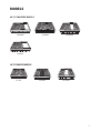
MODELS
7
48” CP COOKTOP MODELS
CP-484GG
36” CP COOKTOP MODELS
CP-366
CP-486GL CP-486GD
CP-485GD
CP-364GL CP-364GD

8
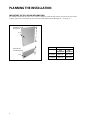
PLANNING THE INSTALLATION
IMPORTANT INSTALLATION INFORMATION
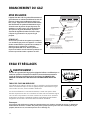
A
ll cooktop models with less than a 12” clearance between combustable material and the back edge of the
cooktop, require the installation of one of the two offered Wall Mount Backguards – see page 15.
FIG. 1
30”
12”
Wall Mount Full
Backguard
Wall Mount
Low Backguard
15/16”
15/16”
Model Number
Low
Back
guard
Full
Back
guard
48” Cooktop BGC-1248 BGC-3048
36” Cooktop BGC-1236 BGC-3036

9
PLANNING THE INSTALLATION
RECOMMENDED INSTALLATION INSTRUCTION
Install components in the following order:
A. Vent Hood
B. Backguard System (sold separately)
C
. Cooktop
1. Locate cooktop according to cooktop installation instructions.
2. Measure distance from counter surface to top of trim on cooktop adding 1/8” for backguard clearance.
3. Transfer this measurement to the wall. This will mark the bottom of your backguard.
4. From this line measure 30-1/16” up wall to mark top of 30” backguard. This is the minimum height that the
bottom of your vent hood can be installed.
5. Follow vent hood manufacturer’s installation instructions to install vent hood.
6. Follow backguard installation instructions to install backguard.
7. Connect gas and electric connections and slide cooktop into position.
NOTE:
A manual gas supply valve must be installed. See page 16.
CAUTION:
Proper equipment and adequate manpower must be used in moving the cooktop to avoid personal injury or
damage t
o the unit.
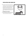
MOVING AND PLACING THE COOKTOP
The cooktops have a shipping weight of approximately 228 pounds (36" models) and 324 pounds (48" models).
After removal of packing materials, it is recommended that the grates and drip pan (below knobs) be removed to
facilitate handling. This will reduce the weight to about 150 pounds.
■
DO NOT REMOVE THE GRILL OR GRIDDLE ASSEMBLIES.
NOTE:
If a solid side cabinet wall exists on one or both sides, you will need to notch the front corner of the cabinet to match the
c
ounter top notch and to provide clearance for the cooktop front (see page 14).
It may be necessary to remove the cooktop knobs to pass through some doorways. With the knobs removed a
29-3/8" wide opening is required. Remove the outer carton and packing material from the shipping base. The
cooktop is held to the skid by four straps. After removing the straps, the cooktop must be lifted and removed
from the skid.
UNPACKING AND HANDLING

10
UNPACKING AND HANDLING
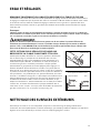
■
The professional cooktop should be moved close to
its final location. Electric and gas connections should
be made (pgs. 15 & 16) and the backguard installed
(
as required, pg. 8 & 15) before the cooktop is placed
in its final position. The grill and griddle sections are
f
astened in place at the front with screws. They are
designed to be stationary and not meant to be
removed for cleaning. The griddle has two leveling
screws beneath the rear flue cover which can be used
to adjust the griddle to the desired slope. The center
screw is for shipping and should be removed. See
Fig. 2.
ANCHORING THE COOKTOP
■
Due to the weight of the cooktop, along with a built-
in side frame gasket that is meant to rest and create
a seal on the counter top once installed, it is not
necessary to anchor the unit to the counter.
Fig. 2
Shipping Screw
(remove)
Outer Leveling
Screws (2)
Griddle Flue Cover

11
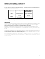
VENTILATION REQUIREMENTS
A suitable exhaust hood must be installed above the range. The following chart indicates the minimum blower
capacity recommended for hood ventilation.
* When installing a unit featuring a grill, GL models, requires a 1200 CFM ventilation unit.
CAUTION:
Ventilation hoods and blowers are designed for use with single wall ducting. However, some local building codes or
inspectors may require double wall ducting and/or damper. Consult local building codes and/or local agencies,
before starting, to ensure that hood and duct installation will meet local requirements.
Hood blower speeds should be variable to reduce noise and loss of heated or air conditioned household air
when maximum ventilation is not required. Normally, the maximum blower speed is only required when using
the grill.
For best smoke elimination, the lower edge of the hood should be installed a minimum of 30" to a maximum of
36" above the cooktop cooking surface, (page 12). If the hood contains any combustible materials (i.e. a wood
covering) it must be a minimum of 36" above the cooking surface.
Due to a high volume of ventilation air, a source of make-up air (outside replacement air) is recommended. This
is particularly important for tightly sealed and insulated homes. A reputable heating and ventilating contractor
should be consulted.
Ventilation Unit
Standard Counter
Installation
Recommendatons
Island Installation
Recommendatons
HOOD 24" Deep x Unit Width 30" Deep x 36" at Bottom
BLOWER
48” Cooktop
1200 CFM
1200 CFM
*36” Cooktop
600-1200 CFM
600-1200 CFM

12
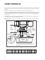
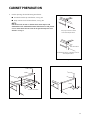
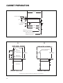
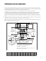
CABINET PREPARATION
1
. To ensure professional results, the cabinet and countertop openings should be prepared by a qualified cabinet
worker. We recommend having the cooktop available before cutting the opening for more precise dimension
v
erification.
2. The clearances shown in Fig. 8 pg. 14 are required for all types of backguard installations.
3. The cooktop is designed to hang from the countertop from its rear and side flanges. The countertop, however,
must be strong enough to support this heavy cooktop. It may be necessary to add a supporting cleat along each
side or another form of support such as a 2” x 4” corner brace on each side, or a deck to set the cooktop on.
See Fig. 3 & 5.
4. The cooktop can be installed in various positions with the front either flush or projecting, depending on the
countertop depth. See Fig. 4 & Fig. 7 (cooktop side view).
5. Establish the centerline of the desired cooktop location. It should be the same as the center of the overhead
ventilation hood.
G
H
F
D
E
Min. 48" Wide Hood
Min. 36" Wide Hood
J
16"
Electrical and
Gas Supply.
2"
13"
Max.
12" Min. to
Combustible
Material#,
Each Side
CAUTION
36" Min. to
combustible
material#, from
cooking surface
Cooking Surface
2" x 4" corner
support (if required)
18" Min.
A
C
B
# As defined in the “National Fuel Gas Code” (ANSI Z223.1, lastest edition).
The horizontal surfaces of the cooktop trim must not be below
countertop level.
30" Min.
36" Max.
for best smoke
elimination
Fig. 3
M
odels ABCDEFGHJ
CP-48 Models 47-7/8” 26-1/2” 8-7/16” 46-5/16” 22-3/4” 8” 7/8” 0 ~ 2-1/2” 17”
CP-36 Models 35-7/8” 26-1/2 ” 8-7/16 ” 34-15/16” 22-3/4” 8” 1/2” 0 ~ 2-1/2” 7”

CABINET PREPARATION
13
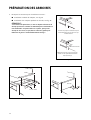
6. Cut the openings for the following installation:
■ Standard counter top installation, see Fig. 8A
■ Deep counter or island installation, see Fig. 8B
NOTE:
If the deck is used, the sides or bottom of the cutout may be solid
combustible or non-combustible material. If the bottom is solid, provide
a 6" x 6" cutout in the left rear corner for the gas inlet and power cord
clearance. See Fig. 6.
Flush with cabinets
Front projects outward as shown
from standard depth cabinet.
Front flush with cabinets; a minimum
of 25
3/4" cabinet depth required
Fig. 4
Front flush with cabinets; a minimum of 25-3/4”
cabinet depth required
Front projects outward as shown
from standard depth cabinet.
Flush with cabinets
Counter-Sunk Screws
Fig. 5
Counter-Sunk Screws
Fig. 6
6
6
Cutout

CABINET PREPARATION
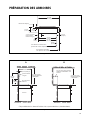
14
8-7/16"
2
2-3/4"
26-1/2"
23-1/4"
3" To Center Line
of Gas Inlet
1/2"
1/2"
5/8"
Cabinet face for installation
with projecting control panel
Cabinet face for installation
with flush control panel
2-1/2"
C
ountertop level
#
Fig. 7
30"
26-1/2"
12" Min. to Combustibles
#
without Backguard
15/16"
12"
Wall Mount
Low Backguard
Base Cabinet
Wall Mount
Full Backguard
36” Min. to
Combustibles
#
36” Min. to
Combustibles
#
#
As defined in the “National Fuel Gas Code” (ANSI Z223.1, lastest edition).
Fig. 8
A B

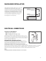
ELECTRICAL CONNECTIONS
15
ELECTRICAL REQUIREMENTS
■
120 VAC, 60 Hz., single phase
■
CP-48: 15 Amp. Max. (use 15 Amp. circuit)
■
CP-36: 15 Amp. Max. (use 15 Amp. circuit)
Always disconnect electric supply cord from the wall outlet or service
disconnect before servicing this appliance. Observe all governing codes
and ordinances when grounding, in absence of which, observe National
Electrical Code ANSI / NFPA No. 70.
RECOMMENDED GROUNDING METHOD
This appliance is factory equipped with a power supply cord with a
three-prong grounding plug (with polarized parallel blades). It must be
plugged into a mating grounding type receptacle, connected to a
correctly polarized 120 Volt circuit. If the circuit does not have a
grounding type receptacle, it is the responsibility and obligation of the
installer to have the existing receptacle changed to a properly grounded and polarized receptacle in accordance
with all applicable local codes and ordinances by a qualified electrician. In the absence of local codes and
ordinances, the receptacle replacement shall be in accordance with the National Electrical Code.
Note:
The third prong should not, under ANY circumstances, be cut or removed.
Receptacle Box
Cover Plate
Three Prong
Receptacle
Three
Prong
Plug
Fig. 10
Fig. 9
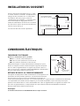
BACKGUARD INSTALLATION
T
he backguard is located as shown in Fig. 9. Secure the
backguard to the wall behind the range. Specific
instructions for installation of the full backguard or low
backguard can be found packaged with the backguard.
See also page 8, “Planning The Installation” section. A
b
ackguard must be installed when there is less than a
12” clearance between combustibles and the back of
the range (above the cooking surface). See fig. 8.
DCS backguards are sold separately.
12"
30"
15/16"
Wall Mount
Full Backguard
(
Model #’s BGC-3036, BGC-3048)
Wall Mount
Low Backguard
(
Model #’s BGC-1236, BGC-1248)

16
GAS REQUIREMENTS
Verify the type of gas supplied to the location. The cooktop is shipped from the factory set up and adjusted for
Natural Gas or LP (propane), depending on the specific model ordered.
Verify that the cooktop is compatible
with gas supply at the installation site before proceeding further.
Return the cooktop to the dealer if the unit is
not set for the gas supplied at the site.
NATURAL GAS
■ Connection: 1/2” NPT Minimum 5/8” dia. flex line. ■ Supply Pressure: 6” to 14” W.C.
LP GAS
■ Connection: 1/2” NPT Minimum 5/8 dia. flex line. ■ Supply Pressure: 11” to 14” W.C.
A regulator is required at the LP source to provide a maximum of 14” W.C. to the cooktop regulator.
HOOK-UP TO GAS SUPPLY
A manual valve must be installed external to the appliance, in an
accessible location from the front for the purpose of shutting off the
gas supply (Fig. 11). Make sure the gas supply is turned off at the
wall valve before connecting the appliance. The gas supply
connections should be made by a qualified technician and in
accordance with local codes or ordinances. In the absence of a local
code, the installation must conform to the latest edition of National
Fuel Gas Code ANSI Z223.1.
To prepare the unit for connection to the gas supply, thread the
supplied 1/2” pipe nipple into the elbow on the end of the manifold.
The elbow is located inside the chassis of the unit, on the end of the
manifold, facing down. See fig.12. It is accessible through the
square cutout in the left rear corner of the chassis bottom. Connect
the outlet of the regulator to the exposed end of the nipple, connect
the flex line from the gas supply to the inlet side of the regulator.
NOTE:
Pipe seals must be used on all pipe threads.
CAUTION:
T
he appliance must be isolated from the building’s gas
supply piping system by closing its individual manual
shut-off valve during any pressure testing of the gas
supply piping sy
stem at test pressures equal to or less
than 1/2 psig (3.5kPa.). The appliance and its
individual shut-off valve must be disconnected from
the gas supply piping sy
stem during any pressure
testing of the system at the test pressures in excess of
1/2 psig (3.5kPa.). When checking the manifold gas
pressure, the inlet pressure to the regulator should be
at least 7.0”W.C. for natural gas or 12.0” for LP.
NOTE:
The arrow on the regulator indicating direction of gas
flow should be pointing towards the unit. The flex line
for the gas supply must be metal and be approved by an
approved certif
ying agenc
y (
A
GA, CGA, or UL). Never use
a hose made of rubb
er or other synthetic material, as the
heat may cause the hose t
o melt and dev
elop leaks
.
GAS HOOK-UP
Fig. 12
*Installation must conform with
local codes or with the National
Fuel Gas Code ANSI Z223.1 or
the CAN/CGA-B149.2 Propane
Installation Code
Coupling
1/2 NPT black
1/2 NPT
Close Nipple
Regulator
LP/NG (included)
Adapter 1/2 NPT
to 3/8 flare fitting
Do not put threading
compound on these
threads
Bottom of unit
Threading compound
must be resistant to LP gas
1/2 x 5" NPT
Close
Nipple
Installer supplied shut-off
valve must be easily
accessible*
Fig. 11
Flex Line to Cooktop
Manual Shut-Off
Valve must be
Easily Accessible
!

17
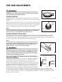
TEST AND ADJUSTMENTS
WARNING:
F
or warranty coverage, DCS requires that burner adjustments be made by a
qualified technician at the time of installation. Extreme care should be used
when adjustments are made after installation.
COOKTOP BURNERS
The cooktop burners are not adjustable. Proper operation is achieved when
the correct orifices for gas supply are installed at the factory, based on model
ordered.
When installing the burner port ring, be sure that the two locating pins in the
bottom side of the brass port ring are properly aligned with the locating notch
and center holes on the top side of the simmer ring. Incorrect alignment will
produce a potentially dangerous flame and poor burner performance.
Note:
No air shutter adjustment is possible on the cooktop burners. Burner flames should
be blue and stable with no yellow-tipping (some yellow-tipping is normal with LP
gas), excessive noise, or lifting of flame from the burner (Fig. 13).
COOKTOP BURNER LIGHTING NOTE
The cooktop burners have an infinite number of heat settings and there are no fixed positions on the control
knobs between HI and LO. To turn the cooktop burner on, push in on the control knob and turn it counter-
clockwise to the “LITE” position. An audible clicking sound will be heard. When the gas has been ignited by the
electronic spark igniter, turn the knob to the desired setting (Fig. 14).
Note:
The igniter will continue to click until a flame is present. If the cooktop burner
does not ignite, check the spark igniter by listening for a clicking sound. If you
do not hear the igniter click, turn off the burner. Check for a tripped circuit
breaker, blown fuse, or poor wire connection to the igniter.
WARNING:
When turning on any cooktop burner, be sure to stop at the “LITE” position
bef
or
e turning the burner t
o a flame setting f
or cooking. If the burner is not
lit and it is turned beyond the “LITE” position, to HI, MEDIUM, or LO, there
will be a burst of flame when the burner does ligh
t
. This could cause burns
or damage t
o the surr
ounding c
oun
t
er
top.
THIS ADJUSTMENT SECTION APPLIES TO THE GRIDDLE
AND GRILL BURNERS.
Check for the proper burner flame characteristics and adjust air shutters if
necessary (fig. 15). Each valve and air shutter is individually tested and
adjusted prior to shipment. Normally adjustment is not required,
however, vibration during transit, gas conversion or variations in the local
gas supply may make minor adjustments necessary. Burner flames should
be blue and stable with no yellow tips, excessive noise or lifting of the
flame from the burner. If any of these conditions exist, check that the air
shutter or burner ports are not blocked. If this condition persists, adjust
the air shutter as required. If the flame is too yellow, indicating insufficient air, adjust the shutter counter-
clockwise to increase air inlet. If the flame is noisy or tends to lift away from the burner, indicating too much
air, turn the shutter clockwise to reduce air. The griddle flames should be 1-1/2" to 2". The grill burner flames
should be 3/8” to 5/8” (fig. 16).
1-1/2"
COOKTOP BURNER
FIG. 13
FIG. 14
SIM
LO
LITE
HI
OFF
Fig. 15
1-1/2" ~ 2"
Typical Section of Proper Flame
3/8" ~ 5/8"
(Grill)
(Griddle)
Fig. 16
Typical Section of Proper Flame
Griddle
1-1/2” – 2”
3/8” – 5/8”
Grill
air shutter

18
CLEANING EXTERIOR SURFACES
The stainless steel surfaces may be cleaned by wiping with a damp soapy cloth or sponge. Any liquid soap (like
Dawn or Stainless Steel Magic) will remove fingerprints and smears. Do not use steel wool as it will scratch this
surface.
La page est en cours de chargement...
La page est en cours de chargement...
La page est en cours de chargement...
La page est en cours de chargement...
La page est en cours de chargement...
La page est en cours de chargement...
La page est en cours de chargement...
La page est en cours de chargement...
La page est en cours de chargement...
La page est en cours de chargement...
La page est en cours de chargement...
La page est en cours de chargement...
La page est en cours de chargement...
La page est en cours de chargement...
La page est en cours de chargement...
La page est en cours de chargement...
La page est en cours de chargement...
La page est en cours de chargement...
La page est en cours de chargement...
La page est en cours de chargement...
La page est en cours de chargement...
La page est en cours de chargement...
La page est en cours de chargement...
La page est en cours de chargement...
La page est en cours de chargement...
La page est en cours de chargement...
La page est en cours de chargement...
La page est en cours de chargement...
La page est en cours de chargement...
La page est en cours de chargement...
La page est en cours de chargement...
La page est en cours de chargement...
-
 1
1
-
 2
2
-
 3
3
-
 4
4
-
 5
5
-
 6
6
-
 7
7
-
 8
8
-
 9
9
-
 10
10
-
 11
11
-
 12
12
-
 13
13
-
 14
14
-
 15
15
-
 16
16
-
 17
17
-
 18
18
-
 19
19
-
 20
20
-
 21
21
-
 22
22
-
 23
23
-
 24
24
-
 25
25
-
 26
26
-
 27
27
-
 28
28
-
 29
29
-
 30
30
-
 31
31
-
 32
32
-
 33
33
-
 34
34
-
 35
35
-
 36
36
-
 37
37
-
 38
38
-
 39
39
-
 40
40
-
 41
41
-
 42
42
-
 43
43
-
 44
44
-
 45
45
-
 46
46
-
 47
47
-
 48
48
-
 49
49
-
 50
50
-
 51
51
-
 52
52


DCS BGC-3036 Manuel utilisateur
- Catégorie
- Barbecues
- Taper
- Manuel utilisateur
dans d''autres langues
- English: DCS BGC-3036 User manual
Documents connexes
-
DCS CPV366N Guide d'installation
-
-
-
-
-
DCS RDS-305 Guide d'installation
-
-
-
-