GE DNCD450EGWC Guide d'installation
- Catégorie
- Sèche-linge électriques
- Taper
- Guide d'installation

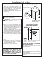
WARNING RISK OF FIRE
• To reduce the risk of severe injury or death, follow all installation
instructions.
&ORWKHVGU\HULQVWDOODWLRQPXVWEHSHUIRUPHGE\DTXDOL¿HGLQVWDOOHU
• Install the clothes dryer according to these instructions and in accordance
with local codes.
• This dryer must be exhausted to the outdoors.
•
Use only rigid metal 4” diameter ductwork inside the dryer cabinet and use
only UL approved transition ducting between the dryer and the home duct.
'2127LQVWDOODFORWKHVGU\HUZLWKÀH[LEOHSODVWLFGXFWLQJPDWHULDOV,I
ÀH[LEOHPHWDOVHPLULJLGRUIRLOW\SHGXFWLVLQVWDOOHGLWPXVWEH8/OLVWHG
and installed in accordance with the instructions found in “Connecting
7KH'U\HU7R+RXVH9HQWµRQSDJHVRIWKLVPDQXDO)OH[LEOHYHQWLQJ
materials are known to collapse, be easily crushed, and trap lint. These
FRQGLWLRQVZLOOREVWUXFWGU\HUDLUÀRZDQGLQFUHDVHWKHULVNRI¿UH
• Do not install or store this appliance in any location where it could be
exposed to water and or weather.
6DYH WKHVH LQVWUXFWLRQV ,QVWDOOHUV %H VXUH WR OHDYH WKHVH LQVWUXFWLRQV
ZLWKWKHFXVWRPHU
NOTE: Installation and service of this dryer requires basic
mechanical and electrical skills. It is your responsibility to contact
DTXDOL¿HGLQVWDOOHUWRPDNHWKHHOHFWULFDOFRQQHFWLRQV
Installation
Instructions
Electric Dryer
01
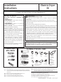
BEFORE YOU BEGIN
Read these instructions completely and
carefully.
• IMPORTANT- Save these instructions
for local inspector’s use.
• IMPORTANT- Observe all governing
codes and ordinances.
• Note to Installer - %H VXUH WR OHDYH WKHVH
instructions with the customer.
• Note to Customer - Keep these instructions
with your Owner’s Manual for future reference.
%HIRUHWKHROGGU\HULVUHPRYHGIURPVHUYLFH
or discarded, remove the dryer door.
• Service information and the wiring diagram
are located in the control console.
• Do not allow children on or in the appliance.
Close supervision of children is necessary
when the appliance is used near children.
• Install the dryer where the temperature is
DERYH)IRUVDWLVIDFWRU\RSHUDWLRQRIWKH
dryer control system.
• Product failure due to improper installation is
not covered under the Warranty.
TOOLS YOU
WILL NEED
PHILLIPS SCREWDRIVER
SLIP JOINT PLIERS
LEVEL
FLAT BLADE SCREWDRIVER
MATERIALS YOU WILL NEED
GLOVES
SAFETY
GLASSES
DRYER POWER
CORD KIT
(NOT PROVIDED
WITH DRYER)
4" DUCT
CLAMPS (2)
OR
4" SPRING
CLAMPS (2)
EXHAUST
HOOD
3/4" STRAIN
RELIEF
UL RECOGNIZED
4" DIA. METAL
ELBOW
4" DIA. FLEXIBLE METAL (SEMI-RIGID)
UL LISTED TRANSITION DUCT
(IF NEEDED)
KIT WX08X10077 (INCLUDES 2 ELBOWS)
4" DIA. METAL DUCT
(RECOMMENDED)
4" DIA. FLEXIBLE METAL (FOIL TYPE)
UL LISTED TRANSITION DUCT
(IF NEEDED.)
DUCT TAPE
UL RATED
120/240V,30A
WITH 3 OR 4 PRONGS.
IDENTIFY THE PLUG
TYPE AS PER THE
HOUSE RECEPTACLE
BEFORE PURCHASING
LINE CORD.
4” COVER PLATE (IF NEEDED
(KIT WE1M454)
234D2006P001 31-16311 03-13 GE
Step 1 Prepare the area and exhaust for installation of new dryer
VHHVHFWLRQ
6WHS &KHFNDQGHQVXUHWKHH[LVWLQJH[WHUQDOH[KDXVWLVFOHDQVHH
VHFWLRQDQGPHHWVDWWDFKHGLQVWDOODWLRQVSHFL¿FDWLRQVVHH
VHFWLRQ
6WHS 5HPRYHWKHIRDPVKLSSLQJSDGVVHHVHFWLRQ
Step 4 Move the dryer to the desired location.
6WHS &RQQHFWWKHSRZHUVXSSO\VHHVHFWLRQ
6WHS &RQQHFWWKHH[WHUQDOH[KDXVWVHHVHFWLRQ
6WHS /HYHO\RXUGU\HUVHHVHFWLRQ
Step 8 Check the operation of the power supply and venting.
Step 9 Place the Owner’s Manual and the Installation Instructions in
a location where they will be noticed by the owner.
)RUDOFRYHRUFORVHWLQVWDOODWLRQVHHVHFWLRQ
)RUEDWKURRPRUEHGURRPLQVWDOODWLRQVHHVHFWLRQ
)RUPRELOHRUPDQXIDFWXUHGKRPHVHHVHFWLRQ
)RUJDUDJHLQVWDOODWLRQLIDOORZHGE\ORFDOFRGHVVHHVHFWLRQ
)RU)RUVLGHRUERWWRPH[KDXVWVHHVHFWLRQ
Questions? Call 800.GE.CARES (800.432.2737) or visit our Web site at: GEAppliances.com
In Canada, call 1.800.561.3344 or visit www.GEAppliances.ca

Installation Instructions
2
Minimum Clearance Other Than Alcove or Closet Installation
0LQLPXPFOHDUDQFHWRFRPEXVWLEOHVXUIDFHVDQGIRUDLURSHQLQJDUHLQFOHDUDQFHERWKVLGHVDQGLQUHDU&RQVLGHUDWLRQ
must be given to provide adequate clearance for installation and service.
1
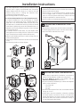
PREPARING FOR INSTALLATION OF
NEW DRYER
TIP: Install your dryer before installing your washer.
This will allow better access when installing dryer
exhaust.
REMOVING LINT FROM WALL EXHAUST
OPENING
• Remove and discard existing plastic or metal foil
transition duct and replace with UL listed transition duct.
2
ELECTRICAL CONNECTION INFORMATION
WARNING - TO REDUCE THE RISK OF
FIRE, ELECTRICAL SHOCK AND PERSONAL INJURY:
• DO NOT USE AN EXTENSION CORD OR AN
ADAPTER PLUG WITH THIS APPLIANCE.
Dryer must be electrically grounded in accordance with
local codes and ordinances, or in the absence of local
codes, in accordance with the NATIONAL ELECTRICAL
CODE, ANSI/NFPA NO. 70.
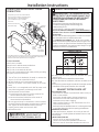
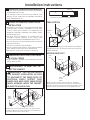
CONNECTING DRYER USING 4-WIRE
CONNECTION (MUST BE USED FOR
MOBILE HOME INSTALLATION)
NOTE: Since January 1, 1996, the National Electric code
requires that the new constructions utilize a 4-wire
connection to an electric dryer.
WARNING:
Only a 4-conductor cord shall be used when the appliance
is installed in a location where grounding through the
neutral conductor is prohibited. Grounding through
the neutral is prohibited for the new branch-circuit
installations, mobile homes, recreational vehicles, and
areas where local codes prohibit grounding through the
neutral conduction.
7XUQRȺ WKHFLUFXLWEUHDNHUV DPSRU UHPRYHWKH
dryer’s circuit fuse at the electrical box.
%H VXUH WKH GU\HU FRUG LV XQSOXJJHG IURP WKH ZDOO
receptacle.
3. Remove the power cord cover located at the lower back.
4. Remove and discard ground strap. Keep the green
ground screw for step 7.
,QVWDOOLQ8/UHFRJQL]HGVWUDLQUHOLHIWRSRZHUFRUG
HQWU\KROH%ULQJSRZHUFRUGWKURXJKVWUDLQUHOLHI
&RQQHFWSRZHUFRUGDVIROORZV
A. Connect the 2 hot lines to the outer screws of the
WHUPLQDOEORFNPDUNHG/DQG/
%&RQQHFWWKHQHXWUDOZKLWHOLQHWRWKHFHQWHURIWKH
WHUPLQDOEORFNPDUNHG1
7. Attach ground wire of power cord with the green
JURXQGVFUHZKROHDERYHVWUDLQUHOLHIEUDFNHW7LJKWHQ
DOOWHUPLQDOEORFNVFUHZVVHFXUHO\
8. Properly secure power cord to strain relief.
9. Reinstall the cover.
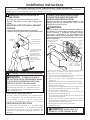
INTERNAL DUCT
OPENING
CHECK THAT EXHAUST
HOOD DAMPER OPENS
AND CLOSES FREELY.
WALL
TILT THE DRYER SIDEWAYS
AND REMOVE THE FOAM
SHIPPING PADS BY
PULLING AT THE SIDES
AND BREAKING THEM
AWAY FROM THE DRYER
LEGS. BE SURE TO
REMOVE ALL OF THE
FOAM PIECES AROUND
THE LEGS.
ELECTRICAL REQUIREMENTS
This dryer must be connected to an individual branch
FLUFXLW SURWHFWHG E\ WKH UHTXLUHG WLPHGHOD\ IXVHV RU
FLUFXLW EUHDNHUV $ IRXU RU WKUHHZLUH VLQJOH SKDVH
9 RU 9 +] DPS FLUFXLW LV UHTXLUHG
GROUNDING INSTRUCTIONS
This dryer must be connected to a grounded metal,
SHUPDQHQW ZLULQJ V\VWHP RU DQ HTXLSPHQWJURXQGLQJ
conductor must be run with the circuit conductors and
connected to the equipment grounding terminal on the
appliance.
WARNING: NEVER LEAVE THE
COVER OFF OF THE TERMINAL BLOCK.
Screws
Remove ground strap
and discard. Keep
green ground screw
Hot
Wire
Relocate
green
ground
screw
here
Green
Wire
µ8/
5HFRJQL]HG
Strain Relief
$:*PLQLPXPFRSSHUFRQGXFWRUVRU9$SRZHUVXSSO\
cord kit marked for use with dryers and provided with closed loop or
VSDGHWHUPLQDOVZLWKXSWXUQHGHQGVQRWVXSSOLHG
)XVH
Hot
Wire
Neutral
ZKLWH
Strain
Relief
%UDFNHW
Cover
Screw

Installation Instructions
3
CONNECTING DRYER USING 3-WIRE
CONNECTION
3-wire Connection
Not for use in Canada.
DO NOT use for Mobile Home Installations.
NOT for use on new construction.
NOT for use on recreational vehicles.
NOT for use in areas where local codes prohibit grounding
through the neutral conduction.
7XUQ RȺWKH FLUFXLWEUHDNHUV DPSRU UHPRYHWKH
dryer’s circuit fuse at the electrical box.
%HVXUHWKHGU\HUFRUGLVXQSOXJJHGIURPWKHZDOO
3. Remove the power cord cover located at the lower
back.
,QVWDOOLQ8/UHFRJQL]HGVWUDLQUHOLHIWRSRZHUFRUG
HQWU\KROH%ULQJSRZHUFRUGWKURXJKVWUDLQUHOLHI
&RQQHFWSRZHUFRUGDVIROORZV
A. Connect the 2 hot lines to the outer screws of the
WHUPLQDOEORFNPDUNHG/DQG/
%&RQQHFWWKHQHXWUDOZKLWHOLQHWRWKHFHQWHURI
WKHWHUPLQDOEORFNPDUNHG1
%H VXUHJURXQG VWUDSLV FRQQHFWHGWR QHXWUDOFHQWHU
terminal of block and to green ground screw on cabinet
UHDU7LJKWHQDOOWHUPLQDOEORFNVFUHZVVHFXUHO\
7. Properly secure power cord to strain relief.
8. Reinstall the cover.
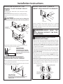
3
EXHAUST INFORMATION
WARNING - IN CANADA AND IN THE
UNITED STATES, THE REQUIRED EXHAUST DUCT
DIAMETER IS 4 in (102mm). DO NOT USE DUCT
LONGER THAN SPECIFIED IN THE EXHAUST
LENGTH TABLE.
8VLQJH[KDXVWORQJHUWKDQVSHFL¿HGOHQJWKZLOO
• Increase the drying times and the energy cost.
• Reduce the dryer life.
$FFXPXODWHOLQWFUHDWLQJDSRWHQWLDO¿UHKD]DUG
The correct exhaust installation is YOUR RESPONSIBILITY.
Problems due to incorrect installation are not covered by
the warranty.
Remove and discard existing plastic or metal foil transition
duct and replace with UL listed transition duct.
The MAXIMUM ALLOWABLE duct length and number of
bends of the exhaust system depends upon the type of duct,
QXPEHURIWXUQVWKHW\SHRIH[KDXVWKRRGZDOOFDSDQGDOO
conditions noted below. The maximum duct length for rigid
metal duct is shown in the table below.
WARNING: NEVER LEAVE THE
COVER OFF OF THE TERMINAL BLOCK.
4" DIA.
4"
4" DIA.
4" DIA.
2-1/2"
RECOMMENDED MAXIMUM LENGTH
Exhaust Hood Types
Recommended
No. of 90°
Elbows
Rigid
Metal
Rigid
Metal
90 Feet
60 Feet
45 Feet
35 Feet
25 Feet
60 Feet
45 Feet
35 Feet
25 Feet
15 Feet
0
1
2
3
4
Use only for short
run installations
EXHAUST LENGTH
• )RUHYHU\H[WUDHOERZUHGXFHWKHDOORZDEOHYHQWV\VWHP
OHQJWKE\IW
• 7ZRHOERZVZLOOEHWUHDWHGOLNHRQHHOERZ
• )RU WKH VLGHH[KDXVW LQVWDOODWLRQVDGG RQH HOERZWR WKH
chart.
• The total vent system length includes all the straight portions
DQGHOERZVRIWKHV\VWHPWUDQVLWLRQGXFWLQFOXGHG
EXHAUST SYSTEM CHECK LIST
HOOD OR WALL CAP
• Terminate in a manner to prevent back drafts or entry of
birds or other wildlife.
• Termination should present minimal resistance to
WKHH[KDXVWDLUÀRZDQGVKRXOGUHTXLUHOLWWOHRUQR
maintenance to prevent clogging.
• Never install a screen in or over the exhaust duct. This
could cause lint build up.
•
Wall caps must be installed at least 12 in. above ground level
or any other obstruction with the opening pointed down.
SEPARATION OF TURNS
)RUEHVWSHUIRUPDQFHVHSDUDWHDOOWXUQVE\DWOHDVWIW
of straight duct, including distance between last turn and
exhaust hood.
TURNS OTHER THAN 90º
2QHWXUQRIRUOHVVPD\EHLJQRUHG
7ZRWXUQVVKRXOGEHWUHDWHGDVRQHWXUQ
(DFKWXUQRYHUVKRXOGEHWUHDWHGDVRQHWXUQ
N
Screws
Green Ground Screw
& Ground Strap
Hot
Wire
µ8/
5HFRJQL]HG
Strain Relief
$:*PLQLPXPFRSSHUFRQGXFWRUVRU9$SRZHUVXSSO\
cord kit marked for use with dryers and provided with closed loop or
VSDGHWHUPLQDOVZLWKXSWXUQHGHQGVQRWVXSSOLHG
)XVH
Hot
Wire
Neutral
ZKLWH
Strain
Relief
%UDFNHW
Cover
Screw
If required, by local code, install external
JURXQGQRWSURYLGHGWRJURXQGHGPHWDO
cold water pipe, or other established
ground determined by a qualified
electrician.

Installation Instructions
4
SEALING OF JOINTS
• All joints should be tight to avoid leaks. The male end of
each section of duct must point away from the dryer.
• The duct shall not be assembled with screws or other
fastening means that extend into the duct and catch lint.
'XFW MRLQWV FDQ EH PDGH DLU DQG PRLVWXUHWLJKW E\
wrapping the overlapped joints with duct tape.
+RUL]RQWDOUXQVVKRXOGVORSHGRZQWRZDUGWKHRXWGRRUV
LQFKSHUIRRW
INSULATION
Duct work that runs through an unheated area or is near
air conditioning should be insulated to reduce condensation
DQGOLQWEXLOGXS
4
EXHAUST CONNECTION
THIS DRYER COMES READY FOR REAR
EXHAUSTING. IF SPACE IS LIMITED,
USE THE INSTRUCTIONS IN STEP 10 TO
EXHAUST DIRECTLY FROM THE SIDES OR
THE BOTTOM OF THE CABINET.
WARNING - TO REDUCE THE RISK
OF FIRE OR PERSONAL INJURY:
•
This clothes dryer must be exhausted to the outdoors.
• Use only 4” rigid metal ducting for the home exhaust
duct.
8VH RQO\ µ ULJLG PHWDO RU 8/OLVWHG ÀH[LEOH PHWDO
VHPLULJLGRUIRLOW\SHGXFWWRFRQQHFWWKHGU\HUWRWKH
home exhaust duct. It must be installed in accordance
with the instructions found in “Connecting the Dryer to
+RXVH9HQWµRQSDJHVRIWKLVPDQXDO
• Do not terminate exhaust in a chimney, a wall, a
ceiling, gas vent, crawl space, attic, under an enclosed
ÀRRURULQDQ\RWKHUFRQFHDOHGVSDFHRIDEXLOGLQJ7KH
DFFXPXODWHGOLQWFRXOGFUHDWHDSRWHQWLDO¿UHKD]DUG
• Never terminate the exhaust into a common duct with
a kitchen exhaust system. A combination of grease
DQGOLQWFUHDWHVDSRWHQWLDO¿UHKD]DUG
'RQRWXVHGXFWORQJHUWKDQVSHFL¿HGLQWKHH[KDXVW
length table. Longer ducts can accumulate lint,
FUHDWLQJDSRWHQWLDO¿UHKD]DUG
• Never install a screen in or over the exhaust duct. This
ZLOOFDXVHOLQWWRDFFXPXODWHFUHDWLQJDSRWHQWLDO¿UH
KD]DUG
• Do not assemble ductwork with any fasteners that
extend into the duct. These fasteners can accumulate
OLQWFUHDWLQJDSRWHQWLDO¿UHKD]DUG
• Do not obstruct incoming or exhausted air.
• Provide an access for inspection and cleaning of the
exhaust system, especially at turns and joints. Exhaust
system shall be inspected and cleaned at least once a
year.
CONNECTING THE DRYER TO HOUSE VENT
RIGID METAL TRANSITION DUCT
)RU EHVW GU\LQJ SHUIRUPDQFH D ULJLG PHWDO WUDQVLWLRQ
duct is recommended.
• Rigid metal transition ducts reduce the risk of crushing
and kinking.
UL-LISTED FLEXIBLE METAL (SEMI-RIGID) TRANSITION DUCT
,IULJLGPHWDOGXFWFDQQRWEHXVHGWKHQ8/OLVWHGÀH[LEOH
PHWDOVHPLULJLGGXFWLQJFDQEHXVHG.LW:;;
1HYHULQVWDOOÀH[LEOHPHWDOGXFWLQZDOOVFHLOLQJVÀRRUVRU
other enclosed spaces.
7RWDOOHQJWKRIÀH[LEOHPHWDOGXFWVKRXOGQRWH[FHHG
IHHWP
DUCT TAPE OR
DUCT CLAMP
DUCT TAPE OR
DUCT CLAMP
4" METAL DUCT CUT
TO PROPER LENGTH
EXTERNAL DUCT
OPENING
For straight line installation, connect
the dryer exhaust to the external
exhaust hood using duct tape or
clamp.
NOTE: WE STRONGLY RECOMMEND SOLID
METAL EXHAUST DUCTING. HOWEVER, IF
FLEXIBLE DUCTING IS USED IT MUST BE
UL-LISTED METAL
,
NOT PLASTIC.
STANDARD REAR EXHAUST
9HQWHGDWÀRRUOHYHO
STANDARD REAR EXHAUST
9HQWHGDERYHÀRRUOHYHO
NOTE: ELBOWS WILL PREVENT DUCT
KINKING AND COLLAPSING.

Installation Instructions
LEVELING AND STABILIZING YOUR
DRYER
6WDQGWKHGU\HUXSULJKWQHDUWKH¿QDOORFDWLRQDQGDGMXVW
the 4 leveling legs, at the corners, to ensure that the dryer
is level from side to side and front to rear.
6
ALCOVE OR CLOSET INSTALLATION
• If your dryer is approved for installation in an alcove or
closet, it will be stated on a label on the dryer back.
• The dryer MUST be vented to the outdoors. See the
EXHAUST INFORMATION sections 3 & 4.
• Minimum clearance between dryer cabinet and adjacent
ZDOOVRURWKHUVXUIDFHVLV
LQHLWKHUVLGH
3 in. front
3 in. rear
0LQLPXPYHUWLFDOVSDFHIURPÀRRUWRRYHUKHDGFDELQHWV
FHLOLQJHWFLVLQ
• Closet doors must be louvered or otherwise ventilated
DQGPXVWFRQWDLQDPLQLPXPRIVTLQRIRSHQDUHD
equally distributed. If the closet contains both a washer
DQGDGU\HUGRRUVPXVWFRQWDLQDPLQLPXPRIVTLQ
of open area equally distributed.
ELBOWS HIGHLY
RECOMMENDED
ELBOW HIGHLY
RECOMMENDED
DO
DO NOT
CRUSH
FLEXIBLE
EXHAUST
AGAINST
WALL.
DO NOT
SIT DRYER
ON FLEXIBLE
EXHAUST.
DO NOT USE
EXCESSIVE
EXHAUS
T
LENGTH
DON’T
5
)RUPDQ\DSSOLFDWLRQVLQVWDOOLQJHOERZVDWERWKWKHGU\HU
DQG WKH ZDOO LV KLJKO\ UHFRPPHQGHG VHH LOOXVWUDWLRQV
EHORZ (OERZV DOORZ WKH GU\HU WR VLW FORVH WR WKH ZDOO
without kinking and or crushing the transition duct,
PD[LPL]LQJGU\LQJSHUIRUPDQFH
• Avoid resting the duct on sharp objects.
UL-LISTED FLEXIBLE METAL (FOIL-TYPE) TRANSITION DUCT
• In special installations, it may be necessary to connect
WKH GU\HU WR WKH KRXVH YHQW XVLQJ D ÀH[LEOH PHWDO IRLO
W\SHGXFW$ 8/OLVWHGÀH[LEOH PHWDOIRLOW\SH GXFWPD\
EHXVHG21/<LQLQVWDOODWLRQVZKHUHULJLGPHWDORUÀH[LEOH
PHWDOVHPLULJLGGXFWLQJFDQQRWEHXVHG$1'ZKHUHDµ
diameter can be maintained throughout the entire length
of the transition duct.
,Q&DQDGDDQGWKH8QLWHG6WDWHVRQO\WKHÀH[LEOHPHWDO
IRLOW\SHGXFWVWKDWFRPSO\ZLWKWKH´2XWOLQHIRU&ORWKHV
'U\HU7UDQVLWLRQ'XFW6XEMHFW$µVKDOOEHXVHG
1HYHULQVWDOOÀH[LEOHPHWDOGXFWLQZDOOVFHLOLQJVÀRRUVRU
other enclosed spaces.
7RWDOOHQJWKRIÀH[LEOHPHWDOGXFWVKRXOGQRWH[FHHGIHHW
P
• Avoid resting the duct on sharp objects.
For best drying performance
1 Slide one end of the duct over the clothes dryer outlet pipe.
2. Secure the duct with a clamp.
3. With the dryer in its permanent position, extend the duct
to its full length. Allow 2” of duct to overlap the exhaust
SLSH&XW RȺDQG UHPRYHH[FHVV GXFW .HHSWKH GXFWDV
VWUDLJKWDVSRVVLEOHIRUPD[LPXPDLUÀRZ
4. Secure the duct to the exhaust pipe with the other clamp.

Installation Instructions
6
10
DRYER EXHAUST TO RIGHT, LEFT OR
BOTTOM CABINET
WARNING - BEFORE PERFORMING
THIS EXHAUST INSTALLATION, BE SURE
TO DISCONNECT THE DRYER FROM ITS
ELECTRICAL SUPPLY. PROTECT YOUR
HANDS AND ARMS FROM SHARP EDGES
WHEN WORKING INSIDE THE CABINET.
BE SURE TO WEAR GLOVES.
Detach and remove the bottom, right or left side knockout
as desired. Remove the screw inside the dryer exhaust duct
and save. Pull the duct out of the dryer.
REMOVE
SCREW
AND SAVE.
REMOVE DESIRED
KNOCKOUT
(ONE ONLY).
Cut the duct as shown and keep portion A.
9"
AB
FIXING HOLE
Through the rear opening, locate the tab in the middle of
the appliance base. Lift the tab to about 45º using a flat
blade screwdriver.
BEND TAB
UP 45
o
Reconnect the cut portion (A) of the duct to the blower
housing. Make sure that the shortened duct is aligned with
the tab in the base. U
se the screw saved previously to secure
the duct in
p
lace throu
g
h the tab on the a
pp
liance base.
RIGHT OR
LEFT SIDE
EXHAUST
PORTION "A"
FIXING
HOLE
7
BATHROOM OR BEDROOM INSTALLATION
7KHGU\HU0867EHYHQWHGWRWKHRXWGRRUV6HH(;+$867
,1)250$7,21VHFWLRQ
• The installation must conform with local codes or, in the
absence of local codes, with the NATIONAL ELECTRICAL
&2'($16,1)3$12
MOBILE OR MANUFACTURED HOME
INSTALLATION
,QVWDOODWLRQPXVWFRQIRUPWRWKH0$18)$&785('+20(
&216758&7,21 6$)(7< 67$1'$5' 7,7/( 3$57
RU ZKHQ VXFK VWDQGDUG LV QRW DSSOLFDEOH ZLWK
$0(5,&$1 1$7,21$/ 67$1'$5' )25 02%,/( +20(
$16,1)3$12%
• The dryer MUST be vented to the outdoors with the
termination securely fastened to the mobile home
VWUXFWXUH6HH(;+$867,1)250$7,21VHFWLRQ
• The vent MUST NOT be terminated beneath a mobile or
manufactured home.
7KHYHQWGXFWPDWHULDO0867%(0(7$/
•
Do not use sheet metal screws or other fastening devices
which extend into the interior of the exhaust vent.
• See section 2 for electrical connection information.
8
TAB LOCATION
ADDING NEW DUCT
GARAGE INSTALLATION (IF ALLOWED
BY LOCAL CODES)
• Dryers installed in garages must be elevated 18 inches
FPDERYHWKHÀRRU
9

Installation Instructions
7
ADDING ELBOW AND DUCT FOR
EXHAUST TO LEFT OR RIGHT SIDE OF
CABINET
• Preassemble 4” elbow with 4” duct. Wrap duct tape
around joint.
,QVHUWGXFWDVVHPEO\HOERZ¿UVWWKURXJKWKHVLGH
opening and connect the elbow to the dryer internal
duct.
CAUTION: Be sure not to pull or damage the
electrical wires inside the dryer when inserting the duct.
• Apply duct tape as shown on the joint between the
dryer internal duct and the elbow.
ADDING ELBOW FOR EXHAUST
THROUGH BOTTOM OF CABINET
• Insert the elbow through the rear opening and connect
it to the dryer internal duct.
• Apply duct tape on the joint between the dryer internal
duct and elbow, as shown above.
EXHAUST CAN
BE ADDED TO
LEFT OR RIGHT SIDE
DUCT
TAPE
DUCT
TAPE
CAUTION:
Internal duct joints must be
secured with tape, otherwise
they may separate and cause a
safety hazard.
ADDING COVER PLATE TO REAR OF
CABINET (SIDES AND BOTTOM EXHAUST)
Connect standard metal elbows and ducts to complete
WKH H[KDXVW V\VWHP &RYHU EDFN RSHQLQJ ZLWK D SODWH .LW
:(0DYDLODEOHIURP\RXUORFDOVHUYLFHSURYLGHU3ODFH
GU\HULQ¿QDOORFDWLRQ
CAUTION:
Internal duct joints must be secured with tape,
otherwise they may separate and cause a
safety hazard.
PL ATE
(KIT WE1M454)
WARNING-NEVER LEAVE THE
BACK OPENING WITHOUT THE PLATE
(KIT WE1M454).
11
CHANGING DIRECTION OF DOOR
OPENING (OPTIONAL)
2SHQWKHGRRUDQGUHPRYHWKH¿OOHUSOXJVRSSRVLWHWKHKLQJHV
With the door completely open, remove the bottom screws
from each hinge on the dryer face. Insert these screws about
half way into the TOP holes, for eachhinge on the opposite
VLGHZKHUH\RXUHPRYHGWKH¿OOHUSOXJV$SSO\¿UPSUHVVXUH
to get the screw started.
2. Loosen the top screws from each hinge on the dryer face half
way. With one hand holding the top of the door and the other
hand holding the bottom, remove the door from the dryer by
lifting it UP and OUT.
5RWDWHWKHGRRU,QVHUWWKHGRRURQWKHRSSRVLWHVLGHRI
the opening by moving the door IN and DOWN until the top
hinge and the bottom hinge are resting on the top screws
inserted in step 1.
4. Remove the remaining screws from the side of the opening
from which the door was removed. With these screws secure
each hinge at the bottom. Tighten the two top screws on each
hinge. Reinsert the plastic plugs on the side from which the
door was removed.
REMOVE THE BOTTOM SCREW
FROM EACH HINGE ON THE
DRYER FACE.
LOOSEN THE TOP SCREWS FROM EACH
HINGE ON THE DRYER FACE HALF WAY.
SECURE EACH HINGE AT THE
BOTTOM AND TIGHTEN THE TWO
TOP SREWS OF EACH HINGE.
MOVE THE DOOR IN AND DOWN UNTIL
THE TOP HINGE AND THE BOTTOM HINGE
ARE RESTING ON THE TOP SCREWS
INSERTED IN STEP 1.

8
REGISTER YOUR NEW APPLIANCE TO RECEIVE ANY
,03257$17352'8&7127,),&$7,216
Please go to www.GEAppliances.com or mail in
your product registration card.
)RUTXHVWLRQVRQLQVWDOODWLRQFDOO86RU
&DQDGD
Installation Instructions
12
SERVICING
WARNING-LABEL ALL WIRES PRIOR
TO DISCONNECTING WHEN SERVICING
CONTROLS. WIRING ERRORS CAN CAUSE
IMPROPER AND DANGEROUS OPERATION
AFTER SERVICING/INSTALLATION.
-
 1
1
-
 2
2
-
 3
3
-
 4
4
-
 5
5
-
 6
6
-
 7
7
-
 8
8


GE DNCD450EGWC Guide d'installation
- Catégorie
- Sèche-linge électriques
- Taper
- Guide d'installation
dans d''autres langues
- English: GE DNCD450EGWC Installation guide
Documents connexes
-
GE DSKS433EBWW Guide d'installation
-
GE GUD24ESSJWW Guide d'installation
-
GE GTUN275EMWW Guide d'installation
-
GE GTDX185GDCC Guide d'installation
-
GE GTDL740EDWW Guide d'installation
-
-
-
-
-
GE ZV30HSRSS Guide d'installation