ELICA ETP536SS Guide d'installation
- Catégorie
- Hottes
- Taper
- Guide d'installation
Ce manuel convient également à

Use, Care, and Installation Guide
Guide d’utilisation, d’entretien et d’installation
Guía de instalación, uso y mantenimiento
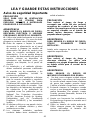
READ AND SAVE THESE INSTRUCTIONS
LISEZ CES INSTRUCTIONS ET CONSERVEZ-LES
LEA Y GUARDE ESTAS INSTRUCCIONES

English
Contents page 3
French
Sommaire page 22
Spanish
Contenido página 42

3
English
Contents
Important safety Notice................................................................................................4
Electrical & Installation requirements.........................................................................6
Electrical requirements.................................................................................................................................6
Before installing the hood.............................................................................................................................6
List of Materials.............................................................................................................7
Parts supplied...............................................................................................................................................7
Parts not supplied.........................................................................................................................................7
Dimensions and Clearances........................................................................................8
Ducting Options and Examples...................................................................................9
Venting methods ..........................................................................................................................................9
Preparation...................................................................................................................................................9
Installation...................................................................................................................10
Installation - Ductless (Recirculating) version ............................................................................................10
Description of the hood & Controls ..........................................................................16
Controls......................................................................................................................................................17
User Servicing and Maintenance Instructions.........................................................19
Cleaning.....................................................................................................................................................19
Grease Filter...............................................................................................................................................19
Replacing the light bulb..............................................................................................................................20
Charcoal Filter............................................................................................................................................20
APPROVED FOR RESIDENTIAL APPLIANCES
FOR RESIDENTIAL USE ONLY
READ AND SAVE THESE INSTRUCTIONS
PLEASE READ ENTIRE INSTRUCTIONS BEFORE PROCEEDING.
INSTALLATION MUST COMPLY WITH ALL LOCAL CODES.
IMPORTANT: Save these Instructions for the Local Electrical Inspector’s use.
INSTALLER: Please leave these Instructions with this unit for the owner.
OWNER: Please retain these instructions for future reference.
Safety Warning: Turn off power circuit at service panel and lock out panel,
before wiring this appliance.
Requirement: 120 V AC, 60 Hz. 15 or 20 A Branch Circuit

4
READ AND SAVE THESE INSTRUCTIONS
Important safety Notice
CAUTION
FOR GENERAL VENTILATING USE ONLY.
DO NOT
USE TO EXHAUST HAZARDOUS
OR EXPLOSIVE MATERIALS OR VA-
POURS.
WARNING
TO REDUCE THE RISK OF FIRE,
ELECTRIC SHOCK, OR INJURY TO
PERSONS, OBSERVE THE FOLLOWING:
A. Use this unit only in the manner intended
by the manufacturer. If you have questions,
contact the manufacturer.
B. Before servicing or cleaning the unit,
switch power off at service panel and lock
service panel disconnecting means to
prevent power from being switched on
accidentally. When the service
disconnecting means cannot be locked,
securely fasten a prominent warning
device, such as a tag, to the service
panel.
C. Installation Work and Electrical Wiring
Must Be Done By Qualified Person(s) In
Accordance With All Applicable Codes &
Standards, Including Fire-rated
Construction.
D. Sufficient air is needed for proper
combustion and exhausting of gases
through the flue (Chimney) of fuel burning
equipment to prevent back- drafting.
Follow the heating equipment
manufacturers guideline and safety
standards such as those published by the
National Fire Protection Association
(NFPA), the American Society for
Heating, Refrigeration and Air
Conditioning Engineers (ASHRAE), and
the local code authorities.
E. When cutting or drilling into wall or
ceiling, do not damage electrical wiring
and other hidden utilities.
F. Ducted systems must always be vented
to the outdoors.
CAUTION
To reduce risk of fire and to properly
exhaust air, be sure to duct air outside -
do not vent exhaust air into spaces within
walls, ceilings, attics, crawl spaces, or
garages.
WARNING
TO REDUCE THE RISK OF FIRE, USE
ONLY METAL DUCT WORK.
Install this hood in accordance with all
requirements specified.
WARNING
To Reduce The Risk Of Fire Or Electric
Shock, Do Not Use This Hood With Any
External Solid State Speed Control
Device.
WARNING
TO REDUCE THE RISK OF A RANGE TOP
GREASE FIRE.
a) Never leave surface units unattended at
high settings. Boilovers cause smoking
and greasy spillovers that may ignite.
Heat oils slowly on low or medium
settings.
b) Always turn hood ON when cooking at
high heat or when flambeing food (I.e.
Crepes Suzette, Cherries Jubilee,
Peppercorn Beef Flambe’).
c) Clean ventilating fans frequently. Grease
should not be allowed to accumulate on
fan or filter.
d) Use proper pan size. Always use
cookware appropriate for the size of the
surface element.
WARNING
TO REDUCE THE RISK OF INJURY TO
PERSONS, IN THE EVENT OF A RANGE
TOP GREASE FIRE, OBSERVE THE
FOLLOWING: *
)
a) SMOTHER FLAMES with a close-fitting
lid, cookie sheet, or other metal tray, then

5
turn off the gas burner or the electric
element. BE CAREFUL TO PREVENT
BURNS. If the flames do not go out
immediately, EVACUATE AND CALL
THE FIRE DEPARTMENT.
b) NEVER PICK UP A FLAMING PAN - you
may be burned.
c) DO NOT USE WATER, including wet
dishcloths or towels - a violent steam
explosion will result.
d) Use an extinguisher ONLY if:
1) You know you have a class ABC
extinguisher, and you already know how to
operate it.
2) The fire is small and contained in
the area where it started.
3) The fire department is being
called.
4) You can fight the fire with your
back to an exit.
*
) Based on "Kitchen Firesafety Tips"
published by NFPA.
OPERATION
a. Always leave safety grills and filters in
place. Without these components, operating
blowers could catch onto hair, fingers and
loose clothing.
The manufacturer declines all responsibility
in the event of failure to observe the
instructions given here for installation,
maintenance and suitable use of the product.
The manufacturer further declines all
responsibility for injury due to negligence and
the warranty of the unit automatically expires
due to improper maintenance.

6
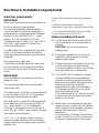
Electrical & Installation requirements
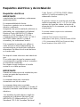
Electrical requirements
IMPORTANT
Observe all governing codes and ordinances.
It is the customer’s responsibility:
To contact a qualified electrical installer.
To assure that the electrical installation is
adequate and in conformance with National
Electrical Code, ANSI/NFPA 70 — latest
edition*, or CSA Standards C22.1-94,
Canadian Electrical Code, Part 1 and C22.2
No.0-M91 - latest edition** and all local
codes and ordinances.
If codes permit and a separate ground wire is
used, it is recommended that a qualified
electrician determine that the ground path is
adequate.
Do not ground to a gas pipe.
Check with a qualified electrician if you are
not sure range hood is properly grounded.
Do not have a fuse in the neutral or ground
circuit.
IMPORTANT
Save Installation Instructions for electrical
inspector’s use.
The range hood must be connected with
copper wire only.
The range hood should be connected directly
to the fused disconnect (Or circuit breaker)
box through metal electrical conduit.
Wire sizes must conform to the requirements
of the National Electrical Code ANSI/NFPA
70 — latest edition*, or CSA Standards
C22.1-94, Canadian Electrical Code Part 1
and C22.2 No. 0-M91 - latest edition** and all
local codes and ordinances.
A U.L.- or C.S.A.-listed conduit connector
must be provided at each end of the power
supply conduit (at the range hood and at the
junction box).
Copies of the standards listed may be obtained
from:
* National Fire Protection Association
Batterymarch Park Quincy, Massachusetts 02269
** CSA International 8501 East Pleasant Valley
Road Cleveland, Ohio 44131-5575
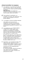
Before installing the hood
1. For the most efficient air flow exhaust,
use a straight run or as few elbows as
possible.
CAUTION: Vent unit to outside of
building, only.
2. At least two people are necessary for
installation. Wear gloves to protect
against sharp edges.
3. Fittings material is provided to secure the
hood to most types of walls/ceilings,
consult a Qualified Installer, check if they
perfectly fit with your cabinet/wall.
4. COLD WEATHER installations should
have an additional backdraft damper
installed to minimize backward cold air
flow and a nonmetallic thermal break to
minimize conduction of outside
temperatures as part of the ductwork.
The damper should be on the cold air
side of the thermal break.
The break should be as close as possible
to where the ducting enters the heated
portion of the house.
5. Make up air: Local building codes may
require the use of Make-Up Air Systems
when using Ducted Ventilation Systems
greater than specified CFM of air
movement.
The specified CFM varies from locale to
locale. Consult your HVAC professional
for specific requirements in your area.

7
List of Materials
Parts supplied
• Blower unit housing x 2
• Aesthetic cover x 1
• Glass x 1
• Stainless steel mesh filter x 2
• Halogen light bulb x 2
• Hardware Packet:
Support bracket with cables and hooking
brackets x 2
Cover x 2
Template
Use, Care and Installation Guide
Torx adapter T10 x 1
Torx adapter T20 x 1
5x45 screws x 6 (To attach support
bracket to ceiling)
3,5x6,5 screws x 8 (2 To attach j-box to
support bracket, 6 for fixing hood to
supporto bracket)
Knob x 6 (For fixing the glass)
Crescent-shaped washers x 6 (For fixing
the glass)
Control lever
Parts not supplied
• Conduit and all tools required for
installation.

8
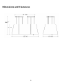
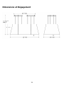
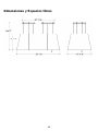
Dimensions and Clearances

9
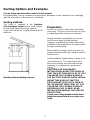
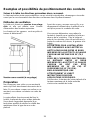
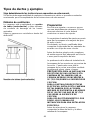
Ducting Options and Examples
Closely follow the instructions set out in this manual.
All responsibility, for any eventual inconveniences, damages or fires caused by not complying
with the instructions in this manual, is declined.
Venting methods
The hood is supplied in the Ductless
(Recirculating) version and is used without
an extracted fumes discharger conduit .
Fumes and steam are recycled through the F
deflector.
Preparation
Do not cut a joist or stud unless absolutely
necessary. If a joist or stud must be cut, then
a supporting frame must be constructed.
Fittings material is provided to secure the
hood to most types of walls/ceilings.
However, a qualified technician must verify
suitability of the materials in accordance with
the type of wall/ceiling.
Before making cutouts, make sure there is
proper clearance within the ceiling or wall for
exhaust vent.
Hood installation height above cooktop is the
users preference. The lower the hood is
above the cooktop, the more efficient the
capturing of cooking odors, grease and
smoke.
CAUTION: FOR GAS RANGES
INSTALLATION: MOUNT THIS HOOD SO
THAT THE BOTTOM EDGE IS AT 30" (76,2
CM) ABOVE THE COOKING SURFACE.
FOR ELECTRIC RANGES INSTALLATION:
MOUNT THIS HOOD SO THAT THE
BOTTOM EDGE IS NOT LESS THAN 24"
(61 CM) AND NOT MORE THAT 30" (76,2
CM) ABOVE THE COOKING SURFACE.
HOUSEHOLD USE. PLEASE, READ
INSTALLATION MANUAL FOR SPECIFIC
APPLICATION.
Check your ceiling height and the hood
height maximum before you select your
hood.

10
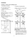
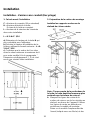
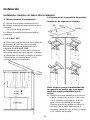
Installation
Installation - Ductless (Recirculating) version
1. Pre-installation calculations
C = Counter Height (36" standard)
H = Prefered Height of Hood
Bottom above counter
L = Chimney Structure Height, your
installation.
L = X-Y-H+1" 3/16
a) Select a hood preference height H that is
comfortable for the user.
b) Calculate Hood height your installation L =
X-Y-H+1" 3/16 .
c) Confirm that H is within the range of min to
max H found for your model (See
“Dimensions and clearances” paragraph). If
not adjust your installation.
2. Preparation of mounting surface
Installing supports above ceiling drywall.
Note: Take into consideration the hood
depth; the hood could be much deeper
than the cooktop.
a. Mark center lines of cooktop or range on
ceiling above. Use centerlines marked on
ceiling to position the mounting template.
Note location of hood front (that indicated
with a printed arrow), side, and mounting
holes indicated on template.
Note: Remember that printed arrow on

11
template corresponds to front of the hood
and consequently to side where control
panels will be located at the end of
installation)
b. Remove and save template. Cut and
remove ceiling drywall. Install suitable
length 2" x 4" lumber between joists to
provide support bracket mounting points
as shown above. Use template for
dimensions and required clearance.
Make sure to affix the added lumber
firmly and level. Consult a professional if
you have difficulties or your installation is
unique. Consult template and Figs.above.
c. Install drywall; then refinish ceiling.
Determine the required position for the
conduit and cut a 1-1/4" (3.2 cm) hole at
this location.
Run wires through hole according the
National Electrical Code or CSA
Standards and local codes and
ordinances.
d. Tape Template in place and mount the
support bracket with wood screws
(Supplied in mounting hardware kit) on
locations marked on template, then
remove template.
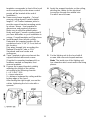
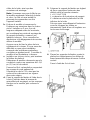
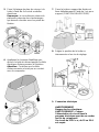
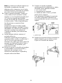
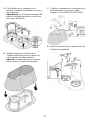
3. Prepare the support bracket, suitably
adjusting the length of the cables
according to the following formula:
L = X-Y-H+1" 3/16
L = truss extension
X = distance between the ceiling and the
bottom edge of the hood
After finding the right length, secure the
cables, tightening the lock nuts with a
spanner.
4. Apply the support brackets on the ceiling,
passing the cables for the electrical
connection through the middle hole.
Fix with 6 wood screws.
5. Fix the lighting unit to the hood with 6
screws and crescent-shaped washers.
Note: The inside rim of the lighting unit
has chamfers which must match the fixing
places.

12
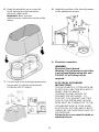
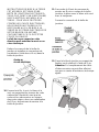
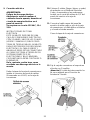
6. Apply the aesthetic cap to cover the
hood, passing the interconnection
electrical cable inside.
Important: Make sure the
interconnection cable does not touch the
lamps.
7. Fix the hood to the hooking brackets and
secure with 1 screw for each bracket
(COMPULSORY FIXING).
8. Adjust the position of the hood by means
of the adjustment screws.
9. Electrical connection
WARNING
Electrical Shock Hazard
Warning: Turn off power circuit at the
service panel before wiring this unit.
120 VAC, 15 or 20 Amp circuit
required.
ELECTRICAL GROUNDING
INSTRUCTIONS
THIS APPLIANCE IS FITTED WITH AN
ELECTRICAL JUNCTION BOX WITH 3
WIRES, ONE OF WHICH
(GREEN/YELLOW) SERVES TO
GROUND THE APPLIANCE. TO
PROTECT YOU AGAINST ELECTRIC
SHOCK, THE GREEN AND YELLOW
WIRE MUST BE CONNECTED TO THE
GROUNDING WIRE IN YOUR HOME
ELECTRICAL SYSTEM, AND IT MUST
UNDER NO CIRCUMSTANCES BE CUT
OR REMOVED.
Failure to do so can result in death or
electrical shock.

13
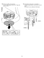
Remove the Junction box cover and
install the conduit connector (cULus
listed) in junction box.
10. Run 3 wires; black, white and green
,according to the National Electrical Code
and local codes and ordinances, in 1/2"
conduit from service panel to junction
box.
11. Connect black wire from service panel to
black or red in junction box, white to white
and green to green-yellow.
Close and secure junction box cover.
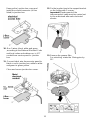
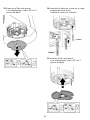
12. Fix the junction box to the support bracket
on the ceiling with 2 screws.
Important! Replacement of the
interconnection cable must be carried out
by the authorised after-sales technical
service.
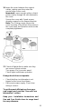
13. Remove the grease filter.
For unlocking, rotate the 3 fixing pins by
90°.

14
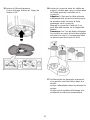
14. Fit the control shaft in the correct position
by pushing it upwards.
Connect the electricity.
15. Insert the grease filter.
For locking, rotate the 3 fixing pins by
90°.

15
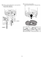
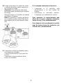
16. Insert the cover between the support
cables, making sure they enter the
special slots on the cover.
Important! Leave enough cable so that it
passes easily through the slot obtained in
the cover.
Secure the cover with 3 grub screws
already screwed on the support bracket.
Note: The 3 fixing screws secure the
cover by virtue of the friction they exert on
the cover itself, and therefore must not be
completely tightened.
17. Check all light bulbs to make sure they
are secure in their sockets.
Turn power (On) in service panel.
Check lights and blower operation.
If range hood does not operate:
• Check that the circuit breaker is not
tripped or the house fuse blown.
• Disconnect power supply. Check that
wiring is correct.
To get the most efficient use from your
new range hood, read the “Use and Care
Information” section.
Keep your Installation Instructions and
Use and Care Guide close to range hood
for easy reference.

16
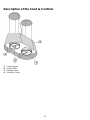
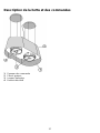
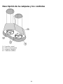
Description of the hood & Controls
1 Control panel
2 Grease filter
3 Halogen lamp
4 Aesthetic cover

17
Controls
Use the high suction speed in cases of
concentrated kitchen vapours. It is
recommended that the cooker hood suction
is switched on for 5 minutes prior to cooking
and to leave in operation during cooking and
for another 15 minutes approximately after
terminating cooking.
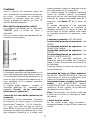
Description of control panel
The hood is equipped with a “TOUCH”
device to control the lights and speed.
For the correct use please carefully read the
intructions below.
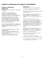
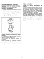
Automatic start-up function
The hood is equipped with a temperature
sensor which activates the motor to the first
suction speed (power) in the event that the
room temperature in the surrounding area is
higher than 70°C.
The user may switch off or modify the suction
speed (power) (see paragraph “suction
speed (power) control”).
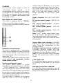
Suction speed (power) control
The suction speed (power) is cyclical
depending on the speed sequence “stand-by
– 1-2-3-4- Stand by -1-2-...” therefore every
time the T1 button is pressed on the control
panel, the suction speed (power) is increased
by one level, in order to switch off (stand-by)
if the button is pressed again when the hood
is in suction speed (power) 4.
The hood may be switched off (stand-by)
while the hood is set on any speed by
holding down the T1 button on the control
panel for a bit longer (more than 3 seconds).
The hood's suction speed (power) may be
determined as the control panel is equipped
with a LED light that changes colors as
follows, depending on the suction speed
(power):
Hood in stand-by: LED LIGHT SWITCHED
OFF
1
st
suction speed (power) -GREEN LED
LIGHT
2
nd
suction speed (power) – ORANGE
LED LIGHT (amber)
3
rd
suction speed (power) - RED LED
LIGHT
4
th
suction speed (power) - RED LED
LIGHT (FLASHING)
Note: The 4
th
suction speed (power) stays
on for 5 minutes, after which the suction
motor will position itself on the 2
nd
speed.
If pressed again, the suction motor will switch
off (stand-by).
Grease filters need cleaning: FLASHING
GREEN LED light (read instructions found
under “Reset and configuration for filter
saturation signal”)
Coal filters must be cleaned or replaced:
FLASHING ORANGE (amber) LED light
(read instructions found under “Reset and
configuration for filter saturation signal”)
Note: The reset procedure may be activated
by both the control panel and the remote
control.
Center light check
The center light may be switched on and off
by pressing the T2 button on the control
panel.
Side light check (when scheduled)
The side lights may be switched on and off
by pressing AND HOLDING DOWN the T2
button on the control panel.

18
Reset and configuration for filter
saturation signal
Switch on hood to any speed (see above
paragraph “Suction speed (power) selection”)
Reset grease filter saturation signal
(FLASHING GREEN LIGHT on control
panel)
First proceed with filter maintenance as
described in corresponding paragraph.
Press and hold down (for more than 3
seconds) the T1 button on the control panel,
the LED light will stop flashing indicating that
the signal reset has been carried out, the
hood will switch off.
Reset coal filter saturation signal
(FLASHING ORANGE (amber) LED light)
First proceed with filter maintenance as
described in corresponding paragraph.
Press and hold down (for more than 3
seconds) the T1 button on the control panel,
the LED light will stop flashing indicating that
the signal reset has been carried out, the
hood will switch off.
Coal filter saturation signal disactivaction
(for particular applications)
Switch off hood (see above paragraph
“suction speed (power) selection”).
Press and hold down (for more than 5
seconds) the T1 button on the control panel,
the LED light will start flashing GREEN
indicating that the coal filter saturation signal
has been disactivated.
In order to reactivate the coal filter saturation
signal, repeat operation, the LED light will
flash ORANGE (amber)

19
User Servicing and Maintenance Instructions
ATTENTION! Before performing any maintenance operation, isolate the hood from the electrical
supply by switching off at the connector and removing the connector fuse.
Or if the appliance has been connected through a plug and socket, then the plug must be
removed from the socket.
Cleaning
The cooker hood should be cleaned regularly
(at least with the same frequency with which
you carry out maintenance of the fat filters)
internally and externally. Clean using the
cloth dampened with neutral liquid detergent.
Do not use abrasive products. DO NOT USE
ALCOHOL!
WARNING: Failure to carry out the basic
cleaning recommendations of the cooker
hood and replacement of the filters may
cause fire risks.
Therefore, we recommend oserving these
instructions.
The manufacturer declines all responsibility
for any damage to the motor or any fire
damage linked to inappropriate maintenance
or failure to observe the above safety
recommendations.
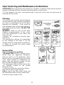
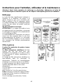
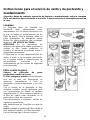
Grease Filter
Traps cooking grease particles.
The grease filter must be cleaned once a
month using non aggressive detergents,
either by hand or in the dishwasher, which
must be set to a low temperature and a short
cycle. When washed in a dishwasher, the
grease filter may discolour slightly, but this
does not affect its filtering capacity.
The metal grease filter and the carbon filter
are installed coupled at the bottom
(extraction area).
To remove or refit them, proceed as follows:
a+c. turn the three screws 1/4 turn.
b+d+e. remove the filter holder frame and
the metal grease filter (and the carbon filter).
Proceed in reverse order to refit.

20
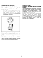
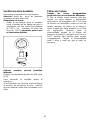
Replacing the light bulb
Disconnect the hood from the electricity.
Warning! Prior to touching the light bulbs
ensure they are cooled down.
Replace Lights
• Remove the damaged light (twist counter
clockwise) and replace with a new 120
Volt, 50 Watt (maximum) 50° halogen
light made for a GU10 base, suitable for
use in open luminarie.
Some models envisage lateral lamps:
Replace them with identical forms of 40W
(E12) max).
Remove cover to access the lamp housing.
If the lights do not work, make sure that the
lamps are fitted properly into their housings
before you call for technical assistance.
Charcoal Filter
It absorbs unpleasant odours caused by
cooking.
The charcoal filter can be washed once every
two months using hot water and a suitable
detergent, or in a dishwasher at 65°C (if the
dishwasher is used, select the full cycle
function and leave dishes out).
Eliminate excess water without damaging the
filter, then remove the mattress located
inside the plastic frame and put it in the oven
for 10 minutes at 100° C to dry completely.
Replace the mattress every 3 years and
when the cloth is damaged.
La page est en cours de chargement...
La page est en cours de chargement...
La page est en cours de chargement...
La page est en cours de chargement...
La page est en cours de chargement...
La page est en cours de chargement...
La page est en cours de chargement...
La page est en cours de chargement...
La page est en cours de chargement...
La page est en cours de chargement...
La page est en cours de chargement...
La page est en cours de chargement...
La page est en cours de chargement...
La page est en cours de chargement...
La page est en cours de chargement...
La page est en cours de chargement...
La page est en cours de chargement...
La page est en cours de chargement...
La page est en cours de chargement...
La page est en cours de chargement...
La page est en cours de chargement...
La page est en cours de chargement...
La page est en cours de chargement...
La page est en cours de chargement...
La page est en cours de chargement...
La page est en cours de chargement...
La page est en cours de chargement...
La page est en cours de chargement...
La page est en cours de chargement...
La page est en cours de chargement...
La page est en cours de chargement...
La page est en cours de chargement...
La page est en cours de chargement...
La page est en cours de chargement...
La page est en cours de chargement...
La page est en cours de chargement...
La page est en cours de chargement...
La page est en cours de chargement...
La page est en cours de chargement...
La page est en cours de chargement...
La page est en cours de chargement...
La page est en cours de chargement...
La page est en cours de chargement...
La page est en cours de chargement...
-
 1
1
-
 2
2
-
 3
3
-
 4
4
-
 5
5
-
 6
6
-
 7
7
-
 8
8
-
 9
9
-
 10
10
-
 11
11
-
 12
12
-
 13
13
-
 14
14
-
 15
15
-
 16
16
-
 17
17
-
 18
18
-
 19
19
-
 20
20
-
 21
21
-
 22
22
-
 23
23
-
 24
24
-
 25
25
-
 26
26
-
 27
27
-
 28
28
-
 29
29
-
 30
30
-
 31
31
-
 32
32
-
 33
33
-
 34
34
-
 35
35
-
 36
36
-
 37
37
-
 38
38
-
 39
39
-
 40
40
-
 41
41
-
 42
42
-
 43
43
-
 44
44
-
 45
45
-
 46
46
-
 47
47
-
 48
48
-
 49
49
-
 50
50
-
 51
51
-
 52
52
-
 53
53
-
 54
54
-
 55
55
-
 56
56
-
 57
57
-
 58
58
-
 59
59
-
 60
60
-
 61
61
-
 62
62
-
 63
63
-
 64
64


ELICA ETP536SS Guide d'installation
- Catégorie
- Hottes
- Taper
- Guide d'installation
- Ce manuel convient également à
dans d''autres langues
- English: ELICA ETP536SS Installation guide
- español: ELICA ETP536SS Guía de instalación