
OWNER’S MANUAL
OM-6608 199 859
April 2000
BWC-3
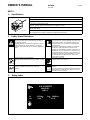
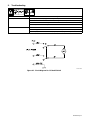
1. Specifications
Recirculating Coolant System For Water-Cooled GTAW Torches And GMAW Guns
Use With Guns/Torches Rated Up To 600 Amperes
IP Rating: 23
3 gal (11.4 L) Coolant Tank Capacity;
Maximum Cooling Capacity: 14,000 BTU/hr At 1.25 qt/min (1.2 L/min)
Dimensions: 23 in (584 mm) Long, 12 in (305 mm) Wide, 13-1/4 in (337 mm) HighDimensions: 23 in (584 mm) Long, 12 in (305 mm) Wide, 13-1/4 in (337 mm) High
Weight: 39 lb (18 kg)
ST-801 189-A
115 Volt Models Use 5.9 Amperes, 50/60 Hertz, Single-Phase Input Power
230 Volt Models Use 3 Amperes, 50/60 Hertz, Single-Phase Input Power
2. Safety Symbol Definitions
Means Warning! Watch Out! There are possible hazards
with this procedure! The possible hazards are shown in
the adjoining symbols.
Symbole graphique d’avertissement! Attention! Cette pro-
cédure comporte des risques possibles! Les dangers
éventuels sont représentés par les symboles graphiques
joints.
Have only trained and qualified persons install, operate,
or service this unit. Call your distributor if you do not un-
derstand the directions. For WELDING SAFETY and
EMF information, read wire feeder and welding power
source manuals.
L’installation, l’exploitation et l’entretien de cet appareil
doivent être confiés uniquement à des personnes
qualifiées et convenablement formées. S’adresser à un
distributeur si l’on ne comprend pas les directives. Pour
des renseignements ayant trait à la SÉCURITÉ lors du
soudage et aux champs électromagnétiques, consulter
les manuels traitant les dévidoirs et les sources de
courant pour le soudage.
Beware of electric shock from wiring.
Attention! Risque d’électrocution due au contact avec des
fils.
Beware of moving parts.
Attention! Pièces en mouvement.
Wear safety glasses with side shields.
Porter des lunettes de sécurité avec protections
latérales.
Recycle or dispose of used coolant in an environmentally
safe way.
Recycler ou éliminer tout liquide de refroidissement usé
conformément aux méthodes prescrites pour assurer la
protection de l’environnement.
3. Rating Label
S/N: KG085472
043007015
115
5.9
BWC-3
Hz50/60
IP 23
V
U
1
=
A I
1
=
1
NRTL/C
LR5071

OM-6608 Page 2
4. Symbols And Definitions
A
Amperes Alternating Current Voltage Input
Circulating Unit
With Coolant Pump
V
Volts
Water (Coolant) In-
put
Water (Coolant)
Output
Line Connection
Protective Earth
(Ground)
IP
Degree Of
Protection
I
1
Primary Current
Hz
Hertz
On Off
U
1
Primary Voltage Single Phase
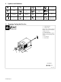
5. Preparing Cooling Unit For Use
ST-801 193-B
1 Coolant Out Hose
2 Coolant In Hose
Fittings have 5/8-18 left-hand
threads. Connect hoses with prop-
er fittings as shown.
3 Coolant Tank Cap
Maintain coolant level at approxi-
mately 1 in (25 mm) below top of fill-
er neck.
4 Flow Indicator
5 Power Switch
Tools Needed:
5/8 in
1
2
3
4 5

OM-6608 Page 3
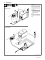
6. Connections
ST-801 190-B / ST-801 191-B
1 Lift -Eye
If placing cooling unit on welding
power source, slots are provided in
bottom of unit so it fits over lift-eye.
To prevent overheating, make sure
cooling unit is positioned so airflow
is not restricted.
Y If welding power source has
a water valve, do not connect
hoses to water valve. Con-
nect hoses as shown.
Operation:
Turn power switch On. Flow indica-
tor spins to indicate that at least
0.53 qt/min (0.5 L/min) of coolant is
flowing.
GTAW Connections
GMAW Connections
1

OM-6608 Page 4
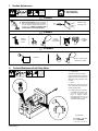
7. Routine Maintenance
Y Disconnect power
before maintaining.
3 Months
Blow Out Heat
Exchanger Fins
Y Clean coolant strainer. Severe conditions
may require more frequent cleaning (continu-
ous use, high/low temperatures, dirty envi-
ronment, etc.). Failure to properly clean
coolant strainer voids pump warranty.
6 Months
Replace
Cracked
Hoses
Replace
Unreadable
Labels
Change
Coolant (If
Using Water)
12 Months
Oil Motor
Change Coolant (If Using
Commercial Coolant)
3/8 in
Tools Needed:
8. Coolant Maintenance And Oiling Motor
ST-801 195-B / Ref. ST-801 194
1 Coolant Filter
Unscrew housing to clean filter.
Changing coolant: Drain coolant by
tipping unit forward. Fill with clean
water and run for 10 minutes. Drain
and refill.
2 Motor
Remove plugs and put about 15
drops of SAE 20 motor oil into each
oil port. Replace plugs.
. If replacing hoses, use hoses
compatible with ethylene gly-
col, such as Buna-n, Neo-
prene, or Hypalon. NOTE:
Oxy-acetylene hoses are not
compatible with any product
containing ethylene glycol.
1
2

OM-6608 Page 5
9. Troubleshooting
Trouble Remedy
Coolant system does not work. Be sure input power cord is plugged in to energized receptacle.
Check line fuses or circuit breaker, and fuses F1, F2 if applicable, and replace or reset if necessary.
Motor overheated. Unit starts running when motor has cooled.
Have Factory Authorized Service Agent check Power switch S1 and motor Mot.
Decreased or no coolant flow. Add coolant.
Check for clogged hoses or coolant filter. Clean filter or clean / replace hoses if necessary.
Disconnect pump, and check for sheared coupling. Replace coupling if necessary.
SA-135 796-D
Figure 9-1. Circuit Diagram For 115 And 230 Volt

OM-6608 Page 6
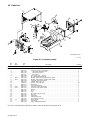
10. Parts List
*Included in Item 20
ST-802 621
Figure 10-1. Complete Assembly
Description
Part
No.
Dia.
Mkgs.
Item
No.
Figure 10-1. Complete Assembly
Quantity
1 BWC-001 Hood 1. . . . . . . . . . . . . . . . . . . . . . . . . . . . . . . . . . . . . . . . . . . . . . . . . . . . . . . . . . . . . . . . . . . . . . . . . . . . . . . . . . . . . . . . . . . . . . . . . .
2 BWC-002 Pump with Clamps, (consisting of) 1. . . . . . . . . . . . . . . . . . . . . . . . . . . . . . . . . . . . . . . . . . . . . . . . . . . . . . . . . . . . . . . . . . . . . . . . .
3 BWC-003 Hose Fitting, M 3/8 tbg x 3/8 2. . . . . . . . . . . . . . . . . . . . . . . . . . . . . . . . . . . . . . . . . . . . . . . . . . . . . . . . . . . . . . . . . . . . . . . . . . . . . .
4 BWC-004 Drive Pump Coupler 1. . . . . . . . . . . . . . . . . . . . . . . . . . . . . . . . . . . . . . . . . . . . . . . . . . . . . . . . . . . . . . . . . . . . . . . . . . . . . . . . . . . . .
5 BWC-005 Hose Fitting 1. . . . . . . . . . . . . . . . . . . . . . . . . . . . . . . . . . . . . . . . . . . . . . . . . . . . . . . . . . . . . . . . . . . . . . . . . . . . . . . . . . . . . . . . . . . .
6 BWC-006 Hose Clamp, .375 – .450 clip 1. . . . . . . . . . . . . . . . . . . . . . . . . . . . . . . . . . . . . . . . . . . . . . . . . . . . . . . . . . . . . . . . . . . . . . . . . . . . . .
7 BWC-007 No. 1 Braided HOSE (1/4” ID) 1. . . . . . . . . . . . . . . . . . . . . . . . . . . . . . . . . . . . . . . . . . . . . . . . . . . . . . . . . . . . . . . . . . . . . . . . . . . . .
8 MOT BWC-008 MOTOR, 1/4hp 115VAC 50/60Hz (115V model) 1. . . . . . . . . . . . . . . . . . . . . . . . . . . . . . . . . . . . . . . . . . . . . . . . . . . . . . . . .
8 MOT BWC-026 MOTOR, 1/4hp 230VAC 50/60Hz (230V model) 1. . . . . . . . . . . . . . . . . . . . . . . . . . . . . . . . . . . . . . . . . . . . . . . . . . . . . . . . .
9 BWC-009 Fan Blade, (setscrew included) 1. . . . . . . . . . . . . . . . . . . . . . . . . . . . . . . . . . . . . . . . . . . . . . . . . . . . . . . . . . . . . . . . . . . . . . . . . . . .
10 BWC-010 TUBING, 3/8” x 5/8” x 18” 2. . . . . . . . . . . . . . . . . . . . . . . . . . . . . . . . . . . . . . . . . . . . . . . . . . . . . . . . . . . . . . . . . . . . . . . . . . . . . . . . .
11 BWC-011 CLAMP, .718 x .276 wide 10. . . . . . . . . . . . . . . . . . . . . . . . . . . . . . . . . . . . . . . . . . . . . . . . . . . . . . . . . . . . . . . . . . . . . . . . . . . . . . . . .
12 BWC-012 Rear Panel 1. . . . . . . . . . . . . . . . . . . . . . . . . . . . . . . . . . . . . . . . . . . . . . . . . . . . . . . . . . . . . . . . . . . . . . . . . . . . . . . . . . . . . . . . . . . . .
13 BWC-013 Strain Relief Bushing 1. . . . . . . . . . . . . . . . . . . . . . . . . . . . . . . . . . . . . . . . . . . . . . . . . . . . . . . . . . . . . . . . . . . . . . . . . . . . . . . . . . . . .
14 PLG1 BWC-014 10’ Power Cable (115V model) 1. . . . . . . . . . . . . . . . . . . . . . . . . . . . . . . . . . . . . . . . . . . . . . . . . . . . . . . . . . . . . . . . . . . . .
14 PLG1 BWC-027 10’ Power Cable, (230V model) 1. . . . . . . . . . . . . . . . . . . . . . . . . . . . . . . . . . . . . . . . . . . . . . . . . . . . . . . . . . . . . . . . . . . . .
15 BWC-015 Radiator 1. . . . . . . . . . . . . . . . . . . . . . . . . . . . . . . . . . . . . . . . . . . . . . . . . . . . . . . . . . . . . . . . . . . . . . . . . . . . . . . . . . . . . . . . . . . . . . .
16 BWC-016 Tank 1. . . . . . . . . . . . . . . . . . . . . . . . . . . . . . . . . . . . . . . . . . . . . . . . . . . . . . . . . . . . . . . . . . . . . . . . . . . . . . . . . . . . . . . . . . . . . . . . . .
17 BWC-017 Cap 1. . . . . . . . . . . . . . . . . . . . . . . . . . . . . . . . . . . . . . . . . . . . . . . . . . . . . . . . . . . . . . . . . . . . . . . . . . . . . . . . . . . . . . . . . . . . . . . . . . .
18 BWC-018 No. 1 Hose, 3/8” ID x 10.50” 1. . . . . . . . . . . . . . . . . . . . . . . . . . . . . . . . . . . . . . . . . . . . . . . . . . . . . . . . . . . . . . . . . . . . . . . . . . . . . .
19 BWC-019 Ring Clip 2. . . . . . . . . . . . . . . . . . . . . . . . . . . . . . . . . . . . . . . . . . . . . . . . . . . . . . . . . . . . . . . . . . . . . . . . . . . . . . . . . . . . . . . . . . . . . . .
20 BWC-020 In-line Filter 1. . . . . . . . . . . . . . . . . . . . . . . . . . . . . . . . . . . . . . . . . . . . . . . . . . . . . . . . . . . . . . . . . . . . . . . . . . . . . . . . . . . . . . . . . . . .
21 BWC-021 Filter Mounting Clip 1. . . . . . . . . . . . . . . . . . . . . . . . . . . . . . . . . . . . . . . . . . . . . . . . . . . . . . . . . . . . . . . . . . . . . . . . . . . . . . . . . . . . . .
22 BWC-022 Flow Indicator Assembly 1. . . . . . . . . . . . . . . . . . . . . . . . . . . . . . . . . . . . . . . . . . . . . . . . . . . . . . . . . . . . . . . . . . . . . . . . . . . . . . . . . .
23 S1 BWC-023 Rocker Switch 1. . . . . . . . . . . . . . . . . . . . . . . . . . . . . . . . . . . . . . . . . . . . . . . . . . . . . . . . . . . . . . . . . . . . . . . . . . . . . . . . . . . . . .
24 BWC-024 Front Panel 1. . . . . . . . . . . . . . . . . . . . . . . . . . . . . . . . . . . . . . . . . . . . . . . . . . . . . . . . . . . . . . . . . . . . . . . . . . . . . . . . . . . . . . . . . . . . .
25 BWC-025 Fitting, 3/8tbg 5/8-18 Female 2. . . . . . . . . . . . . . . . . . . . . . . . . . . . . . . . . . . . . . . . . . . . . . . . . . . . . . . . . . . . . . . . . . . . . . . . . . . . . .
BE SURE TO PROVIDE MODEL AND SERIAL NUMBER WHEN ORDERING REPLACEMENT PARTS.
-
 1
1
-
 2
2
-
 3
3
-
 4
4
-
 5
5
-
 6
6


Miller LA132711 Le manuel du propriétaire
- Taper
- Le manuel du propriétaire
- Ce manuel convient également à
dans d''autres langues
- English: Miller LA132711 Owner's manual