
© Copyright 2014, Capital Safety
FORM NO: 8515258
REV: B
INSTRUCTION MANUAL
The Ultimate in Fall Protection
ADVANCED
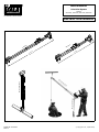
Pole Hoist System
Models:
8510409, 8510476, 8511235, 8516442
6-10 ft
(1.8-3.0 m)
8510476
4-7 ft
(1.2-2.1 m)
8510409
8511235/8516442
851409/8510476
8511235/8516442

2
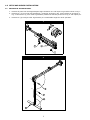
1.0 SETUP AND WINCH INSTALLATION
1.1 SETTING UP THE POLE HOIST
1. Remove all parts from strorage/transport bags containers etc. and layout on ground as shown in Fig. 1.
2. Remove Pin (1) from T-bar leg assembly(2), rotate leg as shown in Fig. 2 and replace pin as shown in
Fig. 2. Remove Pin (3) from T-bar leg assembly rotate foot assembly as shown in Fig. 2 and replace pin.
3. Remove Pin (4) to adjust T-bar leg assembly to a comfortable height for winch operation.
1
2
1
4
2
3

3
3
4
4
2
1
3
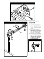
1.2 WINCH & CABLE ROUTING
INSTALLATION
1. Install winch.
2. Pay out 5’ to 10’ of cable from
winch, maintaining at least 10
lb. (5 kg) of tension on cable at
all times. (Please refer to winch
manual.)
3. Remove cable roller pin (1) &
guide pulley (2) from pole hoist
mast assembly (3). Place cable
under guide pulley and replace
guide pulley & cable roller pin.
4. Rotate pole hoist head assembly
(4) so that slots through head
align. Place cable through slot in
head assembly and over pulley
and around cable retainer spring
(5). See Fig. 5 for cable path
through head assembly.
5
5
Cable Path

4
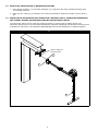
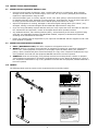
1.3 POLE HOIST INSTALLATION TO RATED ANCHOR POINT
1. Using hanger bracket (1) on top pulley assembly (2), hang pole hoist using certifi ed anchorage point
and certifi ed hardware.
2. Make sure the T-bar leg (3) assembly is as vertical as possible to support the weight of winch while in
use.
1.4 INSTALLATION OF WINCHES, SELF-RETRACTING LIFELINES ( SRL’S), WORK POSITIONING AND
FALL-ARREST DEVICES NOT MANUFACTURED BY CAPITAL SAFETY GROUP
Your Pole-Hoist system can be used as a support structure for various types of safety devices. Any
accessories being used for the hoist MUST BE installed, inspected, maintained and operated according to the
manufactures instructions. All installations MUST BE approved to local standards by a qualifi ed engineer.
6
1
2
2
Engineer Approved
Anchorage Point

5
2.0 OPERATION
WARNING: The Pole Hoist System is designed to attach to a person (entrant) and allow them to enter a confi ned space and assist
in exiting if required. Every new operator must read, understand, and follow the instructions in this manual. No one should be allowed to
use the equipment without training. The training should be reviewed with experienced operators on a regular basis. At regular intervals,
perform a detailed inspection of the equipment and document the results. Remove this system from service if any defi ciencies are found.
Alterations or misuse of this equipment, or the failure to follow the instruction, may result in serious injury or death.
2.1 OPERATING SAFETY: Many of the features incorporated into this equipment are a result of suggestions
made by customers like you. Read this manual carefully to learn how to operate the equipment safely and
set it to perform as intended. By following the operating instruction in conjunction with a good maintenance
program, your equipment will provide many years of trouble-free service:
• Read, understand and follow these instructions and labels on the equipment before using, maintaining or
inspecting the equipment.
• Train all operators before allowing them to use the equipment. An untrained operator exposes
themselves, bystanders, and workers to possible serious injury or death.
• Visually inspect the equipment and all auxiliary components and equipment before using. Correct any
problems before using the equipment.
• Securely anchor the winch before using, where applicable.
• Use only certifi ed anchor and connector components in your system.
• All anchor points or mounting/setup locations for permanent or portable systems must be approved to
local standards by a qualifi ed engineer.
• Use only an approved full body harness for your workers.
• Always work in teams. One person works in the confi ned space and the other pays out the line and reels
it in.
• Do not use the winch when the brake wear indicator displays in the red or the counter exceeds 30,000
cycles or 5 years. Return the winch to the manufacturer for service. (refer to the manufacturer’s
instruction included with the Winch for details on winch operation.)
• Do not exceed 450 lbs. (205 kg) on the line during operation.
• Use only retractable lifelines or shock absorbers with a maximum arresting force (MAF) equal to or lower
than the lowest rated component of your system.
• Establish a regular training program for new & experienced workers.
• Establish a detailed inspection program for your equipment and document the fi ndings. Return the
equipment to the manufacturer for rework if any problems are found.
• Plan your work program before starting. Have the required people, equipment and procedures available
to do the job.
• Do not use the equipment around physical or environmental hazards. This list includes, but is not limited
to:
1. Corrosion that may affect the structural integrity of the lifeline or other components. b] chemicals
which may degrade components and may not be visible.
2. Toxic Gases: Rescuers and/or workers can be killed in toxic environments.
3. Heat or elevated temperatures.
4. Moving Machinery: Workers or auxiliary equipment can be contacted by or pulled into moving
components.
5. Sharp Edges: Workers or equipment can be injured or damaged by sharp edges or components.
6. Electrical hazards: stay away from power lines or components carrying electrical power.
7. Overload: Do not exceed 450 lbs. (205 kg.) during operation.
8. Follow all confi ned space regulations in the respective standards.
9. Noise: Wear appropriate noise protection where necessary
10. Environmental Hazards: Do not operate equipment during an electrical storm.

6
3.0 INSPECTION & MAINTENANCE
3.1 INSPECTION OF EQUIPMENT PRIOR TO USE:
• Check all structural parts for damage: dents, cracked welds bend or crushed tubes. Minor cosmetic
damage will not affect the structural integrity of the hoist, but any seriously damaged parts MUST BE
repaired or replaced before using the hoist.
• Check all hardware (pins, tri-screws, adjuster screws, nuts, bolts, pulleys, rollers and winch brackets)
for damaged threads, bend, damaged or missing fasteners, loose fasteners. Check all pulleys and rollers
for chips, grooves and excessive wear. Ensure that all pulleys and rollers turn freely.
• Inspect all equipment for missing, damaged or otherwise illegible warning labels (see “Labels”). Any
damaged, missing or otherwise illegible stickers MUST BE replaced before using hoist.
• If you are using CSG Safety Systems Winches with your hoist, inspect the winch and cable as outlined in
the “maintenance and inspection” section of the Digital Series Winch operators manual.
• Any additional winches, self-retracting lifelines (SRLs), work positioning or fall-arrest equipment being
used with your CSG Safety Systems Hoist MUST BE installed, inspected, maintained and operated
according to the manufactures instruction.
• Report any problems with the equipment to your supervisor and DO NOT USE the equipment until it has
been repaired or replaced.
3.2 INSPECTION/MAINTENANCE SCHEDULE:
• DAILY ( BEFORE EACH USE): See above “Inspection of Equipment Prior to Use”.
• WEEKLY: Perform a complete visual inspection of equipment as outlined in “Inspection of Equipment
Prior to Use”. Clean equipment as required, to thoroughly inspect all welds, labels, pins, fasteners,
pulleys, rollers, brackets and parts. Record all fi ndings on a copy of the “Inspection & Maintenance Log”.
If any problems are found with the equipment DO NOT USE until it has been repaired.
• ANNUALLY: Clean unit thoroughly, using a damp cloth and a mild soap solution. Perform a complete
visual inspection as described in “Inspection of Equipment Prior to Use” Record all fi ndings on a copy of
the “Inspection & Maintenance Log”. If any problems are found with the equipment, DO NOT USE until it
has been repaired.
4.0 LABELS
The following labels must be present on the equipment and must be fully legible:
A
B
A
C
A
B
8513219 Rev. B
AVERTISSEMENT
WARNING
This component is rated for a working load of 450 lb. (205 kg).
Retractable devices or shock absorbers must have a MAXIMUM
ARRESTING FORCE (M.A.F.) RATING OF 900 lb. (4kN) OR LESS.
System rating is that of the lowest rated system component.
Cet élément est conçu pour une charge de travail de 205 kg
(450 lb). Des systèmes rétractables ou des amortisseurs de choc
doivent avoir une FORCE D'ARRÊT MAXIMALE (Maximum Arrest
Force, M.A.F.) NOMINALE DE 4 kN (900 lb) OU MOINS. La
composant de la plus basse catégorie dans le système.
C
WARNING
8516420 REV B
THIS IS NOT A STRUCTURALLY
RATED LOAD BEARING
COMPONENT. DO NOT USE IN
PLACE OF LOAD BEARING
COMPONENTS.

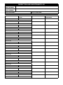
INSPECTION AND MAINTENANCE LOG
SERIAL NUMBER:
MODEL NUMBER:
DATE PURCHASED: DATE OF FIRST USE:
INSPECTION DATE INSPECTION ITEMS
NOTED
CORRECTIVE ACTION MAINTENANCE
PERFORMED
Approved By:
Approved By:
Approved By:
Approved By:
Approved By:
Approved By:
Approved By:
Approved By:
Approved By:
Approved By:
Approved By:
Approved By:
Approved By:
Approved By:
Approved By:
Approved By:
Approved By:
Approved By:

LIMITED LIFETIME WARRANTY
Warranty to End User: D B Industries, Inc., dba CAPITAL SAFETY USA (“CAPITAL SAFETY”) warrants to the
original end user (“End User”) that its products are free from defects in materials and workmanship under
normal use and service. This warranty extends for the lifetime of the product from the date the product is
purchased by the End User, in new and unused condition, from a CAPITAL SAFETY authorized distributor.
CAPITAL SAFETY’S entire liability to End User and End User’s exclusive remedy under this warranty is limited
to the repair or replacement in kind of any defective product within its lifetime (as CAPITAL SAFETY in its sole
discretion determines and deems appropriate). No oral or written information or advice given by CAPITAL
SAFETY, its distributors, directors, offi cers, agents or employees shall create any different or additional
warranties or in any way increase the scope of this warranty. CAPITAL SAFETY will not accept liability for defects
that are the result of product abuse, misuse, alteration or modifi cation, or for defects that are due to a failure to
install, maintain, or use the product in accordance with the manufacturer’s instructions.
CAPITAL SAFETY’S WARRANTY APPLIES ONLY TO THE END USER. THIS WARRANTY IS THE ONLY WARRANTY
APPLICABLE TO OUR PRODUCTS AND IS IN LIEU OF ALL OTHER WARRANTIES AND LIABILITIES, EXPRESSED
OR IMPLIED. CAPITAL SAFETY EXPRESSLY EXCLUDES AND DISCLAIMS ANY IMPLIED WARRANTIES OF
MERCHANTABILITY OR FITNESS FOR A PARTICULAR PURPOSE, AND SHALL NOT BE LIABLE FOR INCIDENTAL,
PUNITIVE OR CONSEQUENTIAL DAMAGES OF ANY NATURE, INCLUDING WITHOUT LIMITATION, LOST PROFITS,
REVENUES, OR PRODUCTIVITY, OR FOR BODILY INJURY OR DEATH OR LOSS OR DAMAGE TO PROPERTY, UNDER
ANY THEORY OF LIABILITY, INCLUDING WITHOUT LIMITATION, CONTRACT, WARRANTY, STRICT LIABILITY, TORT
(INCLUDING NEGLIGENCE) OR OTHER LEGAL OR EQUITABLE THEORY.
ISO
9001
CSG USA & Latin America
3833 SALA Way
Red Wing, MN 55066-5005
Toll Free: 800.328.6146
Phone: 651.388.8282
Fax: 651.388.5065
solutions@capitalsafety.com
CSG Canada
260 Export Boulevard
Mississauga, ON L5S 1Y9
Phone: 905.795.9333
Toll-Free: 800.387.7484
Fax: 888.387.7484
info.ca@capitalsafety.com
CSG Northern Europe
5a Merse Road
North Moons, Moat
Reditch, Worcestershire, UK
B98 9HL
Phone: + 44 (0)1527 548 000
Fax: + 44 (0)1527 591 000
csgne@capitalsafety.com
CSG EMEA
(Europe, Middle East, Africa)
Le Broc Center
Z.I. 1ère Avenue
5600 M B.P. 15 06511
Carros
Le Broc Cedex
France
Phone: + 33 4 97 10 00 10
Fax: + 33 4 93 08 79 70
information@capitalsafety.com
CSG Australia & New Zealand
95 Derby Street
Silverwater
Sydney NSW 2128
AUSTRALIA
Phone: +(61) 2 8753 7600
Toll-Free : 1 800 245 002 (AUS)
Toll-Free : 0800 212 505 (NZ)
Fax: +(61) 2 87853 7603
sales@capitalsafety.com.au
CSG Asia
Singapore:
16S, Enterprise Road
Singapore 627666
Phone: +65 - 65587758
Fax: +65 - 65587058
inquiry@capitalsafety.com
Shanghai:
Rm 1406, China Venturetech Plaza
819 Nan Jing Xi Rd,
Shanghai 200041, P R China
Phone: +86 21 62539050
Fax: +86 21 62539060
www.capitalsafety.com
The Ultimate in Fall Protection
-
 1
1
-
 2
2
-
 3
3
-
 4
4
-
 5
5
-
 6
6
-
 7
7
-
 8
8


3M 8530252 Manuel utilisateur
- Taper
- Manuel utilisateur
- Ce manuel convient également à
dans d''autres langues
- English: 3M 8530252 User manual
Documents connexes
-
3M DBI-SALA® Confined Space Adjustable Offset Upper Davit Mast 8518006, 1 EA Mode d'emploi
-
-
-
-
-
-
-
-
3M DBI-SALA® Lad-Saf™ Stainless Steel Cable Lifeline, 1x7 6152100, 1 EA Mode d'emploi
-
3M DBI-SALA® Railok 90™ Extruded Rail 6000031, 1 EA Mode d'emploi