Tripp Lite N785-I01-SFP-DU Mode d'emploi
- Catégorie
- Convertisseurs de média réseau
- Taper
- Mode d'emploi

1
Industrial Gigabit Copper to
Fiber Media Converter,
Unmanaged, RJ45/SFP
Model: N785-I01-SFP-DU
1111 W. 35th Street, Chicago, IL 60609 USA • tripplite.com/support
Copyright © 2021 Tripp Lite. All rights reserved.
Quick Start Guide
WARRANTY REGISTRATION
Register your product today and be
automatically entered to win an ISOBAR®
surge protector in our monthly drawing!
tripplite.com/warranty
Español 13 • Français 25
21-07-116 93-3F8F.indb 121-07-116 93-3F8F.indb 1 11/29/2021 3:14:58 PM11/29/2021 3:14:58 PM

2
• Extends a Gigabit Ethernet connection to an open SFP port
with no software or additional configuration
• Industrial housing withstands a wide range of operating
temperatures from -40° to 75°C
• Provides ESD, RFI and surge protection
• IP30 rating guarantees protection from tools and wires
greater than 2.5 mm
• Open SFP port works with a variety of SFP transceivers
• Can be powered using the included terminal block or a
user-provided 12V DC power adapter
• Auto MDI/MDI-X functionality removes the need for
crossover cabling
Product Features
Package Contents
• N785-I01-SFP-DU Media Converter
• Terminal Block (20~57VDC)
• DIN Rail Kit
• RJ45 Cap
• SFP Cap
• Quick Start Guide
21-07-116 93-3F8F.indb 221-07-116 93-3F8F.indb 2 11/29/2021 3:14:58 PM11/29/2021 3:14:58 PM

3
Optional Accessories
• N001-Series Cat5e Snagless Ethernet Cables
• N201-Series Cat6 Snagless Ethernet Cables
• N286-Series Transceivers
21-07-116 93-3F8F.indb 321-07-116 93-3F8F.indb 3 11/29/2021 3:14:58 PM11/29/2021 3:14:58 PM

4
Installation
1. Optional: Connect the included DIN Rail Kit to the unit
using the included mounting hardware.
2. Connect the RJ45 port of an unmanaged copper Ethernet
switch to the RJ45 port of the first N785-I01-SFP-DU
media converter with a user-supplied Cat5e/6 cable.
3. Connect a transceiver to the first media converter’s open
SFP port.
4. Connect fiber cabling matching the transceiver type between
the transceiver’s port and a matching transceiver connected
to a second N785-I01-SFP-DU media converter.
Copper to Copper Installation
Notes:
• The following installation instructions refer to an installation in which
two media converters are used to increase the maximum distance
between two copper switches.
• To effectively communicate between media converters, the speeds of
the copper and fiber ports of each media converter should be identical.
The diagram and table below show the speed you should use between
media converters and switches, as well as which LED will illuminate
with respect to that speed.
N785-101-SFP-DU N785-101-SFP-DUEthernet copper switch 1
100/1000M/Auto 100/1000M/Auto
Ethernet copper switch 2
Copper Copper
Fiber
100/1000M
21-07-116 93-3F8F.indb 421-07-116 93-3F8F.indb 4 11/29/2021 3:14:58 PM11/29/2021 3:14:58 PM

5
Installation
5. Connect the RJ45 port of a second unmanaged copper
Ethernet switch to the RJ45 port of the second
N785-I01-SFP-DU media converter with a user-supplied
Cat5e/6 cable.
6. Connect the 12~57VDC terminal block or optional
12V DC power supply to the media converters, and plug
them into an available wall outlet, Uninterruptible Power
Supply (UPS) or Power Distribution Unit (PDU).
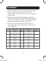
7. When all connections have been made, check the
“L/A (Link/Activity)” LED to confirm the connection has
been established.
Item Copper Switch
#1 Setting
SFP
Type
Copper Switch #2
Setting
LED
Displayed
1 Auto
(100/1000 Mbps) GbE Auto
(100/1000 Mbps) 1000
2 Auto
(100/1000 Mbps) FX Auto
(100/1000 Mbps) 100
3 Auto
(100 Mbps) FX Auto
(100 Mbps) 100
4 1G
(Force) GbE 1G
(Force) 1000
5 100F
(Force) FX 100F
(Force) 100
6 100H
(Force) FX 100H
(Force) 100
21-07-116 93-3F8F.indb 521-07-116 93-3F8F.indb 5 11/29/2021 3:14:59 PM11/29/2021 3:14:59 PM

6
Installation
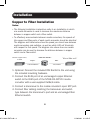
Copper to Fiber Installation
Notes:
• The following installation instructions refer to an installation in which
one media converter is used to increase the maximum distance
between a copper switch and a fiber switch.
• To effectively communicate between media converters, the speeds of
the copper and fiber ports of each media converter should be identical.
The diagram and table below show the speed you should use between
media converters and switches, as well as which LED will illuminate
with respect to that speed. The diagram also shows how one media
converter can be used to increase the distance between a copper
switch and a fiber switch.
1. Optional: Connect the included DIN Rail Kit to the unit using
the included mounting hardware.
2. Connect the RJ45 port of an unmanaged copper Ethernet
switch to the RJ45 port of the N785-I01-SFP-DU media
converter with a user-supplied Cat5e/6 cable.
3. Connect a transceiver to the media converter’s open SFP port.
4. Connect fiber cabling matching the transceiver and switch
type between the transceiver’s port and an unmanaged fiber
Ethernet switch.
N785-101-SFP-DU
100/1000M/Auto
Ethernet FIBER switch
Copper Fiber
100/1000M
Ethernet copper switch/
IP-CAM
21-07-116 93-3F8F.indb 621-07-116 93-3F8F.indb 6 11/29/2021 3:14:59 PM11/29/2021 3:14:59 PM

7
Installation
5. Connect the 12~57VDC terminal block or optional 12V DC
power supply to the media converter, and plug it into an
available wall outlet, Uninterruptible Power Supply (UPS) or
Power Distribution Unit (PDU).
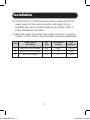
6. When all connections have been made, check the “L/A (Link/
Activity)” LED to confirm the connection has been established.
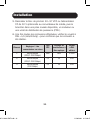
Item Copper Switch
#1 Setting
SFP
Type
Fiber Switch
Setting
LED
Displayed
1 Auto (100/1000 Mbps) GbE GbE 1000
2 Auto (100/1000 Mbps) FX FX 100
3 Auto (100 Mbps) FX FX 100
21-07-116 93-3F8F.indb 721-07-116 93-3F8F.indb 7 11/29/2021 3:14:59 PM11/29/2021 3:14:59 PM

8
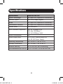
Specifications
Specification N785-I01-SFP-DU
Optical Wavelength N/A (Open SFP, depends on transceiver)
Network Speed 100/1000 Mbps (Gigabit)
Mode N/A (Open SFP, depends on transceiver)
Transmission Distance N/A (Open SFP, depends on transceiver)
Duplex Mode Auto MDI/MDI-X
IEEE Standards Supported 802.3u 100Base-TX/FX
802.3ab 1000Base-T
802.3z 1000Base-SX/LX
Power Consumption 6W
Power Supply Input 12~57VDC (Terminal Block) or
12V DC (DC Power Supply)
Operating Temperature -40° to 167°F (-40° to 75°C)
Storage Temperature -40° to 185°F (-40° to 85°C)
Relative Humidity 5% to 95% RH, Non-Condensing
Unit Dimensions (H x W x D)
2 x 1.7 x 2.4 in. / 5 x 4.25 x 6.1 cm
21-07-116 93-3F8F.indb 821-07-116 93-3F8F.indb 8 11/29/2021 3:14:59 PM11/29/2021 3:14:59 PM

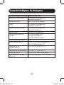
9
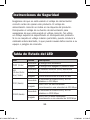
Safety Instructions
LED Status Table
LED Status Description
PWR (Green) On Power is on
Off Power is off or experiencing failure
L/A
(Link/Activity, Green)
On Ethernet (RJ45) link is up
Blinking Activity (transmitting/receiving data)
Off Port disconnected or link failed
100 (Green)
On Both RJ45 and SFP link speed set
at 100 Mbps
Off Either RJ45 or SFP is not linked
correctly at 100 Mbps speed
1000 (Green)
On Both RJ45 and SFP link speed set
at 1000 Mbps
Off Either RJ45 or SFP is not linked
correctly at 1000 Mbps speed
Ensure the correct power voltage is being used before operating
this product. The correct power supply voltage is listed on
the product label. Check the voltage of your power source to
make sure that you are using the correct voltage. Do not use
a voltage greater than what is specified on the product label.
Failing to adhere to the maximum allowable voltage can lead
to overheating wiring, which can cause serious damage to your
equipment or fire hazards.
21-07-116 93-3F8F.indb 921-07-116 93-3F8F.indb 9 11/29/2021 3:14:59 PM11/29/2021 3:14:59 PM

10
Warranty and Product Registration
2-Year Limited Warranty
Seller warrants this product, if used in accordance with all applicable instructions,
to be free from original defects in material and workmanship for a period of two
(2) years from the date of initial purchase. If the product should prove defective
in material or workmanship within that period, Seller will repair or replace the
product, at its sole discretion.
THIS WARRANTY DOES NOT APPLY TO NORMAL WEAR OR TO DAMAGE
RESULTING FROM ACCIDENT, MISUSE, ABUSE OR NEGLECT. SELLER
MAKES NO EXPRESS WARRANTIES OTHER THAN THE WARRANTY
EXPRESSLY SET FORTH HEREIN. EXCEPT TO THE EXTENT PROHIBITED
BY APPLICABLE LAW, ALL IMPLIED WARRANTIES, INCLUDING ALL
WARRANTIES OF MERCHANTABILITY OR FITNESS, ARE LIMITED IN
DURATION TO THE WARRANTY PERIOD SET FORTH ABOVE; AND
THIS WARRANTY EXPRESSLY EXCLUDES ALL INCIDENTAL AND
CONSEQUENTIAL DAMAGES. (Some states do not allow limitations on how
long an implied warranty lasts, and some states do not allow the exclusion or
limitation of incidental or consequential damages, so the above limitations or
exclusions may not apply to you. This warranty gives you specic legal rights,
and you may have other rights which vary from jurisdiction to jurisdiction.)
WARNING: The individual user should take care to determine prior to use
whether this device is suitable, adequate or safe for the use intended. Since
individual applications are subject to great variation, the manufacturer makes no
representation or warranty as to the suitability or tness of these devices for any
specic application.
Product Registration
Visit tripplite.com/warranty today to register your new Tripp Lite product. You’ll be
automatically entered into a drawing for a chance to win a FREE Tripp Lite product!*
*No purchase necessary. Void where prohibited. Some restrictions apply. See website for details.
21-07-116 93-3F8F.indb 1021-07-116 93-3F8F.indb 10 11/29/2021 3:14:59 PM11/29/2021 3:14:59 PM

11
Warranty and Product Registration
WEEE Compliance Information for Tripp Lite Customers
and Recyclers (European Union)
Under the Waste Electrical and Electronic Equipment (WEEE) Directive
and implementing regulations, when customers buy new electrical and
electronic equipment from Tripp Lite, they are entitled to:
• Send old equipment for recycling on a one-for-one, like-for-like basis
(this varies depending on the country)
• Send the new equipment back for recycling when this ultimately
becomes waste
Use of this equipment in life support applications where failure of this equipment
can reasonably be expected to cause the failure of the life support equipment or
to signicantly aect its safety or eectiveness is not recommended.
Tripp Lite has a policy of continuous improvement. Specications are subject to
change without notice. Photos and illustrations may dier slightly from actual products.
21-07-116 93-3F8F.indb 1121-07-116 93-3F8F.indb 11 11/29/2021 3:14:59 PM11/29/2021 3:14:59 PM

12
1111 W. 35th Street, Chicago, IL 60609 USA • tripplite.com/support
21-07-116 • 93-3F8F_RevA
21-07-116 93-3F8F.indb 1221-07-116 93-3F8F.indb 12 11/29/2021 3:14:59 PM11/29/2021 3:14:59 PM

13
Convertidor de Medios
Industrial Gigabit de Cobre
a Fibra, No Administrado,
RJ45/SFP
Modelo: N785-I01-SFP-DU
1111 W. 35th Street, Chicago, IL 60609, EE. UU. • tripplite.com/support
Copyright © 2021 Tripp Lite. Todos los derechos reservados.
Guía de Inicio Rápido
English 1 • Français 25
21-07-116 93-3F8F.indb 1321-07-116 93-3F8F.indb 13 11/29/2021 3:14:59 PM11/29/2021 3:14:59 PM

14
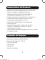
• Extiende una conexión Gigabit Ethernet a un puerto SFP
abierto sin software ni configuración adicional
• El gabinete industrial soporta una amplia gama de
temperaturas de operación de -40 °C a 75 °C
• Proporciona protección contra ESD, RFI y sobretensiones
• La especificación IP30 garantiza protección contra
herramientas y cables superior a 2.5 mm
• El puerto SFP abierto trabaja con una variedad de
transceptores SFP
• Puede alimentarse usando el bloque de terminales
incluido o un adaptador de corriente de 12V CD
suministrado por el usuario
• La funcionalidad automática MDI/MDI-X elimina la necesidad
de cableado cruzado
Características del Producto
Contenido del Empaque
• Convertidor de Medios N785-I01-SFP-DU
• Bloque de Terminales (20~57V CD)
• Juego para Riel DIN
• Tapa de RJ45
• Tapa de SFP
• Guía de Inicio Rápido
21-07-116 93-3F8F.indb 1421-07-116 93-3F8F.indb 14 11/29/2021 3:14:59 PM11/29/2021 3:14:59 PM

15
Accesorios Opcionales
• Cables Ethernet Snagless Cat5e Serie N001
• Cables Ethernet Snagless Cat6 de la Serie N201
• Transceptores de la Serie N286
21-07-116 93-3F8F.indb 1521-07-116 93-3F8F.indb 15 11/29/2021 3:14:59 PM11/29/2021 3:14:59 PM

16
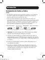
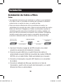
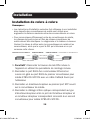
Instalación
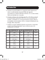
1. Opcional: Conecte el juego de riel DIN incluido a la unidad
usando los accesorios de instalación incluidos.
2. Conecte el puerto RJ45 de un switch Ethernet de cobre no
administrado al puerto RJ45 del primer convertidor de medios
N785-I01-SFP-DU con un cable Cat5e / Cat6 suministrado por
el usuario.
3. Conecte un transceptor al primer puerto SFP abierto en el
convertidor de medios.
4. Conecte el cableado de fibra que coincida con el tipo de
transceptor entre el puerto del transceptor y un transceptor
correspondiente conectado a un segundo convertidor de
medios N785-I01-SFP-DU.
Instalación de Cobre a Cobre
Notas:
• Las siguientes instrucciones de instalación se refieren a una instalación
en la que se utilizan dos convertidores de medios para aumentar la
distancia máxima entre dos switches de cobre.
• Para comunicarse eficazmente entre convertidores de medios, las
velocidades de los puertos de cobre y fibra de cada convertidor de medios
deben ser idénticas. El diagrama y la tabla a continuación muestran la
velocidad que debe usar entre convertidores de medios y switches, así
como qué LED se encenderá con respecto a esa velocidad.
N785-101-SFP-DU N785-101-SFP-DUSwitch de cobre Ethernet 1
100/1000M/Auto 100/1000M/Auto
Switch de cobre Ethernet 2
Cobre Cobre
Fibra
100/1000M
21-07-116 93-3F8F.indb 1621-07-116 93-3F8F.indb 16 11/29/2021 3:14:59 PM11/29/2021 3:14:59 PM

17
Instalación
5. Conecte el puerto RJ45 de un segundo switch Ethernet de
cobre no administrado al puerto RJ45 del segundo
convertidor de medios N785-I01-SFP-DU con un cable Cat5e /
Cat6 suministrado por el usuario.
6. Conecte el bloque de terminales de 12V~57V CD o la fuente
de alimentación opcional de 12V CD a los convertidores de
medios y enchúfelos en un tomacorriente de pared, sistema
de respaldo ininterrumpible (UPS) o Unidad de Distribución de
Energía (PDU) disponible.
7. Cuando se hayan realizado todas las conexiones, compruebe
el LED "L/A (Enlace/Actividad)" para confirmar que se ha
establecido la conexión.
Ítem Configuración del
Switch de Cobre #1
Tipo
de SFP
Configuración del
Switch de Cobre #2
LED
Mostrado
1 Auto
(100/1000 Mbps)
GbE Auto
(100/1000 Mbps)
1000
2 Auto
(100/1000 Mbps)
FX Auto
(100/1000 Mbps)
100
3 Auto
(100 Mbps)
FX Auto
(100 Mbps)
100
4 1G
(Fuerza)
GbE 1G
(Fuerza)
1000
5 100F
(Fuerza)
FX 100F
(Fuerza)
100
6 100H
(Fuerza)
FX 100H
(Fuerza)
100
21-07-116 93-3F8F.indb 1721-07-116 93-3F8F.indb 17 11/29/2021 3:14:59 PM11/29/2021 3:14:59 PM

18
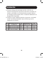
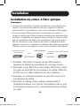
Instalación
Instalación de Cobre a Fibra
Notas:
• Las siguientes instrucciones de instalación se refieren a una instalación
en la que se usa un convertidor de medios para aumentar la distancia
máxima entre un switch de cobre y un switch de fibra.
• Para comunicarse eficazmente entre convertidores de medios, las
velocidades de los puertos de cobre y fibra de cada convertidor de medios
deben ser idénticas. El diagrama y la tabla a continuación muestran la
velocidad que debe usar entre convertidores de medios y switches, así
como qué LED se encenderá con respecto a esa velocidad. El diagrama
también muestra cómo puede usarse un convertidor de medios para
aumentar la distancia entre un switch de cobre y un switch de fibra.
1. Opcional: Conecte el juego de riel DIN incluido a la unidad
usando los accesorios de instalación incluidos.
2. Conecte el puerto RJ45 de un switch Ethernet de cobre no
administrado al puerto RJ45 del convertidor de medios N785-I01-
SFP-DU con un cable Cat5e / Cat6 suministrado por el usuario.
3. Conecte un transceptor al puerto SFP abierto en el convertidor
de medios.
4. Conecte el cableado de fibra que coincida con el tipo de
transceptor y switch entre el puerto del transceptor y un switch
Ethernet de fibra no administrado.
N785-101-SFP-DU
100/1000M/Auto
Switch de FIBRA
Ethernet
Cobre Fibra
100/1000M
Switch de cobre
Ethernet/IP-CAM
21-07-116 93-3F8F.indb 1821-07-116 93-3F8F.indb 18 11/29/2021 3:14:59 PM11/29/2021 3:14:59 PM

19
Instalación
5. Conecte el bloque de terminales de 12V~57V CD o la
fuente de alimentación opcional de 12V CD al convertidor de
medios y enchúfela en un tomacorriente de pared, sistema
de respaldo ininterrumpible (UPS) o Unidad de Distribución de
Energía (PDU) disponible.
6. Cuando se hayan realizado todas las conexiones, compruebe
el LED "L/A (Enlace/Actividad)" para confirmar que se ha
establecido la conexión.
Ítem Configuración del Switch
de Cobre #1
Tipo
de SFP
Configuración del
Switch de Fibra
LED
Mostrado
1 Auto (100/1000 Mbps) GbE GbE 1000
2 Auto (100/1000 Mbps) FX FX 100
3 Auto (100 Mbps) FX FX 100
21-07-116 93-3F8F.indb 1921-07-116 93-3F8F.indb 19 11/29/2021 3:15:00 PM11/29/2021 3:15:00 PM

20
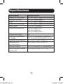
Especificaciones
Especificación N785-I01-SFP-DU
Longitud de Onda Óptica N/A (SFP abierto, depende del transceptor)
Velocidad de la Red 100/1000 Mbps (Gigabit)
Modo N/A (SFP abierto, depende del transceptor)
Distancia de Transmisión N/A (SFP abierto, depende del transceptor)
Modo Dúplex MDI / MDI-X automático
Permite Estándares IEEE 802.3u 100Base-TX/FX
802.3ab 1000Base-T
802.3z 1000Base-SX/LX
Consumo de Energía 6W
Entrada de Alimentación
de Energía
12~57V CD (Bloque de Terminales) o
12V CD (Fuente de Alimentación de CD)
Temperatura de Operación -40 °C a 75 °C [-40 °F a 167 °F]
Temperatura de
Almacenamiento
-40 °C a 85 °C [-40 °F a 185 °F]
Humedad Relativa De 5% a 95% de HR, Sin Condensación
Dimensiones de la Unidad
(Al x An x Pr)
5 x 4.25 x 6.1 cm [2" x 1.7" x 2.4"]
21-07-116 93-3F8F.indb 2021-07-116 93-3F8F.indb 20 11/29/2021 3:15:00 PM11/29/2021 3:15:00 PM
La page est en cours de chargement...
La page est en cours de chargement...
La page est en cours de chargement...
La page est en cours de chargement...
La page est en cours de chargement...
La page est en cours de chargement...
La page est en cours de chargement...
La page est en cours de chargement...
La page est en cours de chargement...
La page est en cours de chargement...
La page est en cours de chargement...
La page est en cours de chargement...
La page est en cours de chargement...
La page est en cours de chargement...
La page est en cours de chargement...
La page est en cours de chargement...
-
 1
1
-
 2
2
-
 3
3
-
 4
4
-
 5
5
-
 6
6
-
 7
7
-
 8
8
-
 9
9
-
 10
10
-
 11
11
-
 12
12
-
 13
13
-
 14
14
-
 15
15
-
 16
16
-
 17
17
-
 18
18
-
 19
19
-
 20
20
-
 21
21
-
 22
22
-
 23
23
-
 24
24
-
 25
25
-
 26
26
-
 27
27
-
 28
28
-
 29
29
-
 30
30
-
 31
31
-
 32
32
-
 33
33
-
 34
34
-
 35
35
-
 36
36


Tripp Lite N785-I01-SFP-DU Mode d'emploi
- Catégorie
- Convertisseurs de média réseau
- Taper
- Mode d'emploi
dans d''autres langues
Documents connexes
-
Tripp Lite Gigabit Fiber to Ethernet Media Converters Le manuel du propriétaire
-
Tripp Lite N785-INT-SC-SM Le manuel du propriétaire
-
-
-