
1
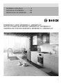
DOWNDRAFT HOOD HDD80051UC, HDD86051UC
HOTTE À TIRAGE DESCENDANT HDD80051UC, HDD86051UC
CAMPANA DE TIRO DESCENDENTE HDD80051UC, HDD86151UC
Installation instructions ................. 2
Instructions d’installation ............ 23
Instrucciones de instalación ....... 44

English 2
ABOUT THIS MANUAL ................................................. 3
Be sure to observe all listed warnings and cautions....... 3
IMPORTANT SAFETY INSTRUCTIONS ....................4-7
General notes ................................................................. 4
Proper installation and maintenance .............................. 5
Fire safety ....................................................................... 6
Child safety ..................................................................... 7
State of California Proposition 65 Warnings ................... 7
Protecting the environment............................................. 7
BEFORE YOU BEGIN .................................................. 8
Installation review .......................................................... 8
Tools needed ................................................................. 8
Parts supplied ................................................................ 8
PLAN THE INSTALLATION .......................................... 9
Select ducting option ...................................................... 9
Ductwork preparation ..................................................... 9
Plan cabinetry ................................................................ 9
DUCT EQUIVALENT CHART ...................................... 10
SYSTEM DIMENSIONS ................................................11
ACCESSORIES ........................................................... 12
INSTALLATION ......................................................13-21
Take measurements .................................................... 13
Cut coutertop opening ................................................. 13
Installation with electric and induction cooktops ........... 13
Installation with gas cooktops ....................................... 14
Prepare downdraft housing .......................................... 14
Optional: Electrical panel can be mounted in a remote
location ......................................................................... 15
A - Installation using fl exible blower attached
to downdraft ................................................................. 15
B - Installation using fl exible or remote blower -
mounted in a remote location - ducting through
front panel opening ...................................................... 16
C - Installation using inline or remote blower - ducting
through left, right, below or rear ................................... 16
Insert upper support brackets and
attach support legs ...................................................... 16
Cut out ductwork opening in cabinet ........................... 17
Mounting downdraft
with recirculation kit (HDDREC5UC) ........................... 17
Mount downdraft in cabinet ....................................17-18
Gas cooktops only: Install gas cooktop seal kit
(HDD0RSP, HDD6RSP) .......................................... 18-19
Install roof cap, wall cap, or remote blower ................. 19
Connect ductwork ........................................................ 19
Install the electrical panel ............................................ 19
Plan house wiring ........................................................ 19
Install electrical wiring .................................................. 20
Plug electrical panel .................................................... 21
Connect downdraft to power ........................................ 21
Install cooking appliance .............................................. 21
Attach endcaps to downdraft ....................................... 21
BOSCH
®
SUPPORT ..................................................... 22
Before calling service ................................................... 22
Data label .................................................................... 22
Service ......................................................................... 22
Parts and accessories .................................................. 22
Additional information on products, accessories,
replacement parts and services can be found at
www.bosch-home.com and in the online shop
www.bosch-home.com/us/store
TABLE OF CONTENTS

English 3
ABOUT THIS MANUAL
Be sure to observe all listed warnings
and cautions.
Look for the triangles with exclamation marks inside.
WARNING
This indicates that death or serious injuries may
occur as a result of non-observance of this warning.
CAUTION
This indicates that minor or moderate injuries may
occur as a result of non-observance of this warning.
NOTICE: This indicates that damage to the appliance or
property may occur as a result of non-compliance with
this advisory.
NOTE: This alerts you to important information and/or
tips.
Pay special attention to the important safety instructions
in the “Safety” section.

English 4
IMPORTANT SAFETY INSTRUCTIONS
READ AND SAVE THESE INSTRUCTIONS
General notes
Examine the appliance after unpacking it. In the event of
transport damage, do not plug it in.
NOTE: Do not remove any of the aluminum tape as it is
needed for sealing air leaks.
WARNING
TO REDUCE THE RISK OF FIRE, ELECTRIC
SHOCK, OR INJURY TO PERSONS, OBSERVE THE
FOLLOWING:
Use this unit only in the manner intended by the
manufacturer. If you have questions, contact the
manufacturer.
Before servicing or cleaning unit, switch power off
at service panel and lock the service disconnecting
means to prevent power from being switched on
accidentally.
When the service disconnecting means cannot be
locked, securely fasten a prominent warning device,
such as a tag, to the service panel.
WARNING
WARNING – TO REDUCE THE RISK OF FIRE,
ELECTRIC SHOCK, OR INJURY TO PERSONS,
OBSERVE THE FOLLOWING:
Installation work and electrical wiring must be
done by qualifi ed person(s) in accordance with all
applicable codes and standards, including fi re-rated
construction.
Suffi cient air is needed for proper combustion and
exhausting of gases through the fl ue (chimney) of fuel
burning equipment to prevent back drafting. Follow the
heating equipment manufacturer’s guideline and safety
standards such as those published by the National
Fire Protection Association (NFPA), and the American
Society for Heating, Refrigeration and Air Conditioning
Engineers (ASHRAE), and the local code authorities.
When cutting or drilling into wall or ceiling, do not
damage electrical wiring and other hidden utilities.
Ducted fans must always be vented to the outdoors.
INSTALLER: LEAVE THESE INSTRUCTIONS
WITH THE APPLIANCE AFTER INSTALLATION IS
COMPLETE.
OWNER: SAVE FOR THE LOCAL INSPECTOR’S USE.
WARNING
When properly cared for, your new appliance has been
designed to be safe and reliable. Read all instructions
carefully before use. These precautions will reduce the
risk of burns, electric shock, fi re, and injury to persons.
When using kitchen appliances, basic safety precautions
must be followed, including those in the following pages.

English 5
Proper installation and maintenance
WARNING
Remove all tape and packaging before using the
appliance. Destroy the packaging after unpacking the
appliance. Never allow children to play with packaging
material.
INSTALLER: Show the owner the location of the circuit
breaker or fuse. Mark it for easy reference.
This appliance must be properly installed and grounded
by a qualifi ed technician. Connect only to properly
grounded outlet. Refer to Installation Instructions for
details.
This appliance is intended for normal family household
use only. It is not approved for outdoor use. See the
Statement of Limited Product Warranty in the Use and
Care Guide. If you have any questions, contact the
manufacturer.
Do not store or use corrosive chemicals, vapors,
fl ammables or nonfood products in or near this appliance.
It is specifi cally designed for use when heating or cooking
food. The use of corrosive chemicals in heating or
cleaning will damage the appliance and could result in
injury.
Do not operate this appliance if it is not working properly,
or if it has been damaged. Contact an authorized servicer.
Do not repair or replace any part of the appliance unless
specifi cally recommended in this manual. Refer all
servicing to a factory authorized service center.
WARNING
Make sure the appliance and lights are cool and power
to the appliance has been turned off before replacing
the LED (if equipped). Failure to do so could result in
electrical shock or burns.
WARNING
Do not use this unit in conjunction with a recirculation unit in
gas cooking application.
CAUTION
Grease left on fi lters can melt and move into the vent and
catch fi re.
WARNING
Hidden surfaces may have sharp edges. Use caution
when reaching behind or under appliance.
WARNING
Unit is heavy and requires at least two people or proper
equipment to move and install.
WARNING
Tie long hair so that it does not hang loose, and do not
wear loose fi tting clothing or hanging garments, such as
ties, scarves, jewelry, or dangling sleeves.
WARNING
When the hood is operated in exhaust-air mode
simultaneously with a different appliance which also
makes use of the same chimney (such as gas, oil or coal-
fi red heaters, continuous-fl ow heaters, hot-water boilers)
care must be taken to ensure that there is an adequate
supply of fresh air which will be needed by the appliance
for combustion.
This can be achieved if combustion air can fl ow through
non-lockable openings, e.g. in doors, windows and via
the air-intake/exhaust-air wall box or by other technical
measures, such as reciprocal interlocking, etc.
WARNING
Avoid carbon monoxide poisoning – Provide adequate air
intake so combustion gases are not drawn back into the room.
An air-intake/exhaust-air wall box by itself is no guarantee
that the limiting value will not be exceeded.
NOTE: When assessing the overall requirement, the
combined ventilation system for the entire household
must be taken into consideration. This rule does not apply
to the use of cooking appliances, such as cooktops and
ovens.
WARNING
To avoid electrical shock hazard, before installing, switch
power off at the service panel and lock the panel to
prevent the power from being switched on accidentally.
IMPORTANT SAFETY INSTRUCTIONS
READ AND SAVE THESE INSTRUCTIONS

English 6
Fire safety
WARNING
Use this appliance only for its intended use as described
in this manual.
Always have a working smoke detector near the kitchen.
In the event that personal clothing or hair catches fi re,
drop and roll immediately to extinguish fl ames.
Have an appropriate fi re extinguisher available, nearby,
highly visible and easily accessible near the appliance.
Smother fl ames from food fi res other than grease fi res
with baking soda. Never use water on cooking fi res.
WARNING
TO REDUCE THE RISK OF INJURY TO PERSONS
IN THE EVENT OF A RANGE TOP GREASE FIRE,
OBSERVE THE FOLLOWING:
a
a. SMOTHER FLAMES with a close-fi tting lid, cookie
sheet, or metal tray, then turn off the burner. BE
CAREFUL TO PREVENT BURNS. If the fl ames do not
go out immediately, EVACUATE AND CALL THE FIRE
DEPARTMENT.
b. NEVER PICK UP A FLAMING PAN – You may be
burned.
c. DO NOT USE WATER, including wet dishcloths or
towels – a violent steam explosion will result.
d. Use an extinguisher ONLY if:
- You know you have a Class ABC extinguisher, and
you already know how to operate it.
- The fi re is small and contained in the area where it
started.
- The fi re department is being called.
- You can fi ght the fi re with your back to an exit.
a
Based on “Kitchen Fire Safety Tips” published by
NFPA.
Whenever possible, do not operate the ventilation system
during a cooktop fi re. However, do not reach through fi re
to turn it off.
Seal the connection points of the ducts appropriately.
Ductwork must vent outside, not into attic spaces for
example, unless the available ’Non-duct Recirculation Kit’
is used.
WARNING
RISK OF FIRE
When gas burners are in operation without any cookware
placed on them, they can build up a lot of heat. A
ventilation appliance installed above the cooker may
become damaged or catch fi re. Only operate the gas
burners with cookware on them.
WARNING
RISK OF FIRE
Hot oil and fat catch fi re fast. Never leave hot oil and fat
unsupervised. Never extinguish a fi re with water. Switch
off the cooking position. Suffocate fl ames carefully with a
lid, a fi re blanket or similar.
WARNING
RISK OF FIRE
Grease deposits in the grease fi lters can ignite.
Clean the grease fi lters at least every two months or as
frequently as necessary. Never operate the appliance
without the grease fi lters.
WARNING
RISK OF FIRE
Grease deposits in the grease fi lters can catch fi re.
Never work with a naked fl ame near the appliance
(e.g. fl ambéing). Install the unit near a heat-producing
appliance for solid fuels (e.g. wood or coal) only if there is
a closed, non-detachable cover. There must be no fl ying
sparks.
WARNING
RISK OF FIRE
Use only metal ductwork.
WARNING
RISK OF BURNS
The accessible parts get hot during operation. Never
touch hot parts. Keep children away.
CAUTION
It is recommended to wear gloves and long sleeves to
protect hands and forearms from abrasion and potential
scratches during the installation process.
IMPORTANT SAFETY INSTRUCTIONS
READ AND SAVE THESE INSTRUCTIONS

English 7
Child safety
When children become old enough to use the appliance,
it is the responsibility of the parents or legal guardians
to ensure that they are instructed in safe practices by
qualifi ed persons.
Do not allow anyone to climb, stand, lean, sit, or hang on
any part of an appliance. This can damage the appliance
or cause injury.
WARNING
Be sure the entire appliance (including the grease fi lters
and light bulbs, if applicable) has cooled and grease
has solidifi ed before attempting to clean any part of the
appliance.
Do not use steam cleaners to clean the appliance.
State of California Proposition 65
Warnings
WARNING
This product may contain a chemical know to the State of
California, which can cause cancer or reproductive harm.
Therefore, the packaging of your product may bear the
following label as required by California:
STATE OF CALIFORNIA PROPOSITION 65 WARNING:
WARNING
Cancer and Reproductive Harm - www.P65Warnings.ca.gov
Protecting the environment
Unpack the appliance and dispose of the packaging in
line with environmental requirements.
NOTICE
Risk of damage due to corrosion. Always turn
appliance on when cooking to avoid condensation
buildup. Condensation can lead to corrosion
damage.
Risk of damage due to moisture entering into the
electronic circuitry. Never clean operator controls with a
wet cloth.
Surface damage due to incorrect cleaning. Clean
stainless steel surfaces in the grain direction only. Do not
use any stainless steel cleaners on operator controls.
Never use strong or abrasive cleaning agents, since they
can cause surface damage.
Risk of damage from condensation back fl ow. Install
exhaust vent at a slight downward slope away from the
appliance (1° slope).
IMPORTANT SAFETY INSTRUCTIONS
READ AND SAVE THESE INSTRUCTIONS

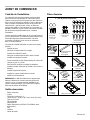
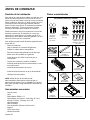
English 8
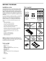
1 Parts Bag containing:
2 - Screws,
1/4-20 x .50
(12.7 mm) Hex
Head
2 - Screws,
no. 8-18 x .375
(9.5 mm) Phillips
8 - Wood Screws,
no. 10 x .50 (12.7 mm)
Phillips Round Head
2 - End Cap Trim
1 - Plastic installation
template
(see page 13) 2 - Support Legs2 - Support Legs
1 - Electrical Panel1 - Electrical Panel
2 - Upper Support 2 - Upper Support
BracketsBrackets
1 - Special key1 - Special key Installation instructionsInstallation instructions Use and Care guide
Wiring diagram
Downdraft Ventilator Housing
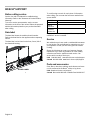
BEFORE YOU BEGIN
Installation review
This downdraft system can be used to exhaust cooking
by-products such as heat, steam, and smoke that may
be created while cooking using gas or electric cooktops.
With its versatile design, there are six (6) basic discharge
options - left, right, rear, front, down and recirculation. It
is important to fi rst plan your installation. The purchase of
additional accessories to complete the installation may be
necessary.
It can be mounted in an island, peninsula, or conventional
wall location. The blower (purchase separately) and
electrical panel can be mounted to the downdraft unit,
inside the cabinet, or in a convenient remote location.
This unit can be easily installed following these basic
steps:
Plan the installation.
Cut out the countertop opening.
Prepare the downdraft housing.
Cut out the cabinet opening for discharge.
Mount the downdraft in the cabinet.
Install gas cooktop seal kit accessory, if applicable.
Connect the ductwork and install the blower.
Install downdraft electrical panel, if in remote
location.
Install the cooking appliance.
Install end caps to downdraft.
Check the operation.
Parts supplied
NOTE: The high level of air fl ow of this appliance may
effect the gas fl ame on some types of gas cooktops. This
is NORMAL and will cause no harm, but can be corrected
by lowering the speed of the blower.
Tools needed
Measuring tape
Pencil
Phillips screwdriver no. 2
Nut drivers - 11/32” (8.7 mm), 3/8” (9.5 mm),
7/16” (11.1 mm)
Box-end wrench
Spirit-level
Aluminum tape (DO NOT use insulating tape)
Saw
Tin snips
Work gloves
Use and care manual
...................2
Manuel d’utilisation et
d’entretien
...................................15
Manual de uso y cuidado............28
DOWNDRAF
T
HOOD HDD80050UC, HDD86050UC
HOTTE À
TIRAGE DESCENDANT HDD80050UC, HDD86050UC
VENTILADOR DE
TIRO DESCENDENTE HDD80050UC, HDD86050UC
DOWNDRAFT HDD80050UC, HDD86050UC
HOTTE ENCASTRÉE HDD80050UC, HDD86050UC
TIRO DESCENDENTE HDD80050UC, HDD86050UC
Installation instructions .................2
Instructions d’installation
............19
Instrucciones de instalación
.......
36

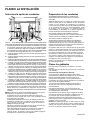
English 9
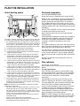
PLAN THE INSTALLATION
NOTE: The manufacturer is not responsible for performance complaints
attributable to the duct section.
The device achieves its optimum performance by means of a short,
straight exhaust air duct and as large a pipe diameter as possible.
The optimum extraction performance is not achieved and fan noise is
increased if exhaust air ducts are long and rough and if there is a large
number of duct bends or diameters less than 6”.
The pipes or hoses for laying the exhaust air line must consist of non-
combustible material.
Seal the connection points of the ducts appropriately.
Ductwork must vent outside, not into attic spaces for example, unless
the available ‘Non-duct Recirculation Kit’ is used.
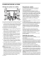
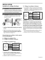
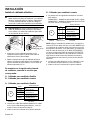
Select ducting option
The 6 basic discharge connections, left, right, rear, front, down and
recirculation can be achieved through A to G with the optional parts listed.
1. The downdraft blower system is designed for use with 8” (203 mm)
round ductwork using a fl exible blower or 6” (152 mm) round ductwork
using an inline or remote blower. (Purchase blowers separately.):
Seven (7) different discharge connections are available - A to G, below:
A = 8” (203 mm) Round, Left Discharge out of Flex Blower
B = 8” (203 mm) Round, Right Discharge out of Flex Blower
C = 8” (203 mm) Round, Down Discharge out of Flex Blower (Electrical
Panel to be mounted remotely)
D = 1-7/8” x 19” (48 mm x 483 mm), Left Discharge out of Housing to
Remote Blower or Flex Blower in remote location. Use 1-7/8” x 19”
(48 mm x 483 mm) to 6” (152 mm) or 8” (203 mm) round transition
or 1-7/8” x 19” (48 mm x 483 mm) ductwork as appropriate.
E = 1-7/8” x 19” (48 mm x 483 mm), Right Discharge out of Housing to
Remote Blower or Flex Blower in remote location. Use 1-7/8” x 19”
(48 mm x 483 mm) to 6” (152 mm) or 8” (203 mm) round transition or
1-7/8” x 19” (48 mm x 483 mm) ductwork as appropriate.
F = 1-7/8” x 19” (48 mm x 483 mm), Rear Discharge out of Housing to
Remote Blower or Flex Blower in remote location. Use 1-7/8” x 19”
(48 mm x 483 mm) to 6” (152 mm) or 8” (203 mm) round transition or
1-7/8” x 19” (48 mm x 483 mm) ductwork as appropriate.
G = 1-7/8” x 19” (48 mm x 483 mm), Down Discharge out of Housing to
Remote Blower or Flex Blower in remote location. Use 1-7/8” x 19”
(48 mm x 483 mm) to 6” (152 mm) or 8” (203 mm) round transition or
1-7/8” x 19” (48 mm x 483 mm) ductwork as appropriate.
2. For best performance: Choose the ducting option which allows the
shortest length of ductwork and a minimum number of elbows and
transitions. Check location of fl oor joists, wall studs, electrical wiring
or plumbing for possible interference.
A
B
C
D
E
F
HD1101
G
Ductwork preparation
DUCTING RECOMMENDATIONS
Proper performance is dependent upon proper ducting.
MAKE-UP AIR: Local building codes may require the use
of make-up air systems when using ducted ventilation
systems greater than specifi ed CFM of air movement.
The specifi ed CFM varies from locale to locale. It is the
responsibility of the owner and the installer to determine if
additional requirements and/or standards apply to specifi c
installations.
DO NOT USE FLEXIBLE DUCT; it creates back pressure/
air turbulence and reduces performance.
Always install a metal vent cover where the ductwork
exits the house.
COLD WEATHER installations should have an additional
backdraft damper installed to minimize backward cold
air fl ow and a nonmetallic thermal break to minimize
conduction of outside temperatures as part of the
ductwork.
The damper should be on the cold air side of the thermal
break. The break should be as close as possible to where
the ducting enters the heated portion of the house.
For safety reasons, ducting should vent directly outdoors
(not into an attic, underneath the house, into the garage
or into any enclosed space). In gas cooking application,
the unit cannot be used in conjunction with a recirculation
unit.
BOSCH
®
recommends not exceeding 50 ft. (15 m) of
equivalent duct.
Plan cabinetry
For left, right, or rear exhaust:
Allow at least 18” (457 mm) for transition and elbow or
blower.
For left / right exhaust:
A 30” (762 mm) deep cabinet is recommended to align
properly with fl ex blower. Flex blower can be mounted to
rear cabinet wall or to a platform / frame (not provided)
on the base of the cabinet fl oor. (See fl ex blower
instructions.)
Cabinet depths of 24” (610 mm) to 30” (762 mm) are
required - depending on the type of cooking appliance.
For some applications, gas or electrical connections will
need to be moved or routed around downdraft unit.
For gas cooktop installations make sure that a minimum
27 square inch (174 cm²) opening is provided in the
toe-kick and cabinet base. Inadequate ventilation of the
cabinet below the cooktop may result in fl ame outage
when operating the fan on higher speeds.
NOTE: A cooktop sealing kit must be purchased for gas
applications. The kit includes hole covers for the toe-kick
and cabinet base, as well a a trim seal for the cooktop.

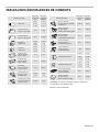
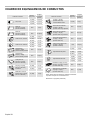
English 10
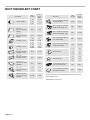
DUCT EQUIVALENT CHART
Size
(in./mm)
Eq u iva le n t
Length
(ft/m)
Size
(in./mm)
Eq u iva le n t
Length
(ft/m)
6 (152) 1.2 (0.37)
6 (152) 10 (3)
8 (203) 0.7 (0.21)
10 (254) 0.6 (0.18)
3¼" x 10"
(83 mm x 254 mm)
straight
N/A 1 (0.3)
3¼" x 10" (83 mm x 254 mm),
Center reverse elbow , right
N/A 25 (7.6)
3¼" x 14"
(83 mm x 356 mm)
straight
N/A 0.7 (0.21)
3¼" x 10" (83 mm x 254 mm),
Left reverse elbow
N/A 15 (4.6)
3¼" x 10" (83 mm x 254 mm),
Right reverse elbow
N/A 25 (7.6)
6 (152) 12 (3.7)
6 (152) 2 (0.6)
2 (0.6)
2 (0.6)
8 (203) 6 (1.8)
10 (254) 5 (1.5)
8 (203)
10 (254)
6 (152) 5 (1.5)
8 (203) 3 (0.9)
10 (254) 2 (0.6)
3¼" x 10"
(83 mm x 254 mm),
90° Elbow , round
N/A 5 (1.5)
2" (51 mm) long, 3¼" x 10"
(83 mm x 254 mm) flex
N/A 20 (6.1)
3¼" x 10"
(83 mm x 254 mm),
45° Elbow , round
N/A 15 (4.6)
3¼" x 10" (83 mm x 254 mm),
Roof jack and shutter
N/A 2 (0.6)
3¼" x 10"
(83 mm x 254 mm),
Flat elbow
N/A 20 (6.1)
6 (152) 5 (1.5)
8 (203) 2 (0.6)
6 (152) 10 (3)
NOTE: These commonly used installation parts can be purchased at
a local hardware store.
Measurements in inches (mm).
Round wall cap
Round roof cap
3¼" x 1
0" (83 mm x 254 mm)
to round 90° Elbow
Duct Pie ce
3¼" x 10" (83 mm x 254 mm)
Center reverse elbow , left
15 (4.6)N/A
3¼" x 10"
(83 mm x 254 mm)
to round
Round to 3¼" x 10"
(83 mm x 254 mm)
90° Elbow
Duct Pie ce
Smooth, straight
90° Elbow , round
45° Elbow , round
6 (152) 2 (0.6)
2 (0.6)
2 (0.6)
8 (203)
10 (254)

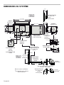
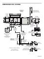
English 11
5.000”
(127)
7.976”
(203)
36.000” (914)
24.000”
(610)
5.272”
(134)
12.750”
(324)
15.952”
(405)
10.310”
(262)
33.152” (842)
14.048” (357)
17.478” (444)
6.478”
(165)
11.000”
(279)
12.750”
(324)
12.750” (324)
11.560” (294)
11.586”
(294)
4.240”
(108)
7.320”
(186)
11.586”
(294)
16.000” (406)
27.152” (690)
30.000” (762)
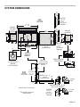
DHG602DUC
FLEX BLOWER
HDDREC5UC NON-DUCT
RECIRCULATION KIT
HDD2RECTD 1-7/8” X 19”
(48 x 483)
RECTANGULAR DUCT
HDD80051UC
HDD86051UC
DOWNDRAFT
HDDSTRAN8
1-7/8” X 19”
(48 x 483)
TO 8” (203) RD.
TRANSITION
HDDSTRAN8 1-7/8” X 19” (48 x 483)
TO 8” (203) RD. TRANSITION
8” (203) RD.
ELBOW
*
REAR
DUCTING
SIDE
DUCTING
FRONT
SIDE
DHG602DUC
FLEX BLOWER
HDD2RECTD 1-7/8” X 19”
(48 x 483)
RECTANGULAR DUCT
19.000”
(483)
FRONT
FRONT REAR
3.750”
(95)
INLET
OUTLET
OUTLET
FRONT
SIDE
HDDSTRAN2
1-7/8” X 19” (48 x 483)
RECTANGULAR DUCT
ADAPTER
HDDSTRAN6
1-7/8” X 19”
(48 x 483)
TO 6” (152) RD.
TRANSITION
HDDSTRAN6
1-7/8” X 19”
(48 x 483)
TO 6” (152) RD.
TRANSITION
HDDFTRAN6
6” (152) RD. DUCT PLATE
HDDFTRAN8
8” (203) RD. DUCT PLATE
C
L
C
L
OUTLET
29.750” (756)
(Chimney DOWN)
41.750” (1060)
(Chimney UP)
7.500”
(191)
6.000”
(152)
2.410”
(61)
24.000”
(610)
7.500”
(191)
6.000”
(152)
1.875”
(48)
7.500”
(191)
5.000”
(127)
7.500”
(191)
5.000”
(127)
6” (152) RD.
ELBOW
*
Measurements in inches (mm).
*
Not available from Bosch.
Purchase locally.
SYSTEM DIMENSIONS

English 12
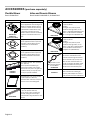
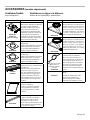
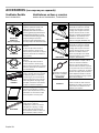
ACCESSORIES (purchase separately)
Flexible Blower
Bosch DHG602DUC
MODEL DESCRIPTION
HDDREC5UC
HDDFILTUC
(replacement fi lter)
Non-Duct Recirculating Kit
Used in applications where ducting is not
feasible or available. Mount to toe kick
or base of a cabinet and attach directly
to DHG602DUC Flexible Blower using
8” (203 mm) round duct. Kit can be
rotated so that the exhaust is not directly
at your feet. Includes decorative cover
plate.
HDDFTRAN6
Rough-in Plate - 6” (152 mm) Round
Use for applications where 6” (152 mm)
round duct or elbow attaches to front
of airbox (inline or remote blower
installation).
HDDFTRAN8
Rough-in Plate - 8” (203 mm) Round
Use for applications where 8” (203 mm)
round duct or elbow attaches to front
of airbox (DHG602DUC inline blower
installation).
HDD0RSP
HDD6RSP
Gas Cooktop Seal Kit - 30-in. (762 mm),
36-in. (914 mm)
Used to provide seal between gas
cooktop and downdraft. Also includes
cabinet hole cover plates. Two grilles are
provided in the kit, you may only need
one for your specifi c installation.
HDD2RECTD
Rectangular Duct - 2-ft. (0.6 m) sections
(1-7/8” x 19”/48 mm x 483 mm)
Galvanized steel construction 2-ft. (0.6 m)
sections can be connected together.
HDDSTRAN2
Rectangular Adapter for
1-7/8” x 19” (48 mm x 483 mm)
Use to connect 1-7/8” x 19” (48 mm x
483 mm) rectangular duct directly to
downdraft when using side, below or rear
exhaust.
MODEL DESCRIPTION
HDDSTRAN6
1-7/8” X 19” (48 mm x 483 mm) to
6” (152 mm) Round
Transition
Rectangular to 6” (152 mm) round
transition for left, right, below, or rear
exhaust - using Model DHG602DUC Flex
Blower. Can be attached to downdraft
unit or rectangular duct (HDD2RECTD).
HDDSTRAN8
1-7/8” X 19” (48 mm x 483 mm) to
8” (203 mm) Round
Transition
Rectangular to 8” (203 mm) round
transition for left, right, below, or rear
exhaust - using Inline or Remote Blower.
Can be attached to downdraft unit or
rectangular duct (HDD2RECTD).
B Connects to Hood
C Connects to Remote
or In-line Blower
EXTNCB25W
Extension Cable - 25-ft. (7.62 m)
The remote or inline blower harness
should be routed through the knockout
and secured with a 3/4” (19 mm) strain
relief. The 25-ft. Extension Cable can
then be connected to the Adapter Cable
included in EXTNSET4 Accessory Kit
and then to the hood electrical panel.
EXTNSET4
Extension Cable Connection Kit
Cable connection kit containing (4)
accessory cable adapters to connect a
variety of blower and hood combinations.
Inline and Remote Blowers
Bosch Models DHG6023RUC, DHG6015NUC
1
2
HA0146

English 13
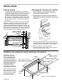
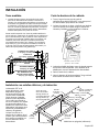
INSTALLATION
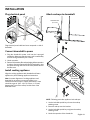
Cut countertop opening
1. Lay out and cut the cooktop cut-out far enough
FORWARD so downdraft will fi t behind it.
2. Set cooktop in place and slide it as far forward as
possible without exposing any gaps. Center and square
it with edges of countertop.
3. Place the plastic template against the back fl ange of the
cooktop. Center the template. Trace around template to
mark the downdraft opening.
4. Remove cooktop from countertop.
5. Cut downdraft opening. Be careful not to chip edges of
countertop.
Take measurements
1. Refer to the cooktop installation instructions for
dimensions of cooktop, countertop cut-out, and
cabinet requirements. However, it is recommended
that oversized cabinets be used for easier installation.
Custom island designs need to account for deeper
cabinets, especially when mounting the blower behind
the downdraft. You must also plan for an access door.
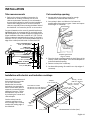
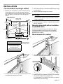
Pay special attention to the areas of potential interference
highlighted below. A countertop with (A) a raised lip and/or
(B) a backsplash may not allow enough fl at countertop for a
proper installation. Note that a minimum of 2-7/8” (73 mm)
of fl at countertop is required behind cooktop (C) and that a
minimum of 2-7/8” (73 mm) is necessary between the back
edge of the cooktop and the inside of cabinet back (D).
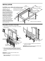
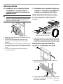
Installation with electric and induction cooktops
Dimension “BT” is thickness of
the backsplash that provides
1/2” (13 mm) clearance
between the vent and the
backsplash. Any backsplash
with a curved radius where it
meets the counter will require
additional clearance. Thicker
backsplashes may be used
by increasing the counter and
cabinet depths.
Set the cooktop into the
coutertop opening so that
the back edge of the cooktop
overlaps the leading edge of
the downdraft.
COUNTERTOP
COOKTOP
DOWNDRAFT
FRONT TO BACK
INSIDE CABINET DEPTH
FLAT COUNTERTOP (C)
2-7/8” (73 mm) MIN.
B
A
5/8” (16 mm) MIN.
2-7/8” (73 mm) MIN.
D
C
TEMPLATE
2-1/8” (54 mm) MIN.
Cooktop cutout width
2-1/4” (57 mm)
BT
MIN.
1/2”
(13 mm)
Downdraft cutout width:
30” (762 mm) is 27-1/16” (687 mm)
36” (914 mm) is 33-1/16” (840 mm)
Template
2-1/8” (54 mm)
19-7/8” - 20”
(505 mm - 508 mm)
22-11/16” - 22-13/16”
(576 mm - 579 mm)
25-7/16” - 25-9/16”
(646 mm - 649 mm)
11/16”
(17 mm)
Measurements in inches (mm).
Template against back
edge of cooktop.
COOKTOP

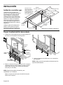
English 14
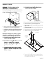
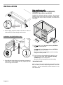
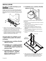
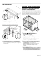
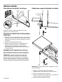
Prepare downdraft housing
1. Place the downdraft on its back on a table or fl at work
surface.
INSTALLATION
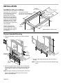
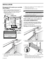
Installation with gas cooktops
Cooktop cutout width
1-7/8” (48 mm)
BT
MIN.
1/2”
(13 mm)
Downdraft cutout width:
30” (762 mm) is 27-1/16” (687 mm)
36” (914 mm) is 33-1/16” (840 mm)
Template
2-1/8” (54 mm)
19-1/8” (486 mm)
22-5/16” (567 mm)
24-11/16” (627 mm)
1-1/16”
(27 mm)
Dimension “BT” is thickness of
the backsplash that provides
1/2” (13 mm) clearance
between the vent and the
backsplash. Any backsplash
with a curved radius where it
meets the counter will require
additional clearance. Thicker
backsplashes may be used
by increasing the counter and
cabinet depths.
Set the cooktop into the
coutertop opening so that
the back edge of the cooktop
overlaps the leading edge of
the downdraft.
Measurements in inches (mm).
Screws
(discard)
Nut
(keep)
Support
Leg
Upper
Support
Brackets
Discharge
Covers
Nuts
(keep)
2. Detach the upper support brackets from the downdraft
by cutting off the tie wraps. Remove and set aside both
support legs from sides of the downdraft (one leg per
side).
NOTE: Discard the retaining screws, but KEEP THE NUTS.
Remove the bundle of 3 dischage covers from the
bottom of the downdraft.
3. Cover the discharge openings that won’t be used for
ducting.
NOTE: Use the nuts previously removed for side discharge
covers.

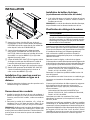
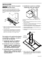
English 15
Optional: Electrical panel can be
mounted in a remote location.
Example: There is a drawer at the bottom of the cabinet, in
front of the downdraft. This may require the electrical panel
to be mounted in an adjacent cabinet. If blower discharge
is down, electrical panel must be relocated.
1. Remove (4) #8-32 hex nuts and electrical panel. Do not
mount with electrical panel slots facing downward.
2. Installation of a remotely located electrical panel may
be completed after connecting the ductwork and install
the blower. Install electrical panel according to local
codes.
INSTALLATION
Based on blower and ducting option
selected, go to the relevent section:
A - Installation using fl exible blower
attached to downdraft
B - Installation using fl exible or remote
blower - mounted in a remote
location - ducting through front
panel opening
C - Installation using inline or remote
blower - ducting through left, right,
below or rear
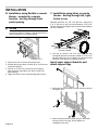
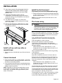
A - Installation using fl exible blower
attached to downdraft
(Purchase Model DHG602DUC Flexible Blower separately.)
1. Remove hex nuts to remove front panel cover.
2. Determine whether fl ex blower will discharge to the left,
right, or down.
3. If blower discharge is down, remove (4) #8-32 hex nuts
and electrical panel.
4. Place blower over studs around front panel opening.
5. Tighten hex nuts to secure blower in place.
BLOWER
SUPPORT
LEGS
(4) BOLTS
6. Remove bolts from fl ex blower housing. Attach blower
support legs to fl ex blower housing with these (4) bolts.
Do not tighten bolts at this time.

English 16
INSTALLATION
B - Installation using fl exible or remote
blower - mounted in a remote
location - ducting through front
panel opening
CAUTION
If fl exible blower is mounted as an inline blower: Do
not use legs alone for support. It may be necessary to
add extra support for the fl exible blower.
1. Remove hex nuts to remove front panel cover.
2. If blower discharge is down, remove (4) no. 8-32 hex nuts
and electrical panel.
3. Place 6” or 8” (152 mm or 203 mm) round rough-in
plate (purchase separately) over studs around front
panel opening.
4.
Tighten hex nuts to secure remote discharge plate in place.
C - Installation using inline or remote
blower - ducting through left, right,
below or rear
(Requires purchase of 1-7/8” x 19” (48 mm x 483 mm) to
6” or 8” (152 mm or 203 mm) round transition. 1-7/8” x 19”
(48 mm x 483 mm) rectangular duct and connection adapters
are also available.)
1. Use nuts to connect 1-7/8” x 19” (48 mm x 483 mm)
rectangular ductwork connection adapter or 1-7/8” x 19”
(48 mm x 483 mm) to 6” or 8” (152 mm or 203 mm) round
transition to housing when installing ductwork.
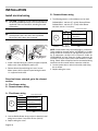
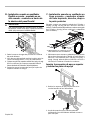
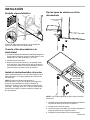
Insert upper support brackets and
attach support legs
1. Slide upper suport brackets into slide channel at top left
and right of unit.
2. Attach previously removed support legs to downdraft
using one nut for each leg. Do not tighten nut
completely at this time.
DUCTING OUT RIGHT SIDE OF
HOUSING SHOWN.

English 17
INSTALLATION
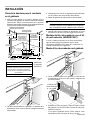
Cut out ductwork opening in cabinet
1. Measure and mark where to cut the ductwork opening
in the cabinet based on the ducting option selected.
Use the dimensions in the illustration below to help plan
how and where to provide duct access through your
cabinet.
Hole in Cabinet Floor
Dimension A
Using Flex Blower (Model DHG602DUC) &
8” (203 mm) round duct straight
down through cabinet fl oor.
(1½" /38 mm left of installation center line)
7¾ inches (197 mm)
2. Set downdraft into cabinet/countertop opening as far back
as possible and make sure it is level.
INSTALLATION
CENTER LINE
HOLE FOR
1
7
/
8
” x 19”
(48 mm x 483 mm)
DUCT &
TRANSITIONS
INSIDE
CABINET BACK
INSIDE
CABINET FLOOR
1½”
(38 mm)
21”
(533 mm)
centered
4” (102 mm)
21”
(533 mm)
A
REAR CORNER OF
COOKTOP CUT-OUT
24¾” (629 mm)
4 ”
(105 mm)
/
8
1
5 ”
(149 mm)
/
8
7
4”
(102 mm)
Measurements
in inches (mm).
3. Check that markings in cabinet line up with ducting coming
from downdraft.
4. Remove downdraft housing from cabinet.
CAUTION
Before cutting hole in cabinet for ductwork, check
for interference with fl oor joists, wall studs, electrical
wiring or plumbing.
5. Cut ductwork hole in cabinet - as well as holes in wall or
fl oor as necessary.
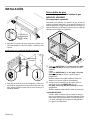
Mounting downdraft with recirculation
kit (HDDREC5UC)
If unit is to be installed using a recirculation kit, please
follow the installation instructions for the recirculation
kit (HDDREC5UC) prior to installing and mounting the
downdraft in the cabinet.
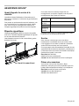
Mount downdraft in cabinet
1. Set downdraft into cabinet/countertop opening as far back
as possible and make sure it is level.
2. Extend support legs and attach to bottom of cabinet with
(2) screws through each leg. Tighten nuts.
If cabinet bottom is removed: Use blocks as spacers
between fl oor and support legs.
1
1
2 No. 10 x 0.500
WOOD SCREW

English 18
INSTALLATION
3. Extend upper support brackets and attach to sides of
cabinet with (2) screws through each bracket.
Installations using fl exible blower only:
4. Extend blower support legs and secure them to bottom of
cabinet with a screw through each leg. Tighten (4) bolts
to secure legs to fl ex blower.
2 No. 10 x 0.500
WOOD SCREW
1
FLEXIBLE
BLOWER
(4)
BOLTS
Gas cooktops only:
Install gas cooktop seal kit (HDD0RSP,
HDD6RSP) (purchase separately)
Available for application with gas cooktops - where proper
sealing is required and holes are required in cabinet base.
Kit includes trim seal, toe-kick cover plate, and cabinet hole
cover plate.
B Cut one 18¼” x 2½” (464 mm x 64 mm) OPENING
(A)* in the cabinet toe kick.
-- or --
Cut one 18¼” x 2½” (464 mm x 64 mm) OPENING
(B) in the cabinet side or back.
Mount one of the two metal grilles over this opening,
using two screws provided.
C
If you chose to cut an opening in the toe kick - you
must cut another 18¼” x 2½” (464 mm x 64 mm)
OPENING (C)* in the cabinet fl oor.
Mount the second metal grille over this opening.
* IMPORTANT NOTE:
When using toe kick opening (A) with opening (C) in cabinet
fl oor: Air must be able to fl ow freely between these two
openings - and not restricted by cabinet structure or any
other obstruction.
A
B
A
B
B
C
B
B
C

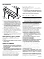
English 19
Install the electrical panel
(if previously removed from downdraft housing)
1. If electrical panel was removed from the downdraft housing
in order to mount it in a remote location: Mount electrical
panel in chosen location.
NOTE: Do not mount electrical panel with slots in cover
facing downward.
D
Clean housing surface (B) with Isopropyl Alcohol or
Rubbing Alcohol. Remove TAPE STRIPS to reveal
adhesive side of tape from the back side of TRIM
BRACKET (A).
ECenter trim bracket left-to-right at TOP OF
DOWNDRAFT HOUSING (B). Stick trim bracket to
downdraft housing so that FLANGES (C) and (D) are
fl ush with each other.
FCut TRIM SEAL (E) to length: No shorter than
downdraft countertop cutout opening and no longer
than cooktop width.
G Remove tape backing from TRIM SEAL (E). Center
trim seal left-to-right and stick trim seal across both
FLANGES (C) and (D).
F
G
D
E
C
A
B
D
E
INSTALLATION
Install roof cap, wall cap, inline or
remote blower
1. Follow instructions included with caps, inline and remote
blower.
Connect ductwork
1. From roof cap, wall cap, or remote blower - work back
towards the cabinet, attaching all ductwork, elbows and
transitions as previously planned.
2. Connect ductwork (and transition, if required) to fl ex blower
or downdraft. If necessary, use (2) no. 8-18 x .375 (9.5 mm)
Phillips screws for transition.
NOTE: Regardless of blower placement/exhaust, ensure
that all seams are properly taped - to make them secure
and air-tight. This includes seams/gaps between panels
and/or on the blower.
Plan house wiring
WARNING
RISK OF ELECTRIC SHOCK
Parts inside the appliance can have sharp edges. The
connection cable can be damaged. Do not bend or
pinch connection cables during installation.
Before connecting the appliance, check the house wiring
to make sure it has suffi cient circuit protection. The voltage
and frequency of the appliance must match the electrical
installation (see rating plate).
Only a qualifi ed electrician following all appropriate
regulations may lay or replace the connecting cable.
Follow all regulations, codes, and laws.
Ensure that the electrical connection meets the
requirements of the latest version of all regulations,
codes, and laws in the appropriate country, especially the
following standards:
National Electrical Code, ANSI/ NFPA 70, or CSA
Standards C22.1-94, Canadian Electrical Code, Part 1
and C22.2 No.0-M91, UL 507.
Have a qualifi ed electrical technician check the grounding
of the appliance.
Do not ground to a gas line.
Keep these installation instructions for future reference.
Ensure that the wire diameter meets the requirements of
the latest version of all applicable regulations, codes, and
laws in the appropriate country, especially the following
standards:
National Electrical Code, ANSI/NFPA 70, or CSA
Standards C22.1-94, Canadian Electrical Code, Part 1
and C22.2 No.0-M91.
The downdraft with the Flex Blower (purchase separately)
draws 3.0 Amps and requires a 120 VAC, 60 Hz circuit.
The downdraft with Remote Blower Models DHG6015NUC
and DHG6023RUC (purchase separately) draws 5.0 Amps
(max.) and requires a 120 VAC, 60 Hz circuit.
The downdraft has a 30-in. (762 mm) long power cord with
a 3-pronged plug. Plan to provide a grounded outlet in a
location which will allow the power cord to reach.

English 20
INSTALLATION
Install electrical wiring
CAUTION: Installation work and electrical wiring must
be done by qualifi ed person(s) in accordance with all
applicable codes and standards, including fi re-rated
construction.
CAUTION: Do not use an extension cord. If the
product power cord is too short, have a qualifi ed
electrician install a three slot receptacle.
1. Install a standard wiring box, with 3-pronged receptacle,
within reach of the downdraft’s power cord.
2. Remove electrical panel wiring box cover. Secure
blower power cable to electrical panel wiring box with
U.L. approved strain relief.
Based on blower selected, go to the relevent
section:
A - Flex blower wiring
B - Remote blower wiring
A - Flex blower wiring
3. Connect fl exible blower wires to wires in electrical panel
wiring box as shown. Cap off BLUE wire (LOW 1).
4. Replace wiring box cover.
From exterior or
in-line blower
FLEXIBLE
BLOWER
M
ELECTRICAL PANEL
WIRING
BOX
BROWN (HIGH 4)
WHITE (NEUTRAL)
RED (MED 2)
GROUND SCREW
ORANGE (MED-HIGH 3)
BLACK
WHITE
BLUE (cap off)
RED
ORANGE
GREEN
B - Remote blower wiring
3. The following exterior or inline blowers can be used:
DHG6023RUC - 600 cfm (17 m
3
/min) Remote Blower
DHG6015NUC - 600 cfm (17 m
3
/min) Inline Blower
120 VAC 60 Hz 5.0 A (max.)
NOTE: Some blowers may come with plugs or connectors.
These should be removed and the 14/4 ROMEX or Conduit
wiring should be connected in and approved junction box.
As an alternative, the BSH 25-ft. Extension Cable Kit
(EXTNCB25W) and the Extension Cable Connection Kit
(EXTNSET4) can be used in place of the ROMEX or conduit
wiring. Please follow all required and recommended wiring
instructions in this manual and the extension cable kits.
4. Connect power wires to wires in electrical panel wiring
box as shown.
5. Replace wiring box cover.
REMOTE
BLOWER
M
ELECTRICAL PANEL
WIRING
BOX
BROWN (HIGH 4)
WHITE (NEUTRAL)
RED (MED 2)
GROUND SCREW
ORANGE (MED-HIGH 3)
14/4 ROMEX
OR CONDUIT
La page est en cours de chargement...
La page est en cours de chargement...
La page est en cours de chargement...
La page est en cours de chargement...
La page est en cours de chargement...
La page est en cours de chargement...
La page est en cours de chargement...
La page est en cours de chargement...
La page est en cours de chargement...
La page est en cours de chargement...
La page est en cours de chargement...
La page est en cours de chargement...
La page est en cours de chargement...
La page est en cours de chargement...
La page est en cours de chargement...
La page est en cours de chargement...
La page est en cours de chargement...
La page est en cours de chargement...
La page est en cours de chargement...
La page est en cours de chargement...
La page est en cours de chargement...
La page est en cours de chargement...
La page est en cours de chargement...
La page est en cours de chargement...
La page est en cours de chargement...
La page est en cours de chargement...
La page est en cours de chargement...
La page est en cours de chargement...
La page est en cours de chargement...
La page est en cours de chargement...
La page est en cours de chargement...
La page est en cours de chargement...
La page est en cours de chargement...
La page est en cours de chargement...
La page est en cours de chargement...
La page est en cours de chargement...
La page est en cours de chargement...
La page est en cours de chargement...
La page est en cours de chargement...
La page est en cours de chargement...
La page est en cours de chargement...
La page est en cours de chargement...
La page est en cours de chargement...
La page est en cours de chargement...
-
 1
1
-
 2
2
-
 3
3
-
 4
4
-
 5
5
-
 6
6
-
 7
7
-
 8
8
-
 9
9
-
 10
10
-
 11
11
-
 12
12
-
 13
13
-
 14
14
-
 15
15
-
 16
16
-
 17
17
-
 18
18
-
 19
19
-
 20
20
-
 21
21
-
 22
22
-
 23
23
-
 24
24
-
 25
25
-
 26
26
-
 27
27
-
 28
28
-
 29
29
-
 30
30
-
 31
31
-
 32
32
-
 33
33
-
 34
34
-
 35
35
-
 36
36
-
 37
37
-
 38
38
-
 39
39
-
 40
40
-
 41
41
-
 42
42
-
 43
43
-
 44
44
-
 45
45
-
 46
46
-
 47
47
-
 48
48
-
 49
49
-
 50
50
-
 51
51
-
 52
52
-
 53
53
-
 54
54
-
 55
55
-
 56
56
-
 57
57
-
 58
58
-
 59
59
-
 60
60
-
 61
61
-
 62
62
-
 63
63
-
 64
64


Bosch HDD80051UC Guide d'installation
- Taper
- Guide d'installation
- Ce manuel convient également à
dans d''autres langues
- español: Bosch HDD80051UC Guía de instalación
Documents connexes
-
Bosch HDD6RSP(00) Guide d'installation
-
Bosch HDD86051UC Guide d'installation
-
Bosch HDD86051UC Le manuel du propriétaire
-
-
-
Bosch HDD80050UC Guide d'installation
-
-
Bosch DHG602DUC/01 Guide d'installation
-
Thermador DHD3014UC Guide d'installation
-
Autres documents
-
Thermador UCVM30XS Mode d'emploi
-
Thermador 1071394 Guide d'installation
-
Best ATSKD48 Guide d'installation
-
Viking ARKD Guide d'installation
-
Viking Range ARKD Guide d'installation
-
Viking VDD5450SS Guide d'installation
-
Viking Range 36" Range/Rangetop downdraft trim Guide d'installation
-
-
Best D49M36SB Guide d'installation
-
Thermador UCV36ST Guide d'installation