Epson EB-1420Wi Manuel utilisateur
- Catégorie
- Projecteurs
- Taper
- Manuel utilisateur

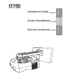
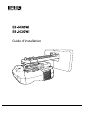
Installation Guide
Guide d’installation
Guía de instalación
EnglishFrançaisEspañol


Using the Product Safely
1
Safety Instructions
For your safety, read all the instructions in this guide before using this product. Incorrect handling that ignores
instructions in this guide could damage this product or could result in personal injury or property damage.
Keep this installation guide at hand for future reference.
Read the User's Guide and Safety Instructions for your projector and follow the instructions in these documents.
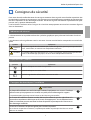
Safety indications
The documentation and this product use graphical symbols to show how to use this product safely.
The indications and their meaning are as follows. Make sure you understand them properly before reading
the guide.
Symbol Explanation
Warning
This symbol indicates information that, if ignored, could possibly result in personal injury or
even death due to incorrect handling.
Caution
This symbol indicates information that, if ignored, could possibly result in personal injury or
physical damage due to incorrect handling.
Explanation of Symbols
Symbols Explanation
Symbol indicating an action that must not be done
Symbol indicating an action that should be done
c
Symbol indicating related or useful information
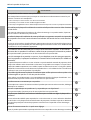
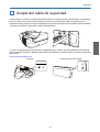
Safety Precautions for Installation
Warning
The setting plate is exclusively for mounting the projector on a wall. If anything other than
a projector is mounted, the weight may result in damage.
If this product falls, it could cause death or personal injury.
The installation work (wall mounting) should be performed by specialists who have tech‐
nical knowledge and ability. Incomplete or incorrect installation could cause the product
to fall and cause personal injury or property damage.
Follow the instructions in this guide when installing this product.
If the instructions are not followed, this product may fall, resulting in personal injury or an accident.

Using the Product Safely
2
Warning
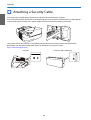
Handle the power cord carefully.
Incorrect handling may cause fire or electric shock. Observe the following precautions when han‐
dling:
•
Do not handle the power plug with wet hands.
•
Do not use a power cord that is damaged or modified.
•
Do not pull the power cord with too much force when routing the cable through the setting plate.
Do not install the setting plate in a place where it might be subjected to vibration or shock.
This could cause damage to the product or mounting surface. If this product falls, it could cause
death or personal injury.
Install the setting plate so that it can sufficiently support the mass of the projector and
setting plate, and resist any horizontal vibration. Use M10 nuts and bolts.
Nuts and bolts smaller than M10 could cause the setting plate to fall. Epson accepts no responsibility
for any damage or injury caused by lack of wall strength or inadequate installation.
The installation work should be performed by at least two qualified service personnel. If
you need to loosen any screws during installation, be careful not to drop this product.
If this product falls, it could cause death or personal injury.
When mounting this product on a wall, the wall requires enough strength to hold the
projector, the setting plate, the Control Pad, and the Touch Unit (EB-1430Wi only).
This product should be installed on a concrete wall. The maximum combined weight of the pro‐
jector, the setting plate, and the Control Pad is approximately 14 kg (not including cables). When
the Touch Unit (EB-1430Wi only) is installed, the maximum weight is approximately 14.5 kg (not
including cables). Ensure the strength of the wall before mounting this product on the wall. If the
wall is not strong enough, reinforce the wall before installation.
Inspect the setting plate on a regular basis to ensure there are no broken parts or loose
screws.
If any parts are damaged, stop using the setting plate immediately. If this product falls, it could
cause death or personal injury.
Do not disassemble or remodel this product.
There are numerous high-voltage sections inside the product that could cause a fire, electric shock,
or an accident.
Do not hang on this product or hang a heavy object on this product.
If this product falls, it could cause death or personal injury.
Do not use adhesives, lubricants, or oils to install or adjust the setting plate.
If you use adhesives to prevent the screws from loosening or things such as lubricants or oils on
the slide plate fixing part of the projector, the case may crack and cause the projector to fall,
resulting in personal injury or property damage.
Tighten all screws firmly after adjustment.
Otherwise, the product may fall and cause personal injury or property damage.
Never loosen the bolts and nuts after installation.
Confirm that the screws have not become loose on a regular basis. If you find any loose screws,
tighten them firmly. Otherwise, the product may fall and cause personal injury or property damage.
Route the cables so that they do not interfere with the nuts and bolts.
Incorrect handling of the cables may cause fire or electric shock.

Using the Product Safely
3
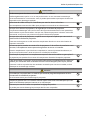
Warning
When turning on the projector, do not look into the projection window.
This could cause damage to eyesight due to the powerful light emitted. Take particular care when
there are children present. When turning on the projector at a distance using the remote control,
make sure there is no one looking into the projection window.
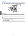
When using the projector, do not place any objects or put your hand near the projection
window.
This area is dangerous as it reaches a high temperature due to the concentrated projection light.
Do not cover the projector's air intake vent or air exhaust vent. If either of the vents are
covered, the internal temperature could rise and cause a fire.
Avoid locations subject to high temperatures, such as close to heaters, and leave a gap of at least
20 cm between the wall and the air exhaust vent.
Do not use the projector in a location subject to combustible or explosive gas.
The projector may catch fire because of the high temperature of the lamp inside the projector.
If any abnormalities occur with this product, immediately disconnect the cables from the
product, and then contact your local dealer or the nearest Epson service call center.
Continuing to use the product in an abnormal condition could cause a fire, electric shock, or visual
impairment.
Caution
Do not install this product in a location where the operating temperature for your projector
model may be exceeded.
Such an environment may damage the projector.
Install this product in a place free from excessive dust and humidity to prevent the lens or
optical components from becoming dirty.
Do not use excessive force when adjusting this product.
This product may break, resulting in personal injury.
Notes on handling the Touch Unit (EB-1430Wi only)
Warning
Do not disassemble or remodel the Touch Unit.
The Touch Unit contains a high power laser product that could cause a fire, electric shock, or an
accident.
Follow the instructions in this guide to setup and operate the Touch Unit.
If the Touch Unit is not setup and operated correctly, it could cause damage to eyesight due to
light from the laser.
Do not apply optical devices such as a magnifying glass or telescope to the laser light
diffused from the Touch Unit.
Using it in this condition could have a negative influence on the human body. It could also cause
a fire or accident.

Using the Product Safely
4
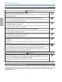
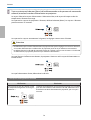
Warning
Do not look into the Touch Unit's laser diffusion ports.
This could cause damage to eyesight due to the powerful laser light emitted. Take particular care
when there are children present.
Do not view the laser light using optical devices such as a magnifying glass within a range
of 70 mm from the Touch Unit's laser diffusion ports.
This could cause visual impairment.
Only connect the Touch Unit to the EB-1430Wi. Do not connect it to any other projectors
or devices.
The device could malfunction, or laser light could leak beyond its restricted area.
Do not go near the Touch Unit if you are using medical equipment such as a pace maker.
Furthermore, when using the Touch Unit, make sure there is no one using medical equip‐
ment such as a pace maker, in the surrounding area.
A powerful magnet within the unit generates electromagnetic interference which may cause med‐
ical equipment to malfunction.
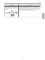
Caution
Do not go near the Touch Unit with magnetic storage media such as magnetic cards, or
precision electronic devices such as computers, digital watches, or mobile phones.
A powerful magnet within the unit could corrupt data or cause a malfunction.
About This Installation Guide
This guide describes how to mount the short-throw projector EB-1430Wi/EB-1420Wi on a wall. It also explains
how to install the Control Pad and the Touch Unit (EB-1430Wi only) after mounting on a wall.

Using the Product Safely
5
Choosing an Installation Location
Projector installation location
•
Carry out power supply wiring work for the installation location of the setting plate in advance.
•
Install the projector away from other electric devices such as fluorescent lights or air conditioners. Some kinds of
fluorescent lights could interfere with the remote control of the projector.
•
It is recommended to keep connection cable length less than 20 meters to reduce external noise.
•
We recommend using stick-on screens or board screens.
•
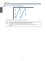
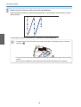
Make sure the projector is installed under the following conditions.
•
The projected image is a rectangular shape without any distortion.
•
The projector is tilted at an angle of no more than ±3° vertically and horizontally in relation to the screen.
•
When using the interactive function (Easy Interactive Function), install so that the projected image is within reach.
•
Do not install the projector or the screen in a location subject to direct sunlight. If the projector or the screen are
subject to direct sunlight, the interactive function may not operate correctly.
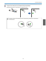
Control Pad installation location
When powering the Control Pad using batteries, make sure the installation location meets the following
requirements.
•
Install the Control Pad on the same surface as the projection screen.
If the projection screen and the Control Pad installation point are uneven, install the Control Pad approximately 20
cm from the edge of the screen.
•
Make sure there are no obstacles between the Control Pad and the projector (not including the Touch Unit).
In the following situations, use the optional Remote control cable set (ELPKC28) to supply power to the
Control Pad from the projector.
•
When the requirements mentioned above are not met.
•
When the projection screen and the Control Pad installation point are uneven and the difference in height is more
than 5 cm
•
When the projector is placed on a table and projecting to the screen.
•
When multiple projectors are being used.
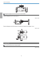
Touch Unit installation location (EB-1430Wi only)
•
When using the Touch Unit, install the projector using one of the following methods. The Touch Unit cannot be used
if another installation method is used.
•
Mount the projector on a wall or suspend it from a ceiling and project images from in front of the screen.
•
Install vertically on a table and project from the front of the table. (When installing vertically on a table, you need
the optional Interactive Table Mount (ELPMB29).)
•
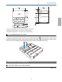
Before installing the Touch Unit, make sure that the installation location meets the following conditions.
•
The Touch Unit can be secured with magnets or with screws.
•
A flat, smooth, unwarped surface with no unevenness on the screen surface of more than 5 mm.

Using the Product Safely
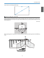
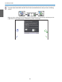
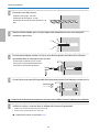
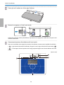
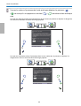
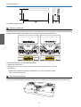
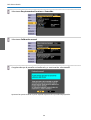
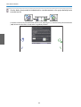
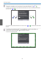
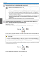
6
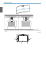
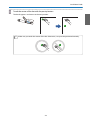
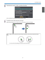
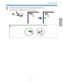
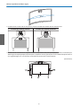
•
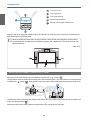
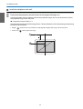
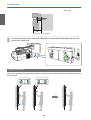
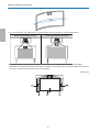
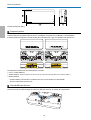
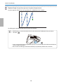
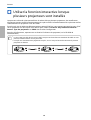
When installing on a whiteboard, install the Touch Unit within the frame of the whiteboard.
Correct installation position Incorrect installation position
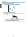
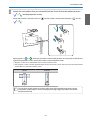
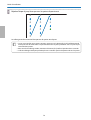
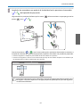
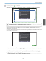
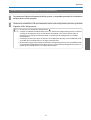
•
When installing the Touch Unit, make sure there are no obstacles, such as cables, or protruding items such as
whiteboard trays, holders, or thick frames in the shaded areas in the following figure. The Touch Unit will not operate
correctly.
[Unit: mm]

Contents
7
Using the Product Safely
Safety Instructions .................... 1
Safety indications.......................1
Explanation of Symbols...................1
Safety Precautions for Installation............1
Notes on handling the Touch Unit (EB-1430Wi
only) ................................. 3
About This Installation Guide...............4
Choosing an Installation Location ...... 5
Projector installation location...............5
Control Pad installation location.............5
Touch Unit installation location (EB-1430Wi only)
.....................................5
Installation Guide
Installation Work Flow ................ 9
Package Contents .................... 10
Setting plate ..........................10
Control Pad ...........................11
Touch Unit (EB-1430Wi only) ............... 11
Specifications ....................... 12
Setting plate ..........................12
Wall plate .......................... 12
Vertical slide adjustment range ........... 13
Horizontal slide adjustment range ......... 13
Forward/backward slide adjustment range
.................................. 13
Control Pad ...........................14
Control Pad (external dimensions/weight)
.................................. 14
Cable routing holes ...................14
Touch Unit (EB-1430Wi only) ............... 15
Touch Unit (external dimensions/weight)
.................................. 15
Attached labels ...................... 15
Laser diffusion port...................16
Projection Distance Table ............ 17
Figures of Installation Dimensions ........... 17
When installing the Touch Unit (EB-1430Wi
only) .............................. 17
When installing the Control Pad..........19
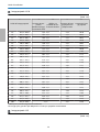
When Projected Image is Smaller than 75 Inches
....................................20
16:10 projected image .................21
16:9 projected image .................. 21
4:3 projected image ...................22
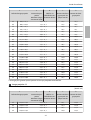
When Projected Image is Larger than 75 Inches
....................................23
16:10 projected image .................24
16:9 projected image .................. 25
4:3 projected image ...................25
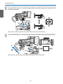
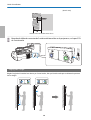
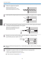
Installing the Setting Plate ........... 27
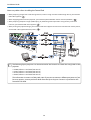
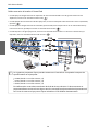
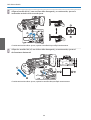
Connecting Devices ..................... 27
Necessary cables.....................27
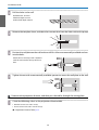
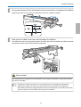
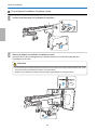
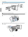
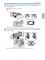
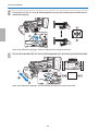
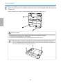
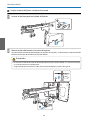
Installation Procedure...................30
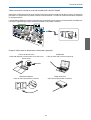
Disassemble the parts.................30
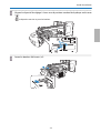
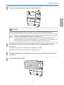
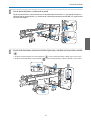
Assemble the parts...................30
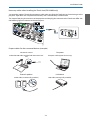
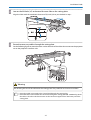
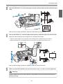
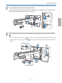
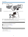
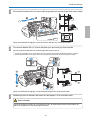
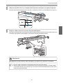
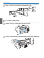
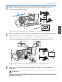
Install the wall plate on the wall..........32
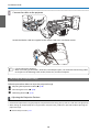
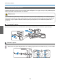
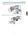
Determine the projection distance, and then
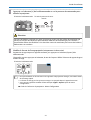
pass the cables through the setting plate . . . . 34
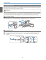
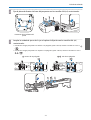
Attaching the setting plate to the wall plate
.................................. 36
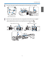
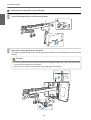
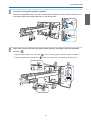
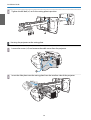
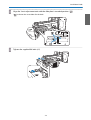
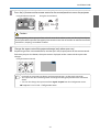
Securing the projector to the setting plate
.................................. 38
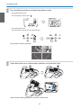
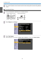
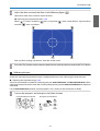
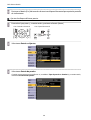
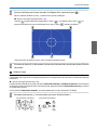
Adjusting the Projected Image.............40
Adjusting the Projection Position.........40
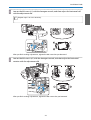
Fine-tuning the Focus.................46
Calibrating the pen ...................47
Attaching the Covers .................... 51
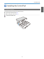
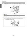
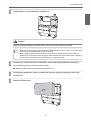
Installing the Control Pad ............ 53
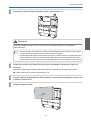
Installation Procedure...................53
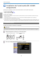
Installing the Touch Unit (EB-1430Wi
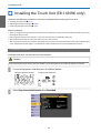
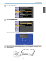
only) ................................ 56
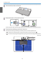
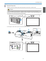
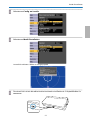
Installation Procedure...................56
Angle Adjustment ...................... 60
Touch Calibration......................71
Appendix
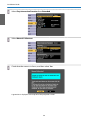
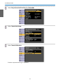
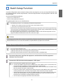
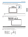
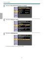
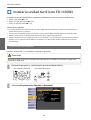
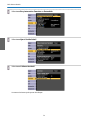
Batch Setup Function ................ 75
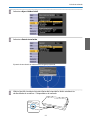
Saving settings to the USB flash drive........75
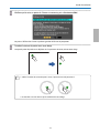
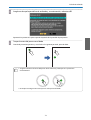
Reflecting saved settings to other projectors
....................................76
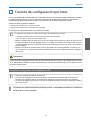
When Setup Fails ....................... 77


Installation Guide
9
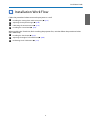
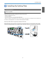
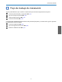
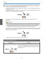
Installation Work Flow
Follow the procedures below to mount the projector on a wall.
a
Installing the Setting Plate and the Projector (s p.27)
b
Adjusting the Projected Image (s p.40)
c
Calibrating the Interactive Pen (s p.47)
d
Installing the Control Pad (s p.53)
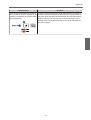
When installing the Touch Unit, finish installing the projector first, and then follow the procedures below
(EB-1430Wi only).
a
Installing the Touch Unit (s p.56)
b
Adjusting the Angle of Laser Diffusion (s p.60)
c
Performing Touch Calibration (s p.71)

Installation Guide
10
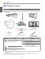
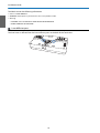
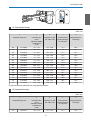
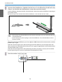
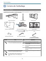
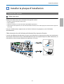
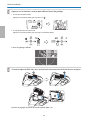
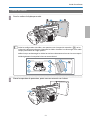
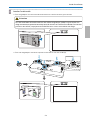
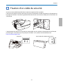
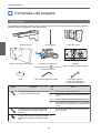
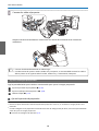
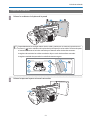
Package Contents
Setting plate
The following supplied items are necessary to mount the projector on a wall. Confirm that you have all items
before beginning.
Setting plate Hexagonal axis Wall plate
Wall plate cover 3-axis adjustment unit
*The slide plate (
) is secured dur‐
ing shipping.
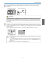
Template sheet
(for installing the wall plate)
End cap Hexagon wrench (for M4) Open-ended spanner
13 mm (for M8 and M6),
6 mm (for hexagonal axis)
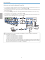
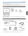
Shape Name
Quan‐
tity
Application
M4 x 12 mm hexagon socket head cap bolt
with washer/spring washer
6For wall plate assembly
4 For 3-axis adjustment unit/arm installation
4 For slide plate/projector installation
2 For slide plate/3-axis adjustment unit installa‐
tion (attached during shipping)
M6 x 20 mm hexagon shoulder head bolt
with washer/spring washer
1 For setting plate/wall plate installation
M6 x 20 mm cross recessed head shoulder
screws with plastic washers
3
•
Use the bolts or screws supplied with this product to install it as directed in this guide. Do not substitute these bolts
with any other types.
•
You need to use commercially available M10 x 60 mm anchors (at least 3) to attach the wall plate to the wall.
•
Gather the tools and parts you need before you begin installation.

Installation Guide
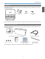
11
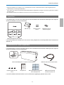
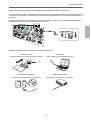
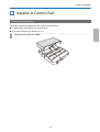
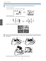
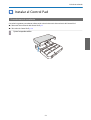
Control Pad
The following supplied products are necessary when attaching the Control Pad. Confirm that you have all
items before beginning.
AA size batteries
(x2)
Rubber feet Port protection
stickers
Control Pad main unit
When installing the Control Pad on a wall and so on, prepare commercially available M4 screws (20 mm x4).
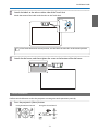
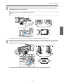
Touch Unit (EB-1430Wi only)
The following supplied products are necessary when attaching the Touch Unit. Confirm that you have all
items before beginning.
Touch Unit/Markers x2 (attached to Touch Unit) Touch Unit connection cable
Spacer for screw hole x3 Label x4 Tape (approx. 6 cm) for secur‐
ing the marker x12
Infrared deflector
(approx. 28.5 cm) x8
When installing the Touch Unit on a non-magnetic surface, prepare three M4 screws.

Installation Guide
12
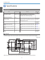
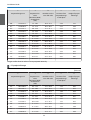
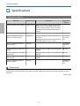
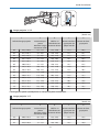
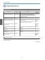
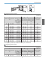
Specifications
Setting plate
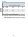
Item Specification Remark Reference
Page
Setting plate weight Approx. 8.1 kg Setting plate (3.0 kg), 3-axis adjustment unit
(1.2 kg), slide plate (0.8 kg), wall plate (2.7 kg),
wall plate cover and end cap (0.4 kg)
Maximum load capacity 7 kg
Forward/backward slide ad‐
justment range
0 to 360 mm Arm slide adjustment range: 0 to 273 mm
Adjustment for 3-axis adjustment unit instal‐
lation position: 87 mm
See the fig‐
ure below
Vertical slide adjustment range ±38 mm See the fig‐
ure below
Horizontal roll adjustment
range
±3° Fine adjustments possible with adjustment
dial
s p.40
Horizontal rotation adjustment
range
±8° Fine adjustments possible with adjustment
dial
s p.40
Vertical tilt adjustment range ±3° Fine adjustments possible with adjustment
dial
s p.40
Horizontal slide adjustment
range
±45 mm See the fig‐
ure below
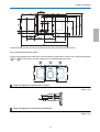
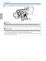
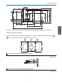
Wall plate
The following figure shows three wall plates connected to form one plate (separate when shipped).
[Unit: mm]
*
Offset value for the position of the center of the projected image and the center of the wall plate

Installation Guide
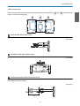
13
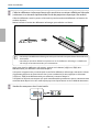
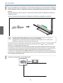
Cable routing holes
When routing cables to connect to the projector through a wall, use positions ( ) and ( ) in the following
figure as the cable routing holes.
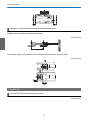
Vertical slide adjustment range
[Unit: mm]
Horizontal slide adjustment range
[Unit: mm]
Forward/backward slide adjustment range
Arm slide adjustment range
[Unit: mm]

Installation Guide
14
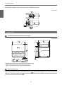
Adjustment range for 3-axis adjustment unit installation position
[Unit: mm]
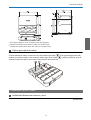
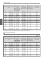
Control Pad
Control Pad (external dimensions/weight)
[Unit: mm]
•
Weight: approx. 240 g (not including batteries and rubber feet)
•
Operating temperature: 0 to +50°C (no condensation)
•
Operating temperature: -20 to +60°C (no condensation)
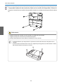
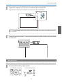
Cable routing holes
When routing cables through a wall, use the position ( ) in the following figure as the cable routing hole.
Otherwise, remove the cable cover (
) and route the cables from there. Route the printer cable along the
groove at the back of the Control Pad.

Installation Guide
15
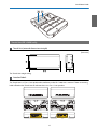
Touch Unit (EB-1430Wi only)
Touch Unit (external dimensions/weight)
[Unit: mm]
The Touch Unit weighs 450 g.
Attached labels
The Touch Unit is a Class 1 laser product that conforms to the JIS C 6802:2011 standard. There are warning
labels affixed to the Touch Unit to indicate that it is a Class 1 laser product.

Installation Guide
16
The labels contain the following information.
•
CLASS 1 LASER PRODUCT
•
WARNING: Never open any covers on this unit. Laser product inside.
•
Warning:
•
CAUTION: CLASS 3B INVISIBLE LASER RADIATION WHEN OPEN.
•
AVOID EXPOSURE TO THE BEAM
Laser diffusion port
The laser beam is diffused from the laser diffusion ports at the back of the Touch Unit.

Installation Guide
17
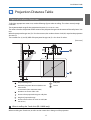
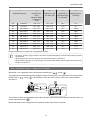
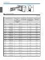
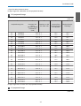
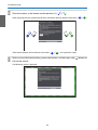
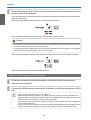
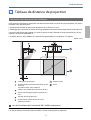
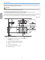
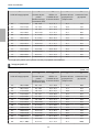
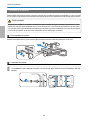
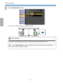
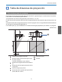
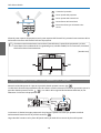
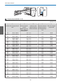
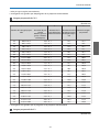
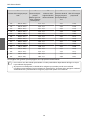
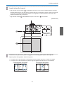
Projection Distance Table
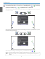
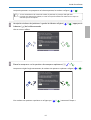
Figures of Installation Dimensions
To find the appropriate screen size, see the following figures when installing. The values are only rough
estimates.
The recommended range for the projection distance (a) is 62 to 311 mm.
The offset value for the position of the center of the projected image and the center of the wall plate is 70.5
mm.
When the projected image size (S) is 75 inches or more, the scale on the arm slide (b) is equal to the projection
distance (a).
The numbers for (a) and (b) differ if the projected image size (S) is less than 75 inches.
[Unit: mm]
:
Projected image size
:
Wall plate
:
Minimum projection distance (Wide: maxi‐
mum zoom)
to maximum (Tele: minimum zoom)
:
Screen
:
Numbers on the arm slide scale
:
Distance from projected image to wall plate
:
Height of projected image
:
Distance from surface of screen to wall (100
mm or less)
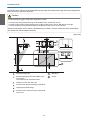
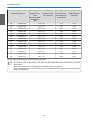
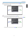
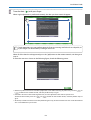
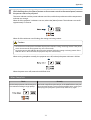
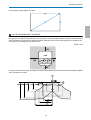
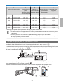
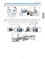
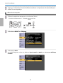
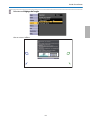
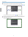
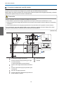
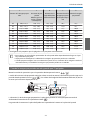
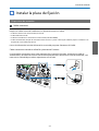
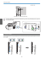
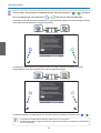
When installing the Touch Unit (EB-1430Wi only)
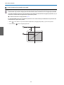
When installing the Touch Unit, install it on the screen that is being used for projection.

Installation Guide
18
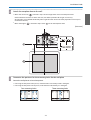
You need at least 120 mm distance between the top edge of the projected image and the top edge of the
actual screen to install the Touch Unit.
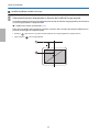
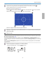
Caution
Leave the following gaps around the edge of the screen.
•
From the top of the projected image to the bottom of the Touch Unit: 25 mm
•
From the edges of the projected image to the edges of the screen: At least 100 mm left and right
•
From the bottom of the projected image to the bottom of the screen: At least 20 mm
If there are obstacles such as cables, whiteboard trays, holders, or frames within the areas noted above,
the Touch Unit will not operate correctly.
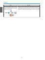
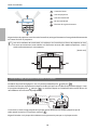
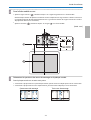
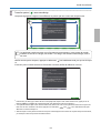
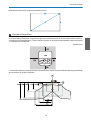
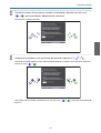
[Unit: mm]
:
Projected image size
:
Wall plate
:
Minimum projection distance (Wide: maxi‐
mum zoom)
to maximum (Tele: minimum zoom)
:
Screen
:
Numbers on the arm slide scale
:
Distance from projected image to wall plate
:
Height of projected image
:
Distance from surface of screen to wall (100
mm or less)
La page est en cours de chargement...
La page est en cours de chargement...
La page est en cours de chargement...
La page est en cours de chargement...
La page est en cours de chargement...
La page est en cours de chargement...
La page est en cours de chargement...
La page est en cours de chargement...
La page est en cours de chargement...
La page est en cours de chargement...
La page est en cours de chargement...
La page est en cours de chargement...
La page est en cours de chargement...
La page est en cours de chargement...
La page est en cours de chargement...
La page est en cours de chargement...
La page est en cours de chargement...
La page est en cours de chargement...
La page est en cours de chargement...
La page est en cours de chargement...
La page est en cours de chargement...
La page est en cours de chargement...
La page est en cours de chargement...
La page est en cours de chargement...
La page est en cours de chargement...
La page est en cours de chargement...
La page est en cours de chargement...
La page est en cours de chargement...
La page est en cours de chargement...
La page est en cours de chargement...
La page est en cours de chargement...
La page est en cours de chargement...
La page est en cours de chargement...
La page est en cours de chargement...
La page est en cours de chargement...
La page est en cours de chargement...
La page est en cours de chargement...
La page est en cours de chargement...
La page est en cours de chargement...
La page est en cours de chargement...
La page est en cours de chargement...
La page est en cours de chargement...
La page est en cours de chargement...
La page est en cours de chargement...
La page est en cours de chargement...
La page est en cours de chargement...
La page est en cours de chargement...
La page est en cours de chargement...
La page est en cours de chargement...
La page est en cours de chargement...
La page est en cours de chargement...
La page est en cours de chargement...
La page est en cours de chargement...
La page est en cours de chargement...
La page est en cours de chargement...
La page est en cours de chargement...
La page est en cours de chargement...
La page est en cours de chargement...
La page est en cours de chargement...
La page est en cours de chargement...
La page est en cours de chargement...
La page est en cours de chargement...
La page est en cours de chargement...
La page est en cours de chargement...
La page est en cours de chargement...
La page est en cours de chargement...
La page est en cours de chargement...
La page est en cours de chargement...
La page est en cours de chargement...
La page est en cours de chargement...
La page est en cours de chargement...
La page est en cours de chargement...
La page est en cours de chargement...
La page est en cours de chargement...
La page est en cours de chargement...
La page est en cours de chargement...
La page est en cours de chargement...
La page est en cours de chargement...
La page est en cours de chargement...
La page est en cours de chargement...
La page est en cours de chargement...
La page est en cours de chargement...
La page est en cours de chargement...
La page est en cours de chargement...
La page est en cours de chargement...
La page est en cours de chargement...
La page est en cours de chargement...
La page est en cours de chargement...
La page est en cours de chargement...
La page est en cours de chargement...
La page est en cours de chargement...
La page est en cours de chargement...
La page est en cours de chargement...
La page est en cours de chargement...
La page est en cours de chargement...
La page est en cours de chargement...
La page est en cours de chargement...
La page est en cours de chargement...
La page est en cours de chargement...
La page est en cours de chargement...
La page est en cours de chargement...
La page est en cours de chargement...
La page est en cours de chargement...
La page est en cours de chargement...
La page est en cours de chargement...
La page est en cours de chargement...
La page est en cours de chargement...
La page est en cours de chargement...
La page est en cours de chargement...
La page est en cours de chargement...
La page est en cours de chargement...
La page est en cours de chargement...
La page est en cours de chargement...
La page est en cours de chargement...
La page est en cours de chargement...
La page est en cours de chargement...
La page est en cours de chargement...
La page est en cours de chargement...
La page est en cours de chargement...
La page est en cours de chargement...
La page est en cours de chargement...
La page est en cours de chargement...
La page est en cours de chargement...
La page est en cours de chargement...
La page est en cours de chargement...
La page est en cours de chargement...
La page est en cours de chargement...
La page est en cours de chargement...
La page est en cours de chargement...
La page est en cours de chargement...
La page est en cours de chargement...
La page est en cours de chargement...
La page est en cours de chargement...
La page est en cours de chargement...
La page est en cours de chargement...
La page est en cours de chargement...
La page est en cours de chargement...
La page est en cours de chargement...
La page est en cours de chargement...
La page est en cours de chargement...
La page est en cours de chargement...
La page est en cours de chargement...
La page est en cours de chargement...
La page est en cours de chargement...
La page est en cours de chargement...
La page est en cours de chargement...
La page est en cours de chargement...
La page est en cours de chargement...
La page est en cours de chargement...
La page est en cours de chargement...
La page est en cours de chargement...
La page est en cours de chargement...
La page est en cours de chargement...
La page est en cours de chargement...
La page est en cours de chargement...
La page est en cours de chargement...
La page est en cours de chargement...
La page est en cours de chargement...
La page est en cours de chargement...
La page est en cours de chargement...
La page est en cours de chargement...
La page est en cours de chargement...
La page est en cours de chargement...
La page est en cours de chargement...
La page est en cours de chargement...
La page est en cours de chargement...
La page est en cours de chargement...
La page est en cours de chargement...
La page est en cours de chargement...
La page est en cours de chargement...
La page est en cours de chargement...
La page est en cours de chargement...
La page est en cours de chargement...
La page est en cours de chargement...
La page est en cours de chargement...
La page est en cours de chargement...
La page est en cours de chargement...
La page est en cours de chargement...
La page est en cours de chargement...
La page est en cours de chargement...
La page est en cours de chargement...
La page est en cours de chargement...
La page est en cours de chargement...
La page est en cours de chargement...
La page est en cours de chargement...
La page est en cours de chargement...
La page est en cours de chargement...
La page est en cours de chargement...
La page est en cours de chargement...
La page est en cours de chargement...
La page est en cours de chargement...
La page est en cours de chargement...
La page est en cours de chargement...
La page est en cours de chargement...
La page est en cours de chargement...
La page est en cours de chargement...
La page est en cours de chargement...
La page est en cours de chargement...
La page est en cours de chargement...
La page est en cours de chargement...
La page est en cours de chargement...
La page est en cours de chargement...
La page est en cours de chargement...
La page est en cours de chargement...
La page est en cours de chargement...
La page est en cours de chargement...
La page est en cours de chargement...
La page est en cours de chargement...
La page est en cours de chargement...
La page est en cours de chargement...
La page est en cours de chargement...
La page est en cours de chargement...
La page est en cours de chargement...
La page est en cours de chargement...
La page est en cours de chargement...
La page est en cours de chargement...
La page est en cours de chargement...
La page est en cours de chargement...
La page est en cours de chargement...
La page est en cours de chargement...
La page est en cours de chargement...
La page est en cours de chargement...
La page est en cours de chargement...
La page est en cours de chargement...
La page est en cours de chargement...
La page est en cours de chargement...
La page est en cours de chargement...
La page est en cours de chargement...
La page est en cours de chargement...
La page est en cours de chargement...
La page est en cours de chargement...
-
 1
1
-
 2
2
-
 3
3
-
 4
4
-
 5
5
-
 6
6
-
 7
7
-
 8
8
-
 9
9
-
 10
10
-
 11
11
-
 12
12
-
 13
13
-
 14
14
-
 15
15
-
 16
16
-
 17
17
-
 18
18
-
 19
19
-
 20
20
-
 21
21
-
 22
22
-
 23
23
-
 24
24
-
 25
25
-
 26
26
-
 27
27
-
 28
28
-
 29
29
-
 30
30
-
 31
31
-
 32
32
-
 33
33
-
 34
34
-
 35
35
-
 36
36
-
 37
37
-
 38
38
-
 39
39
-
 40
40
-
 41
41
-
 42
42
-
 43
43
-
 44
44
-
 45
45
-
 46
46
-
 47
47
-
 48
48
-
 49
49
-
 50
50
-
 51
51
-
 52
52
-
 53
53
-
 54
54
-
 55
55
-
 56
56
-
 57
57
-
 58
58
-
 59
59
-
 60
60
-
 61
61
-
 62
62
-
 63
63
-
 64
64
-
 65
65
-
 66
66
-
 67
67
-
 68
68
-
 69
69
-
 70
70
-
 71
71
-
 72
72
-
 73
73
-
 74
74
-
 75
75
-
 76
76
-
 77
77
-
 78
78
-
 79
79
-
 80
80
-
 81
81
-
 82
82
-
 83
83
-
 84
84
-
 85
85
-
 86
86
-
 87
87
-
 88
88
-
 89
89
-
 90
90
-
 91
91
-
 92
92
-
 93
93
-
 94
94
-
 95
95
-
 96
96
-
 97
97
-
 98
98
-
 99
99
-
 100
100
-
 101
101
-
 102
102
-
 103
103
-
 104
104
-
 105
105
-
 106
106
-
 107
107
-
 108
108
-
 109
109
-
 110
110
-
 111
111
-
 112
112
-
 113
113
-
 114
114
-
 115
115
-
 116
116
-
 117
117
-
 118
118
-
 119
119
-
 120
120
-
 121
121
-
 122
122
-
 123
123
-
 124
124
-
 125
125
-
 126
126
-
 127
127
-
 128
128
-
 129
129
-
 130
130
-
 131
131
-
 132
132
-
 133
133
-
 134
134
-
 135
135
-
 136
136
-
 137
137
-
 138
138
-
 139
139
-
 140
140
-
 141
141
-
 142
142
-
 143
143
-
 144
144
-
 145
145
-
 146
146
-
 147
147
-
 148
148
-
 149
149
-
 150
150
-
 151
151
-
 152
152
-
 153
153
-
 154
154
-
 155
155
-
 156
156
-
 157
157
-
 158
158
-
 159
159
-
 160
160
-
 161
161
-
 162
162
-
 163
163
-
 164
164
-
 165
165
-
 166
166
-
 167
167
-
 168
168
-
 169
169
-
 170
170
-
 171
171
-
 172
172
-
 173
173
-
 174
174
-
 175
175
-
 176
176
-
 177
177
-
 178
178
-
 179
179
-
 180
180
-
 181
181
-
 182
182
-
 183
183
-
 184
184
-
 185
185
-
 186
186
-
 187
187
-
 188
188
-
 189
189
-
 190
190
-
 191
191
-
 192
192
-
 193
193
-
 194
194
-
 195
195
-
 196
196
-
 197
197
-
 198
198
-
 199
199
-
 200
200
-
 201
201
-
 202
202
-
 203
203
-
 204
204
-
 205
205
-
 206
206
-
 207
207
-
 208
208
-
 209
209
-
 210
210
-
 211
211
-
 212
212
-
 213
213
-
 214
214
-
 215
215
-
 216
216
-
 217
217
-
 218
218
-
 219
219
-
 220
220
-
 221
221
-
 222
222
-
 223
223
-
 224
224
-
 225
225
-
 226
226
-
 227
227
-
 228
228
-
 229
229
-
 230
230
-
 231
231
-
 232
232
-
 233
233
-
 234
234
-
 235
235
-
 236
236
-
 237
237
-
 238
238
-
 239
239
-
 240
240
-
 241
241
-
 242
242
-
 243
243
-
 244
244
-
 245
245
-
 246
246
-
 247
247
-
 248
248
-
 249
249
-
 250
250
-
 251
251


Epson EB-1420Wi Manuel utilisateur
- Catégorie
- Projecteurs
- Taper
- Manuel utilisateur
dans d''autres langues
- English: Epson EB-1420Wi User manual
- español: Epson EB-1420Wi Manual de usuario
Documents connexes
-
Epson PowerLite 580 for SMART Guide d'installation
-
Epson BrightLink Pro 1420Wi Guide d'installation
-
Epson PowerLite 685W for SMART Guide d'installation
-
Epson V12H963110 Guide d'installation
-
-
-
Epson BrightLink 696Ui Guide d'installation
-
Epson BrightLink Pro 1470Ui Guide d'installation
-
Epson BrightLink 595Wi Guide d'installation
-
Epson BrightLink Pro 1410Wi Guide d'installation
