Thermaltake Core X1 Manuel utilisateur
- Catégorie
- Boîtiers d'ordinateurs
- Taper
- Manuel utilisateur
La page est en cours de chargement...
La page est en cours de chargement...

2
3
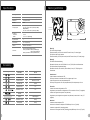
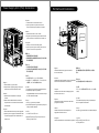
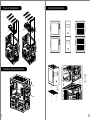
Warning and Notice
< 200mm /
7.9 inches
< 400mm / 15.7 inches
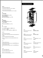
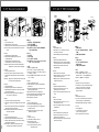
Specification
Accessory
Figure
Parts Name
Cable Tie
ODD Plate
Screw#6-32 x 6mm
Screw#6-32 x 33mm
Screw#6-32 x 15mm
Screw#6-32 x 5mm
Screw Ø5 x 10mm
PSU Rubber
Screw M3 x 6mm
Q'ty
2
4
16
4
16
2
4
4
2
Used for
Cable Management
Power
Power
Fan, Radiator
Fan
Fan
Motherboard, 3.5” HDD
2.5 HDD”
ITX Cube Case
Motherboard
Case Type
Dimension (H*W*D) 426 x 280 x 471 mm (16.8 x 11 x 18.5 inch)
Cooling System
Drive Bays
- Accessible
- Hidden
Clearance
CPU cooler height limitation: 200mm
VGA length limitation: 280mm (with ODD Cage)
400mm (without ODD Cage)
PSU length limitation: 220mm (With Bottom Fan)
Front (intake) :
120 x 120 x 25 mm Turbo fan (1000rpm, 16dBA)
Rear (exhaust) :
120 x 120 x 25 mm Turbo fan (1000rpm, 16dBA)
Stacking Gasket
2
Stacking
Stacking
Side Panel Transparent Window
Material SPCC
2 x 5.25”
4 x 3.5” or 2.5” (HDD Cage)
Expansion Slots 3
6.7” x 6.7” (Mini ITX)
I/O Port
USB 3.0 x 2, HD Audio x 1
Warning!!
CPU Cooler Height Limitation:
Please ensure that your CPU cooler does NOT exceed 200mm (7.9 inches) height.
VGA (Add-on card) Length Limitation:
Please ensure that your VGA (Add-on card) does NOT exceed 400mm (15.7 inches) length.
Warnung!!
CPU-Kühler Höhenbeschränkung:
Bitte stellen Sie sicher, dass Ihr CPU-Kühler 200 mm (7,9 Zoll) Höhe nicht überschreitet.
VGA (Add-on-Karte) Längenbeschränkung:
Bitte stellen Sie sicher, dass Ihre VGA (Add-on-Karte) 400 mm (15,7 Zoll) Länge nicht
überschreitet.
Avertissement !
Limite de hauteur du ventilateur de CPU :
Vérifiez que la hauteur du ventilateur de CPU ne dépasse pas 200 mm.
Limite de longueur de la carte (complémentaire) VGA :
Vérifiez que la longueur de votre carte (complémentaire) VGA ne dépasse pas 400 mm
Precaución
Limitación de altura del refrigerador de CPU:
Asegúrese de que la altura de su refrigerador de CPU no excede los 200 mm (7,9 pulgadas).
Limitación de longitud de la tarjeta de vídeo (adicional):
Asegúrese de que la longitud de su tarjeta de vídeo (adicional) no excede los 400 mm (15,7
pulgadas).
Attenzione!
Limitazione altezza dissipatore CPU:
Assicurarsi che l’altezza del dissipatore CPU NON superi 200 mm (7,9 pollici).
Limitazione lunghezza VGA (scheda aggiuntiva):
Assicurarsi che la lunghezza del VGA (scheda aggiuntiva) NON superi 400 mm (15,7 pollici).
藍色線條為尺寸標示,請勿印刷上去!
產品料號
C A - 1D6-00 S 1 W N - 0 0
C o r e X1
說明書
1 4 /11/25
A
產品名稱
印刷項目
發稿日期
版本
騎馬釘2 4 10 5G
雙銅
單色 無無
其他 特殊 處理 效果表面 處理
2
厚度(g/m )
裝訂 方式 材質頁數 印刷 色彩
規格 樣式
整本
CHECK DESIGN
Peipei
14.11.25
Mike.Lin
14.11.25
刀模線
125 mm
176 mm
La page est en cours de chargement...
La page est en cours de chargement...

8
9
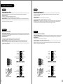
5.25" Device Installation
English /
1. Pull out the front panel.
2. Remove the 5.25” drive bay cover.
3. Slide the 5.25” device into the drive bay to lock the device.
Note: Press the 5.25” tool-free mechanism to unlock the
device.
Deutsch /
1. Ziehen Sie das Frontpanel heraus.
2. Entfernen Sie die Abdeckung des 5,25 Zoll
Laufwerksschachts.
3. Schieben Sie the 5,25 Zoll Einheit in den
Laufwerksschacht, um die Einheit zu sperren.
Anmerkung: Drücken Sie den 5,25 Zoll werkzeuglosen
Mechanismus, um die Einheit zu verriegeln.
Français /
1. Tirez le panneau de devant.
2. Enlevez le couvercle de la baie de lecteur de 5,25".
3. Faites glisser le périphérique de 5,25" dans la baie de
lecteur.
Remarque : Appuyez sur le mécanisme sans outil de 5,25"
pour déverrouiller le périphérique.
Español /
1. Tire del panel frontal.
2. Extraiga la tapa del hueco de la unidad de 5,25".
3. Meta el dispositivo de 5,25” en el hueco de la unidad
para cerrar el dispositivo.
Nota: Presione el mecanismo libre de herramienta de
5,25” para abrir el dispositivo.
Italiano /
1. Tirare verso l'esterno il pannello anteriore
2. Rimuovere il coperchio dell’alloggiamento vano unità da
5,25’’.
3. Fare scorrere il dispositivo da 5,25” nell’alloggiamento
dell’unità per bloccare il dispositivo.
Nota: Premere il meccanismo tool-free da 5,25” per
sbloccare il dispositivo.
Português/
1. Puxe o painel dianteiro para fora.
2. Remova a cobertura da baía da unidade de 5,25".
3. Deslize o dispositivo de 5,25" para a baía da unidade,
para bloquear o dispositivo.
Nota: Pressione o mecanismo de 5,25" sem utilizar
ferramentas para desbloquear o dispositivo.
繁體中文 /
1. 拉面板底部,將面板從機殼本體拆下。
2. 移除5.25”擴充槽檔板
3. 將5.25”裝置至適當的位置
注意: 如需移除5.25”裝置,先按壓5.25”無螺機機構,
再將5.25”裝置往前推出。
简体中文 /
1. 拉出前面板。
2. 移除5.25”槽盖
3. 将5.25”设备滑入驱动器槽
注意: 如需移除5.25”设备,先按压5.25”免用工具机械
装置,再将5.25”设备往前推出
日本語 /
1. 前面パネルを引き出します。
2. 5.25”ドライブベイのカバーを取り外します。
3. 5.25”デバイスをドライブベイにスライドさせてデ
バイスをロックします。
注: 5.25”工具不要メカニズムを押してデバイスをア
ンロックします。
Русский /
1. Снимите переднюю панель.
2. Снимите крышку отсека для 5,25-дюймовых
дисководов.
3. Вставьте 5,25-дюймовое устройство в отсек
дисковода для фиксации.
Примечание. Нажмите на не требующий
использования инструментов механизм отсека
для 5,25-дюймовых дисководов, чтобы
разблокировать устройство.
Türkçe /
1. Ön paneli çekerek çıkarın.
2. 5,25" sürücü bölmesi kapağını çıkarın.
3. 5,25” aygıtını kilitlemek için sürücü bölmesinin
içine doğru kaydırın.
Not: Aygıtın kilidini açmak için 5,25” araçsız
mekanizmayı bastırın.
ภาษาไทย /
1. ถอดแผงด้านหน้าออก
2. ถอดฝาปิดช่องไดรฟ์ขนาด 5.25" ออก
3. เลื่อนอุปกรณ์ขนาด 5.25"
เข้าในช่องไดร์ฟเพื่อล็อคอุปกรณ์
หมายเหตุ: กดตัวล็อคเครื่องมือขนาด 5.25"
เพื่อปลดล็อคอุปกรณ์
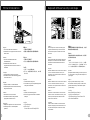
3.5" & 2.5" HDD Installation
English / 繁體中文 /
1. Pull the HDD tray out. 1. 將硬碟托盤取出
2. Place the 2.5” or 3.5” hard drive on the tray 2. 將2.5”或3.5”硬碟放置在硬碟托盤上,用螺絲固
and secure it with screws. 定硬碟
3. Slide the HDD tray back to the HDD cage. 3. 將硬碟托盤放回硬碟磁架中
Deutsch / 简体中文 /
1. Ziehen Sie den HD-Schacht heraus. 1. 将硬盘托盘取出
2. Montieren Sie die 2,5 oder 3,5 Zoll Festplatte 2. 将2.5”或3.5”硬盘放置在硬盘托盘上,
im Schacht und sichern Sie sie mit Schrauben.
用螺丝固定硬盘
3. Schieben Sie den Schacht wieder in den
3. 将硬盘托盘放回硬盘磁架中
Festplattenkäfig.
日本語 /
Français /
1.HDDトレイを引き出して外します。
1. Enlevez le boîtier du disque dur.
2.2.5インチHDD、SSD もしくは 3.5インチ
2. Placez le disque dur de 2,5” ou de 3,5” dans le
HDDドライブをトレイにネジで固定します。
boîtier et fixez-le avec des vis.
3. HDDトレイをHDDケージに戻します。
3. Refaites glisser le boîtier du disque dur dans
la cage de disques durs.
Русский /
1. Вытяните лоток для жестких дисков.
Español /
2. Установите 2,5- или 3,5-дюймовый жесткий
1. Extraiga la bandeja del disco duro.
диск в лоток и закрепите его винтами.
2. Coloque el disco duro de 2’5 ó 3'5” en la
3. Установите лоток для жестких дисков
bandeja y fíjelo con los tornillos.
обратно в каркас.
3. Vuelva a meter la bandeja del disco duro en su
hueco.
Türkçe /
1. HDD tepsisini dışarı çekin.
Italiano /
2. 2,5” veya 3,5” sabit disk sürücüsünü tepsinin
1. Estrarre il vano HDD.
üzerine yerleştirin ve vidalarla sabitleyin.
2. Posizionare il disco fisso da 2,5” o 3,5” nel
3. HDD tepsisini HDD kafesine geri yerleştirin.
vano e fissarlo con le viti.
3. Fare scorrere l’HDD indietro verso la struttura
ภาษาไทย /
a gabbia HDD.
1. ดึงถาด HDD ออกมา
2. วางฮาร์ดไดร์ฟขนาด 2.5” หรือ 3.5”
Português /
ลงบนถาดแล้วขันสกรูยึดให้แน่น
1. Puxe a bandeja do disco rígido para fora.
3. เลื่อนถาด HDD กลับเข้าในโครง HDD
2. Coloque o disco rígido de 2,5” ou 3,5” na
bandeja e fixe com parafusos.
3. Deslize a bandeja do disco rígido de volta para
a caixa do disco rígido.
3.5" HDD
2.5" HDD
Type A Type B
藍色線條為尺寸標示,請勿印刷上去!
產品料號
C A - 1D6-00 S 1 W N - 0 0
C o r e X1
說明書
1 4 /11/25
A
產品名稱
印刷項目
發稿日期
版本
騎馬釘2 4 10 5G
雙銅
單色 無無
其他 特殊 處理 效果表面 處理
2
厚度(g/m )
裝訂 方式 材質頁數 印刷 色彩
規格 樣式
整本
CHECK DESIGN
Peipei
14.11.25
Mike.Lin
14.11.25
刀模線
125 mm
176 mm

10
11
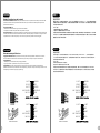
PCI Card Installation
Português /
1. Desaperte os parafusos com a chave de fendas.
2. Instale a placa PCI no local adequado e
aparafuse.
English /
1. Loosen the screws with a screwdriver.
2. Install the PCI card in proper location and secure
it with screws.
Deutsch /
1. Lösen Sie die Schrauben mit einem
Schraubendreher.
2. Installieren Sie die PCI-Card in der
vorgesehenen Position und sichern Sie sie mit
Schrauben.
Français /
1. Desserrez les vis à l’aide d’un tournevis.
2. Installez la carte PCI dans l'endroit approprié et
fixez-la avec des vis.
Español /
1. Afloje los tornillos con un destornillador.
2. Instale la tarjeta PCI en la ubicación adecuada y
asegúrela con tornillos.
Italiano /
1. Allentare le viti con un cacciavite.
2. Installare la scheda PCI nella posizione
appropriata e fissarla con le viti.
ภาษาไทย /
1. ใช้ไขควงขันสกรูออก
2. ติดตั้งการ์ด PCI
ในตำแหน่งที่เหมาะสมแล้วขันสกรูยึดให้แน่น
繁體中文 /
1. 用螺絲起子將螺絲取下.
2. 將擴充卡放置在合適的位置並用螺絲固定。
日本語 /
1.ドライバーでねじを緩めます。
2. PCI カードを適切な場所に取り付け、ねじで固
定します。
简体中文 /
1. 用螺丝起子将螺丝取下.
2. 将扩充卡放置在合适的位置并用螺丝固定。
Türkçe /
1. Vidaları, bir tornavida ile gevşetin.
2. PCI kartını uygun konuma takın ve vidalarla
sabitleyin.
Русский /
1. Ослабьте винты отверткой.
2. Установите плату PCI в надлежащий разъем
и закрепите ее винтами.
Keyboard & Mouse Security Lock Usage
English /
Deutsch /
Français /
Español /
Italiano /
Português/
Passe os cabos do teclado ou do rato através do
"Bloqueio de Segurança do Teclado e Rato" e fixe
na parte traseira do painel no interior do chassis,
com parafusos.
Place the keyboard or mouse cables through the
“Keyboard & Mouse Security Lock” then secure it
back to the back panel from inside of the chassis
with screw.
Führen Sie die Kabel durch die Einheit “Tastatur- &
Maussperren” und sichern Sie sie dann wieder an
der Rückwand innerhalb des Gehäuses mit den
Schrauben.
Mettez les câbles du clavier ou de la souris à travers
le “verrou de sécurité de clavier & souris” puis
sécurisez-les sur le panneau arrière à l'intérieur du
châssis avec des vis.
Mettez les câbles du clavier ou de la souris à travers
le “verrou de sécurité de clavier & souris” puis
sécurisez-les sur le panneau arrière à l'intérieur du
châssis avec des vis.
Posizionare i cavi della tastiera o del mouse sulla
“tastiera e il blocco di sicurezza del mouse”, quindi
fissarli sul pannello posteriore dall’interno dello
chassis con la relativa vite.
繁體中文 /
简体中文 /
日本語 /
Русский /
Türkçe /
將鍵盤或滑鼠纜線穿過「鍵盤和滑鼠安全鎖」,然後用
螺絲將其固定回機殼內的背板。
将键盘或鼠标缆线穿过“键盘和鼠标安全锁”,然后用螺
丝将其固定回机箱内侧。
「キーボードとマウスのセキュリティロック」を通し
てキーボードまたはマウスケーブルを収納し、ねじで
シャーシ内部から背面パネルに再び締め付けます。
Проведите кабели клавиатуры и мыши через зам
ок и подключите их. Закрутите замок обратно изн
утри корпуса.
Klavye veya fare kablolarını “Klavye ve Fare
Güvenlik Kilidi” üzerinden yerleştirin ve daha sonra,
güvenlik kilidini kasanın iç tarafından arka panele
yeniden vidalayın.
ภาษาไทย /
เดินสายแป้นพิมพ์หรือสายเมาส์ลอดผ่าน
“อุปกรณ์เก็บสายแป้นพิมพ์และเมาส์”
จากนั้นให้ขันสกรูยึดอุปกรณ์เก็บสายพร้อมสายเข้ากับ
แผงด้านหลังของแชสซีส์ให้แน่น
藍色線條為尺寸標示,請勿印刷上去!
產品料號
C A - 1D6-00 S 1 W N - 0 0
C o r e X1
說明書
1 4 /11/25
A
產品名稱
印刷項目
發稿日期
版本
騎馬釘2 4 10 5G
雙銅
單色 無無
其他 特殊 處理 效果表面 處理
2
厚度(g/m )
裝訂 方式 材質頁數 印刷 色彩
規格 樣式
整本
CHECK DESIGN
Peipei
14.11.25
Mike.Lin
14.11.25
刀模線
125 mm
176 mm

12
13
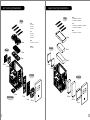
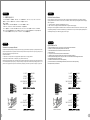
Air Cooling Installation
Top
Top
Rear
Rear
Front
Front
12cm
12cm
12cm
12cm
14cm
14cm
14cm
20cm
20cm
Liquid Cooling Installation
36cm
36cm
28cm
28cm
12cm
18cm
24cm
14cm
Bottom
Front:
3 x 120mm
2 x 140mm
1 x 200mm
Top:
3 x 120mm
2 x 140mm
2 x 200mm
Rear:
1 x 120mm or 1 x 140mm
Bottom:
1 x 120mm
Front:
1 x 120mm or 1 x 240mm
1 x 140mm or 1 x 280mm
Top:
1 x 120mm or 1 x 240mm or 1 x 360mm
1 x 140mm or 1 x 280mm
Rear:
1 x 120mm or 1 x 140mm
藍色線條為尺寸標示,請勿印刷上去!
產品料號
C A - 1D6-00 S 1 W N - 0 0
C o r e X1
說明書
1 4 /11/25
A
產品名稱
印刷項目
發稿日期
版本
騎馬釘2 4 10 5G
雙銅
單色 無無
其他 特殊 處理 效果表面 處理
2
厚度(g/m )
裝訂 方式 材質頁數 印刷 色彩
規格 樣式
整本
CHECK DESIGN
Peipei
14.11.25
Mike.Lin
14.11.25
刀模線
125 mm
176 mm

14
15
Bracket Installation
I/O Panel Placement Guide
12cm
20cm
A
B
Stacking Installation
x 4
x 4
+
藍色線條為尺寸標示,請勿印刷上去!
產品料號
C A - 1D6-00 S 1 W N - 0 0
C o r e X1
說明書
1 4 /11/25
A
產品名稱
印刷項目
發稿日期
版本
騎馬釘2 4 10 5G
雙銅
單色 無無
其他 特殊 處理 效果表面 處理
2
厚度(g/m )
裝訂 方式 材質頁數 印刷 色彩
規格 樣式
整本
CHECK DESIGN
Peipei
14.11.25
Mike.Lin
14.11.25
刀模線
125 mm
176 mm

16 17
Leads Installation Guide
Case LED Connection / On the front of the case, you can find some LEDs and switch leads. Please consult your user
manual of your motherboard manufacturer, then connect these leads to the panel header on the motherboard.
USB 3.0 connection /
1. Make sure your motherboard supports USB 3.0 connection.
2. Connect the USB 3.0 cable to the available USB 3.0 port on your computer.
Audio Connection / Please refer to the following illustration of Audio connector and your motherboard user manual.
Please select the motherboard which used AC’97 or HD Audio(Azalia),(be aware of that your audio supports AC’97 or HD
Audio (Azalia)) or it will damage your device(s).
Anschlüsse herstellen
Gehäuse-LED-Verbindungen / Auf der Gehäusevorderseite finden Sie einige LEDs und Verbindungen. Bitte nehmen
Sie die Gebrauchsanweisung Ihres Motherboard Herstellers zur Hilfe und schließen Sie diese Verbindungen an die Panel
Header Belegung des Motherboards an.
USB 3.0 Anschluss /
1. Stellen Sie sicher, dass Ihre Hauptplatine den USB 3.0 Anschluss unterstützt.
2. Verbinden Sie das USB 3.0 Kabel mit dem USB 3.0 Port auf Ihrem Computer.
Audio Anschlüsse / Bitte beachten Sie die folgende Abbildung der Audio Anschlüsse und die Anweisung in der
Gebrauchsanweisung Ihres Motherboards. Bitte wählen Sie das Motherboard, das AC’97 oder HD Audio(Azalia)
verwendet, (achten Sie darauf, dass Ihr Audio AC’97 bzw. HD Audio (Azalia unterstützt)). Andernfalls entstehen schwere
Schäden an Ihrem(n) Gerät(en)!!!
Leads Installation
English
Deutsch
USB 3.0 Connection
L-OUT
SENSE
R-OUT
MIC-POWER
MIC-IN
SENSE2
KEY
SENSE1
PRESENSE
GND
L-OUT
R-OUT
MIC-POWER
MIC-IN
L-RET
KEY
R-RET
GND
Guide d'installation des fils
Connexion des voyants du boîtier / Sur la face avant du boîtier, vous trouverez plusieurs voyants et les fils des
boutons. S'il vous plaît consultez le guide d'utilisateur du fabricant de votre carte mère, puis connectez ces fils aux
onnecteurs sur la carte mère.
Connexion USB 3.0 /
1. Vérifiez que votre carte mère prend en charge la connexion USB 3.0.
2. Connectez le câble USB 3.0 au port USB 3.0 disponible sur votre ordinateur.
Connexion Audio / S'il vous plaît référez vous à l'illustration suivante du connecteur audio et au guide de l'utilisateur de
votre carte mère. S'il vous plaît sélectionnez une carte mère supportant AC'97 ou HD Audi (Azalia), (faites attention que
votre audio supporte l'AC'97 ou HD Audio (Azalia)) sinon cela pourrait endommager votre matériel.
Guía de Instalación de Cables
Conexión del LED de la caja / En la parte frontal de la caja, encontrará algunos LED y cables de interruptores. Consulte
el manual del usuario del fabricante de la placa madre, a continuación conecte estos cables al conector de la placa madre.
Conexión USB 3.0 /
1. Asegúrese de que la placa base admite conexión USB 3.0.
2. Conecte el cable USB 3.0 al puerto USB 3.0 disponible en el equipo.
Conexión de Audio / Consulte la siguiente ilustración del conector de Audio y el manual del usuario de la placa madre.
Seleccione la placa madre que utiliza AC’97 o HD Audio (Azalia), (asegúrese de que su audio admite AC’97 o HD Audio
(Azalia)) si no, sus dispositivos resultarán dañados
USB 3.0 Connection
L-OUT
SENSE
R-OUT
MIC-POWER
MIC-IN
SENSE2
KEY
SENSE1
PRESENSE
GND
L-OUT
R-OUT
MIC-POWER
MIC-IN
L-RET
KEY
R-RET
GND
Français
Español
藍色線條為尺寸標示,請勿印刷上去!
產品料號
C A - 1D6-00 S 1 W N - 0 0
C o r e X1
說明書
1 4 /11/25
A
產品名稱
印刷項目
發稿日期
版本
騎馬釘2 4 10 5G
雙銅
單色 無無
其他 特殊 處理 效果表面 處理
2
厚度(g/m )
裝訂 方式 材質頁數 印刷 色彩
規格 樣式
整本
CHECK DESIGN
Peipei
14.11.25
Mike.Lin
14.11.25
刀模線
125 mm
176 mm
La page est en cours de chargement...
La page est en cours de chargement...
-
 1
1
-
 2
2
-
 3
3
-
 4
4
-
 5
5
-
 6
6
-
 7
7
-
 8
8
-
 9
9
-
 10
10
-
 11
11
-
 12
12


Thermaltake Core X1 Manuel utilisateur
- Catégorie
- Boîtiers d'ordinateurs
- Taper
- Manuel utilisateur
dans d''autres langues
- italiano: Thermaltake Core X1 Manuale utente
- English: Thermaltake Core X1 User manual
- español: Thermaltake Core X1 Manual de usuario
- Deutsch: Thermaltake Core X1 Benutzerhandbuch
- русский: Thermaltake Core X1 Руководство пользователя
- português: Thermaltake Core X1 Manual do usuário
- eesti: Thermaltake Core X1 Kasutusjuhend
- 日本語: Thermaltake Core X1 ユーザーマニュアル
- Türkçe: Thermaltake Core X1 Kullanım kılavuzu
Documents connexes
-
Thermaltake Versa H35 Manuel utilisateur
-
-
Thermaltake suppressor f31 Manuel utilisateur
-
Thermaltake core x71 Manuel utilisateur
-
Thermaltake Suppressor F51 Manuel utilisateur
-
-
-
-
-