
Installation guide
flowIQ® 4200 - US
Kamstrup Water Metering, LLC · 245 Hembree Park Drive, Ste. 110 · Roswell, GA 30076, USA · in[email protected]

2Kamstrup A/S • 55123307_A1_EN-US_06.2022
Installation guide flowIQ® 4200
Contents
1 In general 3
1.1 Intended use and installation scenarios 3
2 Lids 4
3 Installation requirements 5
3.1 In general 5
3.2 Installation precautions 5
3.3 Operating pressure 5
3.4 Flow direction 6
4 flowIQ® 4200 installation 6
4.1 Sediments in the water 7
4.2 ‘Spool piece installation (only applies to 6” and 8” meters) 7
4.3 Split flange installation 8
4.3.1 General flange features and specifications 9
4.3.2 Criss-cross pattern 10
4.3.3 Installing the split flanges on the meter first 10
4.3.4 Installing the flange on the pipeline first 11
4.4 Installation angle 12
4.5 Straight inlet 12
4.6 Flow disturbance and flow cavitation 12
4.6.1 Service connection 12
5 FCC Cautions 13
6 ICES/ISED cautions 14

3Kamstrup A/S • 55123307_A1_EN-US_06.2022
Installation guide flowIQ® 4200
1 In general
Please read this guide carefully before installing Kamstrup water meters.
flowIQ® 4200 meters are used for measuring potable water and all variants are built for
submerged conditions.
All meters have an arrow on the side of the meter body, indicating the correct flow
direction through the meter.
Restrictions:
• Ensure that the meter is mounted in the correct flow direction
• Ensure correct operating pressure
• Avoid placing the meter in direct sunlight. For meters subjected to any kind of
mechanical impact, it is recommended to install a lid on the meter
1.1 Intended use and installation scenarios
flowIQ® 4200 meters are intended for measurements of cold water consumption in
industrial environments such as distribution networks and commercial buildings.
Installation scenarios can be in submerged conditions as well.
Ambient temperature range: 35-130 °F.
Disclaimer: In case of reasonably foreseeable misuse or incorrect mounting,
Kamstrup´s warranty obligations no longer apply.

4Kamstrup A/S • 55123307_A1_EN-US_06.2022
Installation guide flowIQ® 4200
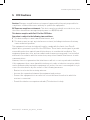
flowIQ® 4200 is suitable for mounting in well applications.
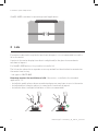
2 Lids
For meters subjected to any kind of mechanical impact, it is recommended to install a
lid on the meter.
It protects the meter display from direct sunlight and/or the glass from moderate
mechanical impact.
For flowIQ® 4200 meters, it is possible to install a lid.
The lid can be ordered as a separate accessory and will not be attached or mounted on
the meter from factory.
- Lid: type no: 66-99-645
Kamstrup requires the installation of a lid if the meter – installed in the intended
application – is:
• Installed in public places where unauthorized persons may have access to the meter
• Installed where it may be subject to some kind of mechanical impact
• Installed in direct sunlight (installation of lid is recommended)

5Kamstrup A/S • 55123307_A1_EN-US_06.2022
Installation guide flowIQ® 4200
3 Installation requirements
3.1 In general
When installing the meter, it must be orientated correctly in relation to flow direction:
• The flow direction is indicated by an arrow on the side of the meter
• The meter ought to be orientated so that the display is easy to read
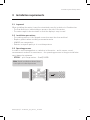
3.2 Installation precautions
• The sealing surface of the flanged connection must be clean and level
• Replace gaskets when installing a new water meter
• ALWAYS use new gaskets
• Gaskets in original quality is of crucial importance
3.3 Operating pressure
In order to avoid entrapped air or cavitation in the meter – and to ensure correct
measurement under all circumstances – the operating pressure in the pipe installation
must always be minimum:
• 275 PSI – split flange meters – flowIQ® 4200
Note: Avoid installation where there
is no option for back pressure

6Kamstrup A/S • 55123307_A1_EN-US_06.2022
Installation guide flowIQ® 4200
3.4 Flow direction
The meter has an arrow on the side of the meter, indicating the right flow direction
through the meter. Only this direction is legal. If flow is registered in the wrong direction,
the info code ‘REVERSE’ is visible in the display, which means that the meter detects
reverse flow. The meter calculates the volume in a separate register not verified for
billing. Reverse volume is NOT displayed on the meter.
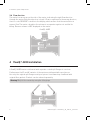
4 flowIQ® 4200 installation
A flowIQ® 4200 meter is delivered with separate coated split flanges in cast iron.
Furthermore the 6” and 8” variants of the meter are delivered with spool pieces.
Use only the original split flanges and spool pieces from Kamstrup combined with
original fiber gaskets. Gaskets can be ordered separately.
flowIQ® 4200
Warning! Only lift the meter by using the lifting lugs.

7Kamstrup A/S • 55123307_A1_EN-US_06.2022
Installation guide flowIQ® 4200
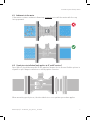
4.1 Sediments in the water
If the water contains sediments Kamstrup suggests to install the meter with the cup
facing upwards.
4.2 ‘Spool piece installation (only applies to 6” and 8” meters)
Spool pieces should be mounted on the pipeline flanges first to ensure flexible options in
regards to split flange installation on either pipeline or meter.
When mounting spool pieces, the described criss-cross pattern procedure applies.

8Kamstrup A/S • 55123307_A1_EN-US_06.2022
Installation guide flowIQ® 4200
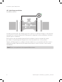
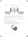
4.3 Split flange installation
Installation sketch:
Installing a meter with split flanges gives the option to install the flanges on the pipeline
systems first or on the meter itself. Best practice depends on the installation scenarios
and the space conditions.
Both options are described below and both installation options require the same
procedure for tightening the flange bolts in the described criss-cross pattern.
Tighten all flange bolts according to the described criss-cross pattern with the correct
tightening torque. Repeat this procedure three times in total to ensure correct meter
installation.
Note! Criss-cross pattern to be repeated three times.

9Kamstrup A/S • 55123307_A1_EN-US_06.2022
Installation guide flowIQ® 4200
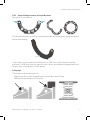
4.3.1 General flange features and specifications
Fixing bolt ¼” bolt and nut:
The fixing bolt thread is useful for connecting the two split flange parts during installation.
Pushing nut milling:
If extra space for the gasket is needed, insert a 7/16” nut in the pushing nut milling,
and insert a 7/16” bolt from the opposite side to press and enlarge the gap between the
flanges, thus creating space for the gasket.
Lifting lugs
The lifting lugs have two purposes:
• Supporting safe conduct regarding meter installation when lifting
• Fixating the split flanges on the meter

10 Kamstrup A/S • 55123307_A1_EN-US_06.2022
Installation guide flowIQ® 4200
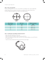
4.3.2 Criss-cross pattern
Tighten all flange bolts in a criss-cross pattern according to the correct tightening
torque. Repeat this procedure three times according to the torque table below.
Follow the tightening pattern as shown in the figures below:
4.3.3 Installing the split flanges on the meter first
• Place the meter vertically on one end
• Fixate the two split flanges together by using a ¼” bolt
• Place the flange around the meter and close the flange by fixing a second ¼” bolt in
the opposite side
• Turn the meter upside down and install the other split flange
Meter flange
Meter size
Bolt size
inch
Tightening torque
PN16
6” 3/4” 180 ft x lbs
8” 3/4” 180 ft x lbs
10” 7/8” 250 ft x lbs
12” 7/8” 250 ft x lbs
8-bolt
1
2
3
45
6
7
8
12-bolt
1
2
3
4
11
12
5
10
67
8
9

11Kamstrup A/S • 55123307_A1_EN-US_06.2022
Installation guide flowIQ® 4200
• Lift the meter via the two lifting lugs and lower the meter into place
• Mount the two lowest bolts and nuts on each of the two flanges to the pipeline flanges
• Place the new gasket between the meter flanges and the pipeline flanges
• Pre-tighten the remaining bolts and nuts
• Tighten the bolts in the described criss-cross pattern and with the correct tightening
torque mentioned in the table
• Repeat the sequence three times to ensure that all bolts are tightened with the correct
torque
4.3.4 Installing the flange on the pipeline first
• Fixate the two split flanges by using a ¼” bolt
• Place the below part of the split flange on the below part of the pipeline flange by
fixating the two lowest bolts first as shown in the figure below
• Insert the gasket between the flange and the pipeline flange

12 Kamstrup A/S • 55123307_A1_EN-US_06.2022
Installation guide flowIQ® 4200
• Repeat the same procedure on the opposite pipeline flange
• Lift the meter via the two lifting lugs and lower the meter into place
• Pre-tighten the remaining bolts and nuts
• Tighten the bolts in the described criss-cross pattern and with the correct tightening
torque mentioned in the table
• Repeat the sequence three times to ensure that all bolts are tightened with the correct
torque
4.4 Installation angle
For flowIQ® 4200, it applies that the meter can be mounted at all angles and in all
positions.
However, it is recommended to mount the display in such a way that it is easy to read.
4.5 Straight inlet
Normally, the meter requires neither straight inlet nor straight outlet to achieve accurate
measurement. However, for installation environments with heavy flow disruptions,
several lengths of straight inlets are advisable. This applies to all flange meters.
4.6 Flow disturbance and flow cavitation
The components mentioned below can generate heavy flow disruptions or pressure drops:
• Butterfly valve
• Pressure- and flow-regulated components
• Partially closed ball valve
• Pumps in front of the meter
• Pumps after the meter
• Double conjugation in several directions
4.6.1 Service connection
When the meter has been mounted in the system, neither welding nor freezing is
allowed. The meter must be dismounted from the system before starting such work.
If the electrical service in the building has been grounded via the plumbing, it must be
ensured that adequate electrical ground is maintained both during and after installation.
In order to facilitate replacement of the meter, closing valves should be mounted on
both sides of the meter. Under normal operating conditions, a strainer is not required in
front of the meter.
Note! To enlarge the gasket gap, utilize the pushing nut milling with a bolt and a nut.
Note! Cavitation affects the measurement accuracy and may physically damage the meter.

13Kamstrup A/S • 55123307_A1_EN-US_06.2022
Installation guide flowIQ® 4200
5 FCC Cautions
Caution: Changes or modifications not expressly approved by the party responsible for
compliance could void the users authority to operate the equipment.
RF Exposure compliance statement: This device may be used with no restrictions, since
the source-based time-averaged output power is ≤ 60/f(GHz) mW.
This device complies with Part 15 of the FCC Rules.
Operation is subject to the following two conditions:
1 This device may not cause harmful interference, and
2 This device must accept any interference recieved, including interference that may
cause undesired operation.
This equipment has been tested and found to comply with the limits for a Class B
digital device, pursuant to part 15 of the FCC Rules. These limits are designed to provide
reasonable protection against harmful interference in a residential installation. This
equipment generates, uses and can radiate radio frequency energy and, if not installed
and used in accordance with the instructions, may cause harmful interference to radio
communications.
However, there is no guarantee that interference will not occur in a particular installation.
If this equipment does cause harmful interference to radio or television reception, which
can be determined by turning the equipment off and on, the user is encouraged to try to
correct the interference by one or more of the following measures:
- Reorient or relocate the receiving antenna.
- Increase the separation between the equipment and receiver.
- Connect the equipment into an outlet on a circuit different from that to which the
receiver is connected.
- Consult the dealer or an experienced radio/TV technician for help.

14 Kamstrup A/S • 55123307_A1_EN-US_06.2022
Installation guide flowIQ® 4200
6 ICES/ISED cautions
English:
This device complies with Industry Canada license-exempt RSS standard(s). Operation is
subject to the following two conditions:
(1) This device may not cause interference, and
(2) This device must accept any interference, including interference that may cause
undesired operation of the device.
Complies with the Canadian ICES-003 Class B specifications.
This device complies with RSS 247 of Industry Canada. This Class B device meets all the
requirements of the Canadian interference-causing equipment regulations.
This radio transmitter IC ID 22376-KWM4220 has been approved by Innovation, Science
and Economic Development Canada to operate with the antenna types listed below, with
the maximum permissible gain indicated. Antenna types not included in this list that
have a gain greater than the maximum gain indicated for any type listed are strictly
prohibited for use with this device.
This equipment has been approved for fixed operation, and unless otherwise advised
in separate supplemental instructions for individual wireless transmitter(s), requires
minimum 25 cm spacing be provided between antenna(s) and all person’s body
(excluding extremities of hands, wrist and feet) during wireless modes of operation.
Maximum gain:
Antenna type 450-470 MHz: 902-928 MHz:
Helix -2.9 dBi -2.1 dBi
PIt, small -5.3 dBi 1.2 dBi
Wall 0.5 dBi -1.6 dBi
Must be installed to provide a separation distance of at least 25 cm from all persons.

15Kamstrup A/S • 55123307_A1_EN-US_06.2022
Installation guide flowIQ® 4200
Must be installed to provide a separation distance of at least 25 cm from all persons.
Doit être installé de façon à respecter une distance de minimum 25 cm à toute personne.
Français:
Cet appareil est conforme aux normes CNR exemptes de licence d’Industrie Canada. Le
fonctionnement est soumis aux deux conditions suivantes:
(1) Cet appareil ne doit pas provoquer d’interférences et
(2) Cet appareil doit accepter toute interférence, y compris celles susceptibles de
provoquer un fonctionnement non souhaité de l’appareil.
Cet appareil numérique de la classe B est conforme à la norme NMB-003 du Canada.
Cet appareil est conforme à la norme canadienne RSS 247. Cet appareil numérique de
la Classe B respecte toutes les exigences du Règlement sur le matériel brouilleur du
Canada.
Cet émetteur radio IC ID 22376-KWM4220 a été approuvé par Innovation, Sciences et
Développement économique Canada pour fonctionner avec les types d’antenne
énumérés cidessous, avec le gain maximal autorisé indiqué. Les types d’antenne non
inclus dans cette liste et ayant un gain supérieur au gain maximum indiqué pour tout
type répertorié sont strictement interdits pour l’utilisation avec cet appareil.
Cet équipement a été approuvé pour une utilisation fixe et, sauf indication contraire dans
les instructions supplémentaires pour émetteurs sans fil individuels, cet équipement
nécessite un espace minimum de 25 cm entre l’antenne (s) et le corps de la personne
utilisant l´appareil (à l’exclusion des extrémités des mains, des poignets et des pieds)
pendant les modes de fonctionnement sans fil.
Maximum gain:
Antenna type 450-470 MHz: 902-928 MHz:
Helix -2.9 dBi -2.1 dBi
PIt, small -5.3 dBi 1.2 dBi
Wall 0.5 dBi -1.6 dBi

16 Kamstrup A/S • 55123307_A1_EN-US_06.2022
Installation guide flowIQ® 4200
-
 1
1
-
 2
2
-
 3
3
-
 4
4
-
 5
5
-
 6
6
-
 7
7
-
 8
8
-
 9
9
-
 10
10
-
 11
11
-
 12
12
-
 13
13
-
 14
14
-
 15
15
-
 16
16


