PolyVision Frameless Flow Guide d'installation
- Taper
- Guide d'installation

a3™ CeramicSteel Flow™
Frameless Application
Installation Guide
Guidelines for installing your new
a3 CeramicSteel Frameless Flow
EMEA 2019
English
Français
Deutsch
Doc # 143842 | Rev A | Page 1 of 38

3 Safety Requirements
4 Handling + Storing of Panels
5 Required Materials + Equipment
6 1830 Vertical Wall Bracket Positioning
7 2420 Vertical Wall Bracket Positioning
8 1830 Horizontal Wall Bracket Positioning
9 2420 Horizontal Wall Bracket Positioning
13 Warranty
English
a3 CeramicSteel Frameless Flow - Wall Mounted
Dry Erase Board, Non-Seismic Applications
Safety Requirements
Minimum Required Wall Construction
Drywall with metal studs:
• Must be at least 0.6 mm (.02") thick Metal
stud 48.8 mm x 50 mm (1.92" x 1.97")
• Studs on maximum 600 mm (24") centers
• Must be at least 2 x 12,5 mm (.49") Type X
gypsum drywall
• 35 mm (1.34") drywall screws on 250 mm
(12") centers
Verify Wall Construction
CAUTION! Adequate wall construction is
required to support the weight of the board.
Minimum wall construction must be capable
of supporting weight amounts listed in Table
1 on page 4.
The building’s Engineer of Record must be
consulted to determine if there are any seismic
requirements.
Drywall with wooden studs:
• Stud grade SPF, DFL or Hem-Fir 45 mm
x 70 mm (1.5” x 3.5”)
• Studs on 600 mm (24”) centers
• Must be atleast 25 mm (5/8”) thick Type X
gypsum drywall for the US or 2 x 12,5 mm (1/2”)
for EU
• 35 mm (#6 x 11/4”) drywall screws on 250 mm
(12”) centers
Doc # 143842 | Rev A | Page 3 of 38 Doc # 143842 | Rev A | Page 2 of 38

Handling + Storing of Panels
Handling
• When a3 CeramicSteel panels are shipped, they
are protected by craft paper or a self-adhesive
transparent polyethylene ilm. Keep panels in the
original package until installation.
• Handle with care to prevent damage.
• Never slide panels o the stack during handling.
Panels should always be lifted and moved in a
vertical position.
• Never place an a3 panel in a vertical position on
the loor. This is to prevent damage to the edges.
• Prevent dirt from settling on and between panels
to avoid surface damage, scratches or defects.
• Follow all safety instructions regarding personal
protection when processing the panels.
• Protect panel surface against sawdust and
sparks (metal particles).
• a3 CeramicSteel will chip when cut or drilled with
power tools. Hand-cutting can cause chipping
up to approx. 2 mm from the edge. When
chipping is in excess of 2 mm, please check the
state of cutting tools and check that the panel is
adequately supported and clamped to prevent it
from vibrating.
• All cut or drilled sections should be protected
against humidity with PVC tape and/or by
covering/sealing proiles or sealing washers.
• For detailed processing instructions, please refer
to the a3 processing instructions.
Storing
• Keep panels dry and free of debris.
• Store panels inside temps 5090 °F (1032 °C).
• Any panels stored outside should be protected
from inclement weather conditions.
• Place panels on hard, lat surfaces that are not
subject to standing water.
• a3 CeramicSteel panels should be stacked no
more than three high.
• Panels should never be stored vertically or in
such a way that the corners are vulnerable to
damage.
If you have a problem, question, or a request, call
your local fabricator, your regional sales manager
or PolyVision Customer Service. PolyVision’s global
customer service team can be contacted on
polyvision.com.
Table 1 Horizontal Installation
Product Weight (kg/lb)/panel
Frameless Flow 1830 28 kg / 61.73 lb
Frameless Flow 2420 37 kg / 81.57 lb
• Drill
• #2 Bit
• Glass suction cup lifters (2)
• Pliers
• Pencil
• Level or laser
• 2 or 3-step ladder
• Tape measure
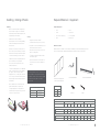
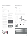
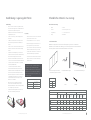
Required Materials + Equipment
Required Equipment
Materials Provided
NOTE: Items are not drawn to scale. Quantity of wall anchors and screws will vary per product
due to the various widths. Board size determines the quantity of anchors and screws.*
Horizontal wall bracketsVertical wall brackets
Horizontal oriented panels
or vertical oriented panels
Anchors Screws
Table 2
Product Panel A (right) Panel B (intermediate) Panel C (left)
# Vertical
Brackets
# Horizontal
Brackets
# Screws/
Anchors
# Vertical
Brackets
# Horizontal
Brackets
# Screws/
Anchors
# Vertical
Brackets
# Horizontal
Brackets
# Screws/
Anchors
Vertical Frameless Flow
Frameless Flow 1830 1 2 17 1 2 17 0 2 10
Frameless Flow 2420 1 3 24 1 3 24 0 3 15
Horizontal Frameless Flow
Frameless Flow 1830 1 2 15 1 2 15 0 2 10
Frameless Flow 2420 1 2 25 1 2 25 0 2 20
Frameless Flow Panels
Panel A Right
Panel B Intermediate
Panel C Left
Doc # 143842 | Rev A | Page 5 of 38 Doc # 143842 | Rev A | Page 4 of 38

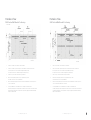
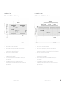
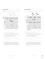
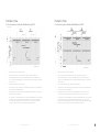
Frameless Flow
1830 Vertical Wall Bracket Positioning
1. Deine the centerline of the Frameless Flow installation
2. Deine the centerline of panel A and panel C. This will be the centerline of the brackets.
If uneven panels: from center of wall left and right 1185 mm (465/8").
If even panel: from center of wall left and right 592.5 mm (235/16").
3. Deine the top of the wall to install from the ground level.
4. Measure 220 mm (811/16") down from top of predeined top of wall.
This mark is the bottom of the top wall bracket
5. Measure 1515 mm (595/8") down from the irst horizontal wall bracket to deine the position
of the second bracket.
6. Use the predrilled holes of the wall bracket as a template to mark all the holes.
Pre-drill 6,5 mm (1/4") hole in the drywall. Insert all anchors into the holes and screw them lush.
Fix all the brackets. Make sure the top brackets are perfectly aligned, leveled and ixed irmly.
Repeat for all the brackets.
Frontview
Frameless Flow
2420 Vertical Wall Bracket Positioning
1. Deine the centerline of the Frameless Flow installation
2. Deine the centerline of panel A and panel C. This will be the centerline of the brackets.
If uneven panels: from center of wall left and right 1185 mm (465/8").
If even panel: from center of wall left and right 592,5 mm (235/16")
3. Deine the top of the wall to install from the ground level.
4. Measure 220 mm (811/16") down from top of predeined top of wall.
This mark is the bottom of the top wall bracket
5. Measure 1065 mm (4115/16") down from the irst horizontal wall bracket to deine the position
of the second and 2105 mm down to the third.
6. Use the predrilled holes of the wall bracket as a template to mark all the holes.
Pre-drill 6,5 mm (1/4") hole in the drywall. Insert all anchors into the holes and screw them lush.
Fix all the brackets. Make sure the top brackets are perfectly aligned, leveled and ixed irmly.
Repeat for all the brackets.
Frontview
Doc # 143842 | Rev A | Page 7 of 38 Doc # 143842 | Rev A | Page 6 of 38

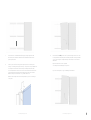
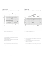
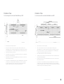
Frameless Flow
1830 Horizontal Wall Bracket Positioning
1. Deine the centerline of the Frameless Flow installation
2. Deine the centerline of panel A and panel C. This will be the centerline of the brackets.
If uneven panels: from center of wall left and right 1830 mm (72").
If even panel: from center of wall left and right 915 mm (36")
3. Deine the top of the wall to install from the ground level.
4. Measure 220 mm (811/16") down from top of predeined top of wall.
This mark is the bottom of the top wall bracket
5. Measure 870 mm (341/4") down from the irst horizontal wall bracket to deine the position
of the second bracket.
6. Use the predrilled holes of the wall bracket as a template to mark all the holes.
Pre-drill 6,5 mm (1/4") hole in the drywall. Insert all anchors into the holes and screw them lush.
Fix all the brackets. Make sure the top brackets are perfectly aligned, leveled and ixed irmly.
Repeat for all the brackets.
Frontview
Frameless Flow
2420 Horizontal Wall Bracket Positioning
1. Deine the centerline of the Frameless Flow installation
2. Deine the centerline of panel A and panel B/C. This will be the centerline of the brackets.
If uneven panels: from center of wall left and right 550 mm (215/8") + 1320 mm (5115/16") +
1100 mm (435/16"). If even panel: from center of wall left and right 660 mm (26") + 1100 mm (425/16").
3. Deine the top of the wall to install from the ground level.
4. Measure 220 mm (811/16") down from top of predeined top of wall.
This mark is the bottom of the top wall bracket
5. Measure 870 mm (341/4") down from the irst horizontal wall bracket to deine the position
of the second bracket.
6. Use the predrilled holes of the wall bracket as a template to mark all the holes.
Pre-drill 6,5 mm (1/4") hole in the drywall. Insert all anchors into the holes and screw them lush.
Fix all the brackets. Make sure the top brackets are perfectly aligned, leveled and ixed irmly.
Repeat for all the brackets.
Frontview
Doc # 143842 | Rev A | Page 8 of 38 Doc # 143842 | Rev A | Page 9 of 38

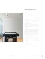
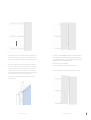
7. Place Panel A onto the wall brackets by lifting it up, holding it against the wall
above the brackets and slide it downwards in the wall brackets. Make sure the
panel is perfectly level.
8. Clean the groove before inserting the vertical proile. Insert the vertical proile
in the groove starting 10 mm (3/8") from the top of the panel. Use the pre-drilled holes
as a template to mark the holes. Remove the proile and pre-drill 6,5 mm (1/4")
hole in the drywall. Insert anchors into the holes and screw them lush. Reinsert the
vertical proile and ix the proile at the area where the proile touches the wall.
Make sure the proile is ixed at least on top, middle and bottom.
Make sure the vertical proile is inserted completely in the groove over the length
of the panel.
10. Place Panel B/C: carefully insert bottom of panel at an angle at the bottom corner.
Let the panel slide towards the previous installed panel, make sure the panels make
contact over the length of the panel and snap it down irmly onto the horizontal
wall bracket.
Repeat as many times as there is a panel B.
Once all B panels are installed, repeat for panel C
Tip: To remove the panel, use opposite handling from installation.
Doc # 143842 | Rev A | Page 11 of 38 Doc # 143842 | Rev A | Page 10 of 38

©2019 PolyVision Corporation. All rights reserved. Trademarks used herein are the trademarks of PolyVision
Corporation or their respective owner. PolyVision Corporation reserves the right to make changes in
product design, construction or detail, and to discontinue any product or material without notice.
polyvision.com 07-31-19 ENG
CeramicSteel Surface: Forever warranty
PolyVision warrants that all porcelain-enameled surfaces and/or products made with
e3™ CeramicSteel (Premium Writing Surfaces) or a3™ CeramicSteel (Collaborative Products)
will retain its writing and erasing qualities and maintain its gloss variance and color
consistency for the life of the building or for as long as the product is in use, whichever
comes irst.
Panel Construction: 10 year limited warranty
PolyVision warrants that our panels, under normal atmospheric conditions and when sealed
from moisture, will not delaminate from the substrate or warp for a period of 10 years.
Accessories: 2 year limited warranty
PolyVision warrants that our accessories, including but not limited to Collaborative ToolBar
and round magnetic eraser, when used under normal conditions will perform as intended
for a period of 2 years. Consumables like markers and chalk sticks are not covered by the
Accessories warranty.
Should any failure to conform to this warranty become apparent, then, upon written notice
from the customer, PolyVision, at its option, will correct such nonconformity by repair or
replacement. Correction in the manner provided above shall constitute a fulillment of
all liabilities of PolyVision with respect to the quality of the CeramicSteel. The warranty is
applicable only under normal usage and maintenance and does not cover defects caused
by improper handling, vandalism or abuse, or arising from failure to follow PolyVision’s
instructions and recommendations for maintenance.
The warranty is voided if any modiications are made to the products by the customer or
other trades with or without PolyVision’s written consent or prior knowledge. The warranty
does not include the cost of removal or reinstallation. This warranty is eective as of July 12,
2019, and supersedes the terms and conditions of all prior surface warranties issued to the
customer by PolyVision.
This limited warranty is the sole remedy for product defects and no other express or
implied warranty is provided, including but not limited to any implied warranties of
merchantability or itness for a particular purpose. PolyVision shall not be liable for
consequential or incidental damages arising from any product defect.
Collaborative Products Warranty
Doc # 143842 | Rev A | Page 13 of 38 Doc # 143842 | Rev A | Page 12 of 38

3 Exigences de sécurité
4 Manipulation et stockage des panneaux
5 Matériel et équipements requis
6 Positionnement des supports de ixation muraux verticaux 1830
7 Positionnement des supports de ixation muraux verticaux 2420
8 Positionnement des supports de ixation muraux horizontaux 1830
9 Positionnement des supports de ixation muraux horizontaux 2420
13 Garantie
Français
CeramicSteelFlowa3 sans cadre – Panneau
eaçable à sec monté sur le mur, applications
non sismiques
Exigences de sécurité
Construction de mur minimale requise
Une cloison sèche dotée de montants métalliques:
• doit faire au moins 0,6mm d’épaisseur,
montants métalliques de 48,8mm x 50mm
• les montants doivent avoir des diamètres de
600mm maximum
• doit être une cloison en gypse de typeX de
2 x 12,5mm
• vis pour cloisons sèches de 35mm à des
diamètres de 250mm
Vériication de la construction du mur
ATTENTION! Un mur construit de manière
appropriée est requis pour supporter le
poids du panneau. Une construction de mur
minimale doit pouvoir supporter les poids
répertoriés dans le tableau1 de la page4.
L’ingénieur responsable du projet du bâtiment
doit être consulté pour déterminer les
éventuelles exigences sismiques.
Cloison sèche dotée de montants en bois:
• montant de catégorie EPS, douglas ou mélèze
ou pruche sapin de 45mmx70mm
• les montants doivent avoir des diamètres de
600mm
• doit être une cloison en gypse de typeX de
25mm d’épaisseur pour les États-Unis ou de
2 x 12,5mm d’épaisseur pour l’Union
européenne
• 6vis pour cloisons sèches de 35mm à des
diamètres de 250mm
Doc # 143842 | Rev A | Page 15 of 38 Doc # 143842 | Rev A | Page 14 of 38

Manipulation et stockage des panneaux
Manipulation
• Lors de leur envoi, les panneaux CeramicSteela3
sont protégés par du papier kraft ou un ilm en
polyéthylène transparent autoadhésif. Conservez
les panneaux dans leur emballage d’origine
jusqu’à leur installation.
• Manipulez-les avec précaution pour éviter de les
endommager.
• Ne tirez jamais les panneaux en les faisant
glisser hors de la pile lors de la manipulation.
Les panneaux doivent toujours être soulevés et
déplacés en position verticale.
• Ne placez jamais un panneau a3 en position
verticale sur le sol. Cela évite d’endommager les
bords.
• Évitez que la saleté s’installe sur les panneaux ou
entre ceux-ci ain d’éviter l’endommagement du
revêtement, l’apparition de rayures ou de défauts.
• Suivez toutes les instructions de sécurité
relatives à la protection personnelle lors de la
manutention des panneaux.
• Protégez le revêtement des panneaux des
sciures et des étincelles (particules métalliques).
• Les panneaux CeramicSteela3 peuvent
s’ébrécher quand ils sont découpés ou percés
avec des outils électriques. La découpe à la
main peut ébrécher le panneau à environ 2mm
maximum du bord. Quand l’ébrèchement est
supérieur à 2mm, vériiez l’état des outils de
coupe et assurez-vous que le panneau est
correctement soutenu et ixé pour éviter qu’il ne
vibre.
• Toutes les parties découpées ou percées
doivent être protégées contre l’humidité avec
de l’adhésif en PVC ou en enveloppant ou en
imperméabilisant les proilés ou les rondelles.
• Pour obtenir des instructions de manutention
détaillées, reportez-vous aux instructions de
manipulation des panneauxa3.
Stockage
• Conservez les panneaux au sec et à l’abri des
débris.
• Conservez les panneaux à une température
comprise entre 10et 32°C.
• Tous les panneaux stockés à l’extérieur doivent
être protégés des mauvaises conditions
météorologiques.
• Positionnez les panneaux sur des surfaces
planes et dures non exposées à de l’eau
stagnante.
• Les panneaux CeramicSteela3 ne doivent pas
être empilés sur plus de troishauteurs.
• Les panneaux ne doivent jamais être stockés à la
verticale ou de façon à exposer les coins à une
éventuelle détérioration.
Pour tout problème ou toute question ou demande,
contactez votre fabricant local, votre responsable
régional des ventes ou le service client de PolyVision.
L’équipe du service client mondial de PolyVision peut
être contactée sur polyvision.com.
Tableau1 – Installation horizontale
Produit Poids (kg)/panneau
Flow1830 sans cadre 28kg
Flow2420 sans cadre 37kg
• une perceuse
• un foret de 5,61mm
• (2) poignées de levage à
ventouse double
• une pince
• un crayon
• un niveau ou laser
• un escabeau à deux ou
troismarches
• un mètre mesureur
Matériel et équipements requis
Équipements requis
Matériel fourni
REMARQUE: les articles ne sont pas représentés à l’échelle. Le nombre des vis et des ixations
murales peut varier selon le produit en fonction des diérentes largeurs. La taille du panneau
détermine le nombre des ixations et des vis.*
Supports de ixation
muraux horizontaux
Supports de ixation
muraux verticaux
Panneaux horizontaux ou
panneaux verticaux
Fixations Vis
Tableau2
Produit PanneauA (droit) PanneauB (intermédiaire) PanneauC (gauche)
Qté de
supports
de ixation
verticaux
Qté de
supports
de ixation
horizontaux
Qté de vis/
ixation
Qté de
supports
de ixation
verticaux
Qté de
supports
de ixation
horizontaux
Qté de vis/
ixation
Qté de
supports
de ixation
verticaux
Qté de
supports
de ixation
horizontaux
Qté de vis/
ixation
Flow sans cadre vertical
Flow1830 sans cadre 1 2 17 1 2 17 0 2 10
Flow2420 sans cadre 1 3 24 1 3 24 0 3 15
Flow sans cadre horizontal
Flow1830 sans cadre 1 2 15 1 2 15 0 2 10
Flow2420 sans cadre 1 2 25 1 2 25 0 2 20
Panneaux Flow sans cadre
PanneauA Droit
PanneauB Intermédiaire
PanneauC Gauche
Doc # 143842 | Rev A | Page 17 of 38 Doc # 143842 | Rev A | Page 16 of 38

Flow sans cadre
Positionnement des supports de ixation muraux verticaux 1830
1. Déinissez la ligne centrale de l’installation du Flow sans cadre.
2. Déinissez la ligne centrale des panneauxA et C. Cette ligne sera la ligne centrale des supports de
ixation. Pour des panneaux inégaux: depuis le centre du mur, 1185mm à gauche et à droite. Pour
des panneaux égaux: depuis le centre du mur, 592,5mm à gauche et à droite.
3. Déinissez le sommet du mur pour l’installer depuis le niveau du sol.
4. Mesurez 220mm vers le bas depuis le haut du sommet prédéini du mur. Ce repère représente le
bas du support de ixation mural supérieur.
5. Mesurez 1515mm vers le bas à partir du premier support de ixation mural horizontal pour déinir
l’emplacement du second support de ixation.
6. Utilisez les trous pré-percés du support de ixation mural comme modèle pour repérer tous les trous.
Pré-percez un trou de 6,5mm dans la cloison sèche. Insérez toutes les ixations dans les trous et
vissez-les en les enfonçant. Fixez tous les supports de ixation. Assurez-vous que les supports de
ixation supérieurs sont parfaitement alignés, à niveau et fermement ixés. Répétez l’opération pour
tous les supports de ixation.
Vue avant
Flow sans cadre
Positionnement des supports de ixation muraux verticaux 2420
1. Déinissez la ligne centrale de l’installation du Flow sans cadre.
2. Déinissez la ligne centrale des panneauxA et C. Cette ligne sera la ligne centrale des supports de
ixation. Pour des panneaux inégaux: depuis le centre du mur, 1185mm à gauche et à droite. Pour
des panneaux égaux: depuis le centre du mur, 592,5mm à gauche et à droite.
3. Déinissez le sommet du mur pour l’installer depuis le niveau du sol.
4. Mesurez 220mm vers le bas depuis le haut du sommet prédéini du mur. Ce repère représente le
bas du support de ixation mural supérieur.
5. Mesurez 1065mm vers le bas à partir du premier support de ixation mural horizontal pour déinir
l’emplacement du deuxième et 2105mm vers le troisième.
6. Utilisez les trous pré-percés du support de ixation mural comme modèle pour repérer tous les trous.
Pré-percez un trou de 6,5mm dans la cloison sèche. Insérez toutes les ixations dans les trous et
vissez-les en les enfonçant. Fixez tous les supports de ixation. Assurez-vous que les supports de
ixation supérieurs sont parfaitement alignés, à niveau et fermement ixés. Répétez l’opération pour
tous les supports de ixation.
Vue avant
Doc # 143842 | Rev A | Page 19 of 38 Doc # 143842 | Rev A | Page 18 of 38

Flow sans cadre
Positionnement des supports de ixation muraux horizontaux 1830
1. Déinissez la ligne centrale de l’installation du Flow sans cadre.
2. Déinissez la ligne centrale des panneauxA et C. Cette ligne sera la ligne centrale des supports de
ixation. Pour des panneaux inégaux: depuis le centre du mur, 1830mm à gauche et à droite. Pour
des panneaux égaux: depuis le centre du mur, 915mm à gauche et à droite.
3. Déinissez le sommet du mur pour l’installer depuis le niveau du sol.
4. Mesurez 220mm vers le bas depuis le haut du sommet prédéini du mur. Ce repère représente le
bas du support de ixation mural supérieur.
5. Mesurez 870mm vers le bas depuis le premier support de ixation mural horizontal pour déinir
l’emplacement du second support de ixation.
6. Utilisez les trous pré-percés du support de ixation mural comme modèle pour repérer tous les trous.
Pré-percez un trou de 6,5mm dans la cloison sèche. Insérez toutes les ixations dans les trous et
vissez-les en les enfonçant. Fixez tous les supports de ixation. Assurez-vous que les supports de
ixation supérieurs sont parfaitement alignés, à niveau et fermement ixés. Répétez l’opération pour
tous les supports de ixation.
Vue avant
Flow sans cadre
Positionnement des supports de ixation muraux horizontaux 2420
1. Déinissez la ligne centrale de l’installation du Flow sans cadre.
2. Déinissez la ligne centrale du panneauA et des panneauxB/C. Cette ligne sera la ligne centrale des
supports de ixation. Pour des panneaux inégaux: depuis le centre du mur, 550mm + 1320mm +
1100mm à gauche et à droite. Pour des panneaux égaux: depuis le centre du mur, 660mm + 1100m à
gauche et à droite.
3. Déinissez le sommet du mur pour l’installer depuis le niveau du sol.
4. Mesurez 220mm vers le bas depuis le haut du sommet prédéini du mur. Ce repère représente le bas du
support de ixation mural supérieur.
5. Mesurez 870mm vers le bas depuis le premier support de ixation mural horizontal pour déinir
l’emplacement du second support de ixation.
6. Utilisez les trous pré-percés du support de ixation mural comme modèle pour repérer tous les trous. Pré-
percez un trou de 6,5mm dans la cloison sèche. Insérez toutes les ixations dans les trous et vissez-les en
les enfonçant. Fixez tous les supports de ixation. Assurez-vous que les supports de ixation supérieurs
sont parfaitement alignés, à niveau et fermement ixés. Répétez l’opération pour tous les supports de
ixation.
Vue avant
Doc # 143842 | Rev A | Page 21 of 38 Doc # 143842 | Rev A | Page 20 of 38

7. Placez le panneauA sur les supports de ixation muraux en les soulevant, puis en les
maintenant contre le mur au-dessus des supports et en les faisant glisser vers le bas
dans les supports de ixation muraux. Assurez-vous que le panneau est bien à niveau.
8. Nettoyez l’encoche avant d’insérer le proilé vertical. Insérez le proilé vertical dans
l’encoche en commençant à 10mm du haut du panneau. Utilisez les trous pré-percés
comme modèle pour repérer les trous. Retirez le proilé et pré-percez un trou de
6,5mm dans la cloison sèche. Insérez les ixations dans les trous et vissez-les en les
enfonçant. Réinsérez le proilé vertical et ixez le proilé à l’endroit où il touche le mur.
Assurez-vous que le proilé est au moins ixé en haut, au lieu et en bas.
Assurez-vous que le proilé vertical est entièrement inséré dans l’encoche sur la
longueur du panneau.
9. Positionner les panneauxB/C: insérez soigneusement le bas du panneau en biais en
bas de l’angle. Laissez glisser le panneau vers le panneau précédemment installé, en
vous assurant que les panneaux se touchent sur la longueur du panneau, puis bloquez-
le fermement dans le support de ixation mural horizontal.
Répétez l’opération pour tous les panneauxB.
Une fois les panneauxB installés, répétez l’opération pour le panneauC.
Conseil: Pour retirer le panneau, répétez les étapes de l’installation en sens inverse.
Doc # 143842 | Rev A | Page 23 of 38 Doc # 143842 | Rev A | Page 22 of 38

fr.polyvision.com 31-07-19 FR
Surface du panneau CeramicSteel : Garantie à vie
Fabrication du panneau : Garantie limitée de 10 ans
Accessoires : Garantie limitée de 2 ans
Garantie des produits collaboratifs
PolyVision garantit que toutes les surfaces et/ou tous les produits émaillés de porcelaine fabriqués
à base de CeramicSteel e3™ (surfaces d’écriture de qualité supérieure) ou de CeramicSteel a3™
(produits collaboratifs) conserveront leurs qualités d’écriture et d’eacement, ainsi que leur variance
de brillance et leur uniformité de couleur pendant toute la durée de vie du bâtiment ou tant que le
produit est utilisé, selon la première éventualité.
PolyVision garantit que ses panneaux, dans des conditions atmosphériques normales et lorsqu’ils
sont imperméabilisés contre l’humidité, ne se décolleront pas du substrat ni ne se déformeront
pendant une période de 10 ans.
PolyVision garantit que nos accessoires, comprenant, mais sans toutefois s’y limiter, la barre d’outils
collaborative et la brosse à tableau ronde magnétique, fonctionneront comme prévu pour une période de
deux (2) ans sous des conditions d’utilisation normales. Les consommables tels que les bâtons de craie et
les marqueurs ne sont pas couverts par la garantie sur les accessoires.
En cas de non-conformité à la présente garantie, PolyVision s’engage, sur avis écrit du client, à corriger, à sa
discrétion, cette non-conformité par réparation ou remplacement. Les corrections eectuées de la manière
indiquée ci-dessus constituent l’exécution complète de toutes les obligations de PolyVision concernant la
qualité du panneau CeramicSteel. La présente garantie ne s’applique que dans des conditions normales
d’utilisation et d’entretien et ne couvre pas les défauts causés par une mauvaise manipulation, le vandalisme
ou les abus, ou découlant du non-respect des instructions et recommandations d’entretien de PolyVision.
La présente garantie sera considérée comme nulle et non avenue si une modification est apportée aux
produits par le client ou d’autres intervenants, après ou sans avoir averti Polyvision, ou avec ou sans le
consentement écrit préalable de Polyvision. La garantie ne comprend pas le coût de la dépose ou de la
réinstallation. La présente garantie est entrée en vigueur le vendredi 12 juillet 2019 et remplace les conditions
générales de toutes les garanties précédentes liées aux surfaces délivrées par PolyVision à ses clients.
La présente garantie limitée constitue l’unique recours contre les défauts du produit. Aucune autre
garantie, expresse ou implicite, n’est fournie, notamment toute garantie implicite de qualité marchande
ou d’adéquation à un usage particulier. PolyVision n’est pas responsable des dommages consécutifs ou
accessoires résultant d’un défaut du produit.
©2019 PolyVision Corporation. Tous droits réservés. Les marques commerciales mentionnées dans le présent document sont les marques de
commerce de PolyVision Corporation ou de leur propriétaire respectif. PolyVision Corporation se réserve le droit d’eectuer des modifications
dans la conception, la fabrication ou les détails des produits et de cesser la production d’un produit sans préavis.
Doc # 143842 | Rev A | Page 25 of 38 Doc # 143842 | Rev A | Page 24 of 38

3 Sicherheitsanforderungen
4 Handhabung + Lagerung der Platten
5 Erforderliches Material + Ausrüstung
6 Positionierung der vertikalen Wandhalterung 1830
7 Positionierung der vertikalen Wandhalterung 2420
8 Positionierung der horizontalen Wandhalterung 1830
9 Positionierung der horizontalen Wandhalterung 2420
13 Garantie
Deutsch
a3 CeramicSteel Frameless Flow –
wandmontierte trockenabwischbare Tafel,
nicht seismische Anwendungen
Sicherheitsanforderungen
Minimale erforderliche Wandkonstruktion
Trockenbauwand mit Metallbolzen:
• Muss mindestens 0,6 mm (0,02") starken
Metallbolzen 48,8 mm x 50 mm (1,92" x 1,97")
umfassen
• Bolzen in einem Abstand von maximal
600 mm (24")
• Gips-Trockenbauwand Typ X, mindestens
2 x 12,5 mm (0,49")
• 35 mm (1,34") Trockenbauwandschrauben
ineinem Abstand von 250 mm (12")
Überprüfen Sie die Wandkonstruktion
VORSICHT! Es ist eine ausreichende
Wandkonstruktion erforderlich, um das Gewicht
der Tafel zu tragen. Die minimale Wandkonstruktion
muss in der Lage sein, die in Tabelle 1 auf Seite 4
aufgeführten Gewichtswerte zu tragen.
Der verantwortliche Bauingenieur des
Gebäudes muss konsultiert werden, um
festzustellen, ob für das Gebäude seismische
Anforderungen vorliegen.
Trockenbauwand mit Holzbolzen:
• Bolzen-Qualität SPF, DFL oder Hem-Fir 45 mm x
70 mm (1,5" x 3,5")
• Bolzen in einem Abstand von 600 mm (24")
• Mindestens 25 mm (5/8") starke Gips-
Trockenbauwand vom Typ X für die USA oder 2 x
12,5 mm (1/2") für die EU
• 35 mm (Nr. 6 x 11/4") Trockenbauwandschrauben
in einem Abstand von 250 mm (12")
Doc # 143842 | Rev A | Page 27 of 38 Doc # 143842 | Rev A | Page 26 of 38

Handhabung + Lagerung der Platten
Handhabung
• Wenn a3 CeramicSteel Platten ausgeliefert werden,
sind sie durch Packpapier oder eine selbstklebende
transparente Polyethylenfolie geschützt.
Bewahren Sie die Platten bis zur Installation in der
Originalverpackung auf.
• Gehen Sie vorsichtig vor, um Beschädigungen zu
vermeiden.
• Schieben Sie niemals Platten vom Stapel. Platten
müssen immer angehoben und vertikal bewegt
werden.
• Stellen Sie eine a3-Platte niemals senkrecht auf den
Boden. Ansonsten können die Kanten beschädigt
werden.
• Vermeiden Sie eine Ablagerung von Schmutz auf
und zwischen den Platten, um Oberlächenschäden,
Kratzer und Beschädigungen zu vermeiden.
• Beachten Sie bei der Bearbeitung der Platten zum
Schutz von Personen immer alle Sicherheitshinweise.
• Schützen Sie die Plattenoberläche vor Sägemehl
und Funken (Metallpartikel).
• a3 CeramicSteel splittert beim Schneiden
oder Bohren mit Elektrowerkzeugen ab. Beim
Handschneiden kann ein Absplittern bis zu ca. 2mm
vom Rand erfolgen. Wenn das Absplittern 2mm
überschreitet, überprüfen Sie bitte den Zustand der
Schneidwerkzeuge und prüfen Sie, ob die Platte
ausreichend abgestützt und verspannt ist, um
Vibrationen zu verhindern.
• Alle geschnittenen und gebohrten Abschnitte
müssen mit PVCKlebeband und/oder durch
Abdeck-/Abdichtproile oder mit Dichtungsscheiben
vor Feuchtigkeit geschützt werden.
• Detaillierte Verarbeitungshinweise entnehmen Sie
bitte den a3 Verarbeitungsanweisungen.
Lagerung
• Halten Sie die Platten trocken und schmutzfrei.
• Lagern Sie die Platten in einem
Temperaturbereich von 1032°C (5090°F).
• Alle im Freien gelagerten Platten müssen vor
Witterungseinlüssen geschützt werden.
• Legen Sie Platten auf harte, ebene Flächen, die
keinem stehenden Wasser ausgesetzt sind.
• Es dürfen nicht mehr als drei a3 CeramicSteel
Platten übereinander gestapelt werden.
• Die Platten dürfen niemals vertikal oder derart
gelagert werden, dass die Ecken beschädigt
werden könnten.
Bei Problemen, Fragen oder Anfragen wenden
Sie sich bitte an Ihren lokalen Händler, Ihren
regionalen Vertriebsleiter oder an den PolyVision
Kundenservice. Das internationale Kundendienst-
Team von PolyVision kann unter polyvision.com
kontaktiert werden.
Tabelle 1 – Horizontale Montage
Produkt Gewicht (kg/lb)/Platte
Frameless Flow 1830 28kg/61,73lb
Frameless Flow 2420 37 kg/81,57 lb
• Bohrer
• Bit Nr.2
• Saugheber (2)
• Zange
• Bleistift
• Wasserwaage oder Laser
• 2- oder 3-stuige Leiter
• Maßband
Erforderliches Material + Ausrüstung
Erforderliche Ausrüstung
Gelieferte Materialien
HINWEIS: Die dargestellten Teile sind nicht maßstabsgerecht gezeichnet. Die Anzahl der
Wandanker und Schrauben variiert abhängig vom Produkt aufgrund der verschiedenen Breiten.
Die Plattengröße bestimmt die Anzahl der Wandanker und Schrauben.*
Horizontale WandhalterungenVertikale WandhalterungenHorizontal ausgerichtete Platten
oder vertikal ausgerichtete Platten
Anker Schraube
Tabelle 2
Produkt Platte A (rechts) Platte B (Mitte) Platte C (links)
Anzahl
vertikaler
Halterungen
Anzahl
horizontaler
Halterungen
Anzahl
Schrauben/
Anker
Anzahl
vertikaler
Halterungen
Anzahl
horizontaler
Halterungen
Anzahl
Schrauben/
Anker
Anzahl
vertikaler
Halterungen
Anzahl
horizontaler
Halterungen
Anzahl
Schrauben/
Anker
Vertikaler Frameless Flow
Frameless Flow 1830 1 2 17 1 2 17 0 2 10
Frameless Flow 2420 1 3 24 1 3 24 0 3 15
Horizontaler Frameless Flow
Frameless Flow 1830 1 2 15 1 2 15 0 2 10
Frameless Flow 2420 1 2 25 1 2 25 0 2 20
Frameless Flow-Platten
Platte A Rechts
Platte B Mitte
Platte C Links
Doc # 143842 | Rev A | Page 29 of 38 Doc # 143842 | Rev A | Page 28 of 38

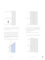
Frameless Flow
Positionierung der vertikalen Wandhalterung 1830
1. Mitte der Frameless Flow-Installation deinieren
2. Mitte von Platte A und Platte C deinieren. Daraus ergibt sich die Mitte der Halterungen.
Beiungleichmäßigen Platten: von der Mitte der Wand 1185 mm (465/8") nach links und rechts
messen. Bei einer ungleichmäßigen Platte: von der Mitte der Wand 592,5 mm (235/16") nach links
und rechts messen.
3. Decke deinieren für die Montage vom Boden.
4. 220 mm (811/16") von der vordeinierten Decke der Wand nach unten messen. Diese Markierung ist
die Unterseite der oberen Wandhalterung
5. 1515 mm (595/8") von der ersten horizontalen Wandhalterung nach unten messen, um die Position
der zweiten Halterung zu deinieren.
6. Die vorgebohrten Löcher der Wandhalterung als Vorlage für die Markierung aller Löcher verwenden.
6,5 mm (1/4") Loch in Trockenwand vorbohren. Alle Anker in die Löcher einsetzen und bündig
festschrauben. Alle Halterung festziehen. Sicherstellen, dass die oberen Halterungen perfekt
ausgerichtet, nivelliert und festgezogen sind. Für alle Halterungen wiederholen.
Vorderansicht
Frameless Flow
Positionierung der vertikalen Wandhalterung 2420
1. Mitte der Frameless Flow-Installation deinieren.
2. Mitte von Platte A und Platte C deinieren. Daraus ergibt sich die Mitte der Halterungen.
Beiungleichmäßigen Platten: von der Mitte der Wand 1185 mm (465/8") nach links und rechts
messen. Bei einer ungleichmäßigen Platte: von der Mitte der Wand 592,5 mm (235/16") nach links
und rechts messen.
3. Decke deinieren, um die Montage vom Boden aus durchzuführen.
4. 220 mm (811/16") von der vordeinierten Decke der Wand nach unten messen. Diese Markierung ist
die Unterseite der oberen Wandhalterung.
5. 1065 mm (4115/16") von der ersten horizontalen Wandhalterung nach unten messen, um die
Position der zweiten Halterung zu deinieren und 2105 mm nach unten zur dritten zu messen.
6. Die vorgebohrten Löcher der Wandhalterung als Vorlage für die Markierung aller Löcher verwenden.
6,5 mm (1/4") großes Loch in Trockenwand vorbohren. Alle Anker in die Löcher einsetzen und
bündig festschrauben. Alle Halterung festziehen. Sicherstellen, dass die oberen Halterungen perfekt
ausgerichtet, nivelliert und festgezogen sind. Für alle Halterungen wiederholen.
Vorderansicht
Doc # 143842 | Rev A | Page 31 of 38 Doc # 143842 | Rev A | Page 30 of 38

Frameless Flow
Positionierung der horizontalen Wandhalterung 1830
1. Mitte der Frameless Flow-Installation deinieren
2. Mitte von Platte A und Platte C deinieren. Daraus ergibt sich die Mitte der Halterungen. Bei
ungleichmäßigen Platten: von der Mitte der Wand 1830 mm (72") nach links und rechts messen. Bei
einer ungleichmäßigen Platte: von der Mitte der Wand 915 mm (36") nach links und rechts messen.
3. Decke deinieren für die Montage vom Boden.
4. 220 mm (811/16") von der vordeinierten Decke der Wand nach unten messen. Diese Markierung ist
die Unterseite der oberen Wandhalterung
5. 870 mm (341/4") von der ersten horizontalen Wandhalterung nach unten messen, um die Position
der zweiten Halterung zu deinieren.
6. Die vorgebohrten Löcher der Wandhalterung als Vorlage für die Markierung aller Löcher verwenden.
6,5 mm (1/4") Loch in Trockenwand vorbohren. Alle Anker in die Löcher einsetzen und bündig
festschrauben. Alle Halterung festziehen. Sicherstellen, dass die oberen Halterungen perfekt
ausgerichtet, nivelliert und festgezogen sind. Für alle Halterungen wiederholen.
Vorderansicht
Frameless Flow
Positionierung der horizontalen Wandhalterung 2420
1. Mitte der Frameless Flow-Installation deinieren.
2. Mitte von Platte A und Platte B/C messen. Daraus ergibt sich die Mitte der Halterungen. Bei
ungleichmäßigen Platten: von der Mitte der Wand 550 mm (215/8") + 1320 mm (5115/16") + 1100 mm
(435/16") nach links und rechts messen. Bei einer ungleichmäßigen Platte: von der Mitte der Wand
660mm (26") + 1100 mm (425/16") nach links und rechts messen.
3. Decke deinieren, um die Montage vom Boden aus durchzuführen.
4. 220 mm (811/16") von der vordeinierten Decke der Wand nach unten messen. Diese Markierung ist die
Unterseite der oberen Wandhalterung
5. 870 mm (341/4") von der ersten horizontalen Wandhalterung nach unten messen, um die Position der
zweiten Halterung zu deinieren.
6. Die vorgebohrten Löcher der Wandhalterung als Vorlage für die Markierung aller Löcher verwenden.
6,5 mm (1/4") großes Loch in Trockenwand vorbohren. Alle Anker in die Löcher einsetzen und bündig
festschrauben. Alle Halterung festziehen. Sicherstellen, dass die oberen Halterungen perfekt ausgerichtet,
nivelliert und festgezogen sind. Für alle Halterungen wiederholen.
Vorderansicht
Doc # 143842 | Rev A | Page 33 of 38 Doc # 143842 | Rev A | Page 32 of 38

7. Platte A auf den Wandhalterungen platzieren, indem sie oberhalb der Halterungen gegen
die Wand gehalten wird und zu den Wandhalterungen hin geschoben wird. Sicherstellen,
dass die Platte perfekt nivelliert ist.
8. Vor dem Einsetzen des vertikalen Proils die Nut reinigen. Das vertikale Proil beginnend
bei 10 mm (3/8") von der Oberseite der Platte in die Nut einsetzen. Die vorgebohrten
Löcher als Vorlage zur Markierung der Löcher verwenden. Das Proil entfernen und
ein Loch von 6,5 mm (1/4") in die Trockenwand bohren. Anker in die Löcher einsetzen
und bündig festschrauben. Das vertikale Proil erneut einführen und am Kontaktpunkt
zwischen Proil und Wand festziehen. Sicherstellen, dass das Proil zumindest oben, in der
Mitte und unten festgezogen ist.
Sicherstellen, dass das vertikale Proil über die Länge der Platte vollständig eingesetzt ist.
9. Positionierung von Platte B/C: Die Unterseite der Platte vorsichtig schräg an der Ecke
der Unterseite einsetzen. Die Platte zur zuvor montierten Platte gleiten lassen, dabei
sicherstellen, dass die Platten über die Länge der Platte Kontakt haben und auf der
horizontalen Wandhalterung einrasten lassen.
Mit jeder Platte B wiederholen.
Nachdem alle Platten B montiert sind, den Schritt für Platte C wiederholen.
Tipp: Zum Entfernen der Platte die Montage in umgekehrter Reihenfolge durchführen.
Doc # 143842 | Rev A | Page 35 of 38 Doc # 143842 | Rev A | Page 34 of 38

polyvision.com 31.07.19-DE
CeramicSteel-Oberfläche: Dauergarantie
Paneelkonstruktion: Beschränkte Garantie über 10 Jahre
Zubehör: Beschränkte Garantie über 2 Jahre
Garantie für gemeinschaftliche Produkte
PolyVision garantiert, dass alle porzellan-emaillierten Oberflächen und/oder Produkte, die mit
e3™ CeramicSteel (Premiumschreiboberflächen) oder a3™ CeramicSteel (gemeinschaftliche
Produkte) hergestellt wurden, ihre Qualität bei Beschreibbarkeit und Reinigung unverändert
beibehalten und dass Glanzvarianz und Farbkonstanz in der Gebäude- oder Produktlebenszeit
erhalten bleiben, je nachdem, welcher Zustand zuerst eintritt.
PolyVision garantiert für einen Zeitraum von 10 Jahren, dass sich die Paneele unter normalen
atmosphärischen Bedingungen und unter Ausschluss von Feuchtigkeit nicht vom Trägermaterial
ablösen und dass sie sich nicht verziehen.
PolyVision garantiert, dass unser Zubehör, einschließlich, jedoch nicht beschränkt auf die
Collaborative ToolBar und runde magnethaftende Tafelwischer, bei Gebrauch unter normalen
Bedingungen für einen Zeitraum von 2 Jahren wie vorgesehen funktionieren wird.
Verbrauchsgüter wie Marker und Kreidestifte fallen nicht unter die Gewähr für Zubehör.
Bei Nichteinhaltung der vorstehenden Garantie korrigiert PolyVision nach schriftlicher
Benachrichtigung durch den Kunden und nach eigener Wahl die Nichteinhaltung durch
Instandsetzung oder Ersatz. Die Korrektur in der oben angegebenen Weise stellt die Erfüllung aller
Verpflichtungen von PolyVision im Hinblick auf die Qualität von CeramicSteel dar. Die Garantie
gilt nur bei normaler Verwendung und Pflege und deckt keine Schäden ab, die durch
unsachgemäße Bedienung, Vandalismus, Missbrauch oder durch Missachtung der
Gebrauchsanleitungen und Pflegeempfehlungen von PolyVision entstanden sind.
Die Garantie erlischt, wenn der Kunde oder andere Parteien die Produkte mit oder ohne
schriftliche Zustimmung bzw. vorherige Kenntnis von PolyVision in irgendeiner Form verändern.
Die Garantie beinhaltet nicht die Kosten von Abbau und Wiederaufbau. Diese Garantie gilt ab dem
12. Juli 2019 und ersetzt alle Oberflächengarantiebedingungen, die PolyVision zuvor gegenüber
dem Kunden erklärt hat.
Diese beschränkte Garantie ist das einzige Mittel bei Produktfehlern. Es wird keine weitere
ausdrückliche oder stillschweigende Garantie gegeben, einschließlich, aber nicht beschränkt
auf, stillschweigende Garantien für die allgemeine Gebrauchstauglichkeit oder die Eignung
für einen bestimmten Zweck. PolyVision übernimmt keine Verantwortung für Folgeschäden
oder Störfälle, die durch Defekte an einem Produkt entstanden sind.
©2019 PolyVision Corporation. Alle Rechte vorbehalten. Die hierin verwendeten Handelsmarken sind Eigentum der
PolyVision Corporation oder ihrer jeweiligen Eigentümer. Die PolyVision Corporation behält sich das Recht vor, ohne
vorherige Ankündigung Veränderungen an der Gestaltung, Konstruktion oder an Einzelheiten der Produkte vorzunehmen
und die Herstellung von Produkten oder Materialien einzustellen.
Doc # 143842 | Rev A | Page 37 of 38 Doc # 143842 | Rev A | Page 36 of 38

©2019 PolyVision Corporation. All rights reserved. Trademarks used herein are the property of PolyVision
Corporation or of their respective owner. PolyVision Corporation reserves the right to make changes
in product design, construction or detail, and to discontinue any product or material without notice.
polyvision.com 28102019
PolyVision Americas
10700 Abbotts Bridge Road
Suite 100
Johns Creek, GA 30097 USA
T 1 888 325 6351
E info@polyvision.com
PolyVision Europe
Zuiderring 56
3600 Genk, Belgium
T +32 89 32 31 30
PolyVision Asia-Pacific
15th Floor, Kinwick Centre
32 Hollywood Road, Central District
Hong Kong
T +852 2520 0160
-
 1
1
-
 2
2
-
 3
3
-
 4
4
-
 5
5
-
 6
6
-
 7
7
-
 8
8
-
 9
9
-
 10
10
-
 11
11
-
 12
12
-
 13
13
-
 14
14
-
 15
15
-
 16
16
-
 17
17
-
 18
18
-
 19
19
-
 20
20