Intertherm M2 Manuel utilisateur
- Catégorie
- Cheminées
- Taper
- Manuel utilisateur
Ce manuel convient également à

User’s Information Manual
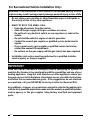
WARNING: If the information in this manual is not followed exactly, a fire or
explosion may result causing property damage, personal injury, or loss of life.
FOR YOUR SAFETY
Advertissement: Quiconque ne respecte pas à la lettre le instructions dans le
présent manuel risque de déclencher un incendie ou une explosion entraînant
des dommages matériels, des lésions corporelles ou la perte de vies humaines.
M2 Series Furnaces
— Ne pas entreposer ni utiliser de l’essence ni d’autres vapeurs ou liquides
inflammables dans le voisinage de cet appareil, ni de tout autre appareil.
— QUE FAIRE S’UL Y A UNE ODEUR DE GAZ
• Ne pas tenter d’allumer aucun appareil.
• Ne toucher à aucun interrupteur électrique; n’utiliser aucun téléphone
dans le bâtiment.
• Appeler immédiatement le fournisseur de gaz en employant le téléphone
d’un voisin. Respecter à la lettre les instructions du fournisseur de gaz.
• Si personne ne répond, appeler le service des incendies.
— L’installation et l’entretien doivent être effectués par un installateur
qualifié, un organisme de service ou le fournisseur de gaz.
— Do not store or use gasoline or other flammable vapors and liquids in the
vicinity of this or any other appliance.
— WHAT TO DO IF YOU SMELL GAS:
• Do not try to light any appliance.
• Do not touch any electrical switch; do not use any phone in your
building.
• Immediately call your gas supplier from a neighbor's phone. Follow the
gas supplier's instructions.
• If you cannot reach your gas supplier, call the fire department.
• Extinguish any open flame.
— Installation and service must be performed by a qualified installer, service
agency, or the gas supplier.
POUR VOTRE SÉCURITÉ

2
IMPORTANT
Read this owner information thoroughly before attempting to operate or
maintain this furnace to become familiar with the capabilities and use of your
heating appliance. Keep this with literature on other appliances where you
have easy access to it in the future. If a problem occurs, check the instructions
and follow the recommendations given. If the suggestions do not eliminate
your problem, call your NORDYNE Servicing Contractor (Service PRO).
Any additions, changes, or conversions required in order for the appliance to
satisfactorily meet the application needs must be made by a qualified installer,
service agency, or the gas supplier using factory specified and approved
parts.
For Recreational Vehicle Installation Only:
WARNING: If the information in this manual is not followed exactly, a fire or
explosion may result causing property damage, personal injury, or loss of life.
– Do not store or use gasoline or other flammable vapors and liquids in
the vicinity of this or any other appliance.
– WHAT TO DO IF YOU SMELL GAS:
Evacuate all persons from the vehicle.
Shut off the gas supply at the gas container or source.
Do not touch any electrical switch, or use any phone or radio in the
vehicle.
Do not start the vehicle's engine or electric generator.
Contact the nearest gas supplier or qualified service technician for
repairs.
If you cannot reach a gas supplier or qualified service technician,
contact the nearest fire department.
Do not turn on the gas supply until the gas leak(s) has been repaired.
– Installation and service must be performed by a qualified installer,
service agency or the gas supplier.

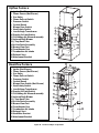
Figure 29. Location of Major Components
Downflow Furnace
Upflow Furnace
1 Ignitor (Not Shown)
2 Flame Sensor (Not Shown)
3 Gas Valve
4 Flame Roll-out Switch
5 Pressure Switch
6 Control Board
7 Blower Door Switch
8 Vent Safety Switch
9 Low Voltage Transformer
10 Supply Air Limit Switch
11 Circulating Air Blower Assembly
12 Induced Draft Blower
13 J Trap Hard Tube
14 In-Line Drain Assembly
15 Burner View Port
16 Front Header Box
17 Combustion Air Intake
18 Exhaust Vent
19 Attachment Bracket
3
4
9
10
11
12
17
19
5
6
7
8
15
16
13
14
21
1
1 Ignitor (Not Shown)
2 Flame Sensor (Not Shown)
3 Gas Valve
4 Flame Roll-out Switch
5 Pressure Switch
6 Control Board
7 Blower Door Switch (Not Shown)
8 Vent Safety Switch
9 Low Voltage Transformer
10 Supply Air Limit Switch
11 Circulating Air Blower Assembly
12 Induced Draft Blower
13 J Trap Hard Tube
14 In-Line Drain Assembly
15 Burner View Port
16 Front Header Box
17 Combustion Air Intake
18 Exhaust Vent
19 VentilAire Bracket
20 Attachment Bracket
3
4
9
10
12
17
19
5
6
8
14
15
16
20
11
1
13

4
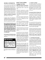
ABOUT YOUR CENTRAL
FURNACE SYSTEM
NORDYNE has been involved in the
design of products for the manufac-
tured home industry since the first
manufactured home or trailer was
built.
NORDYNE originated the sealed
combustion system, which separates
the furnace combustion system from
the living area of the home and is now
a standard for the manufactured home
industry.
NORDYNE engineers developed the
first central heating system and the
first central air conditioner for manu-
factured homes.
NORDYNE is dedicated to bringing
to its customers the finest heating
and cooling comfort possible.
NORDYNE constantly seeks to fur-
ther refine its products to continu-
ously provide exceptional comfort.
Follow the instructions in this booklet
carefully and this appliance will pro-
vide many years of superior perfor-
mance.
If you wish to cool your home auto-
matically with a central air condition-
ing system investigate the excellent
NORDYNE cooling systems available
from your heating and cooling con-
tractor. These systems are designed
to work best with your NORDYNE
furnace and have been carefully en-
gineered to deliver optimal perfor-
mance when mated with NORDYNE
manufactured home furnaces.
NORDYNE also offers water heat-
ers, fireplaces and ventilating sys-
tems specifically designed for manu-
factured housing applications. Ask
your manufactured home retailer, your
heating and cooling contractor, or your
distributor for more information. Write
directly to the factory (PO Box 46911,
St. Louis, MO 63146) if you are un-
able to locate a source for NORDYNE
manufactured housing products in
your area.
1. Furnace Location
The furnace area and the vicinity of
any other gas appliance must be kept
clear and free of combustible materials,
gasoline, and other flammable vapors
and liquids. Do not store or use
flammable items such as paint,
varnish, or strippers in the vicinity of
the furnace.
Do not use the furnace closet or area
next to the furnace as a storage area.
This area must be kept clear, clean,
and free of lint. The furnace must also
be kept clear of loose or exposed
insulation materials. Examine the
furnace area when the furnace is
installed or when insulation is added.
Some insulation materials may be
combustible.
Do not use this furnace if any part has
been under water. Immediately call a
qualified service technician to inspect
the furnace and to replace any part of
the control system and any gas control
which has been under water.
Familiarize yourself with the controls
that shut off the gas and electrical
power to the furnace. If the furnace is
to be shut down for an extended period
of time, turn off both the gas and
electrical power. For your safety
always turn off both the gas and
electrical power before performing
service or maintenance on the furnace.
2. Combustion Air Supply
A furnace needs an adequate supply
of combustion and ventilation air for
proper and safe operation. Follow the
installation instructions included with
the furnace to properly vent air to the
combustion air inlet and exhaust the
products of combustion to the outside
from the exhaust vent.
If the furnace is operated with a
restricted combustion air supply, the
pressure switch will open, turning off
the gas supply to the burners. (See
Figure 1). DO NOT install a jumper
wire across this switch to defeat its
function. If this switch must be
replaced, use only authorized
replacement parts from your
authorized distributor.
GENERAL INFORMATION
This furnace has been designed and
built to provide many years of safe
and dependable home comfort, pro-
viding it is properly installed and main-
tained. With regular maintenance, this
furnace will operate satisfactorily year
after year. Abuse, improper use, and/
or improper maintenance can shorten
the life of the furnace and create haz-
ards for you. Please read this manual
carefully to familiarize yourself with
operation, maintenance, and safety
procedures for this furnace.
A regular service and maintenance
schedule should be established to
insure efficient and safe operation of
the furnace. See Section 5 for main-
tenance procedures and schedules.
Devices attached to the flue or vent
for the purpose of reducing heat
loss up the chimney have not been
tested and have not been included
in the design certification of this
furnace. We, the manufacturer, can
not and will not be responsible for
injury or damage caused by the
use of such untested and/or
uncertified devices, accessories,
or components.
Be sure that the thermostat is prop-
erly installed and is not being affected
by drafts or heat from lamps or other
appliances.
To avoid possible equipment
damage, fire, or death, the
following instructions must be
observed regarding furnace
location, combustion air
requirements, and operation
procedures.
!
WARNING:
Inspect the furnace installation to en-
sure that the vent and combustion air
intake pipes have been installed prop-
erly.

5
If the furnace is operated with
inadequate combustion air supply, the
flame roll-out control switch located
above the burners may open, turning
off the gas supply to the burners. The
flame roll-out control is a manually
resettable device (See Figure 1). DO
NOT install a jumper wire across this
switch to defeat its function. DO NOT
reset the control without identifying
and correcting the fault condition which
caused the control to trip. If this switch
must be replaced, use only authorized
replacement parts from your
authorized distributor.
Air openings in warm air registers,
and return air grilles must not be
restricted.
To maximize heat exchanger life, the
combustion air must be free of
chemicals which form corrosive acidic
compounds in the combustion gases.
Some examples of these chemicals
are chlorine, fluorine, and sulphur.
Some common sources of these
chemicals are detergents, bleaches,
aerosol sprays, cleaning solvents, and
a wide variety of commercial and
household products.
3. Return Air Supply
For upflow models, the return air
opening is located in the bottom of the
furnace. For downflow models, the
return air opening is located at the top
of the furnace. The floor or platform
on which the furnace is mounted must
provide sound physical support of the
furnace with no gaps, cracks, or
sagging between the furnace and floor
or platform. The circulating air
ductwork must not be connected to
any other heat producing device such
as a fireplace insert, stove, etc. Doing
so may result in fire, explosion,
personal injury, carbon monoxide
poisoning, or property damage.
Use an air filter in the return air duct to
maintain a clean heat exchanger.
4. Vent System
The furnace must always be
connected to an approved vent pipe
to carry the furnace combustion
products outdoors. At the beginning
and end of each heating season,
inspect the outdoor vent terminal
closely with a flashlight to determine if
any of the conditions listed under the
following warning exist.
• Do not place combustible
materials on or against the
furnace cabinet.
• Do not store gasoline or any
other flammable vapors and
liquids in the vicinity of the
furnace.
• Annually inspect the furnace,
ductwork, and vent system for
signs of physical deterioration.
• Change or replace the air filters
monthly during any period
when the circulating blower is
operating regularly.
• Always replace the doors on
the furnace after servicing or
cleaning/changing the filters.
Do not operate the furnace
without all doors and covers in
place, except to check burner
operation.
• Avoid operating the furnace
when windows and doors are
open.
• Be sure that the thermostat is
Combustion air must not be
drawn from a corrosive
atmosphere.
CAUTION:
!
Failure to prevent products
of combustion from being
circulated into the living
space can create potentially
hazardous conditions
including carbon monoxide
poisoning that could result
in personal injury or death.
WARNING:
!
Never operate the furnace
without a filter in place. Dust
and lint in the return air can
build up on the internal
components, resulting in a
loss of efficiency, equipment
damage, and possible fire.
WARNING:
!
5. Maintenance
Proper maintenance is most important
to achieve the best performance from
this furnace and should be performed
by a qualified service technician.
Follow the maintenance schedule (see
Table 1) and the following instructions
for years of safe, trouble free operation.
WARNING:
Do not operate your furnace if
you find any of the following
conditions. Such conditions
may allow toxic fumes to
escape into your home:
• Obstructions or
restrictions in the vent pipe
and/or chimney.
• Holes or cracks in the vent
pipe.
• Visible corrosion in the vent
pipe.
• Horizontal vent pipes that
do not slope upward.
If any of the above conditions
are found in the vent pipe, call
a qualified service technician
to install new vent pipe.
!
properly installed and is not
being affected by drafts or heat
from lamps or other appliances.
Air Filter(s) — An air filter is supplied
with the furnace as shipped from the
factory. The filter must be removed
and cleaned monthly during the
heating season to ensure proper
furnace operation. New or newly
renovated homes may require more
frequent changing until the
construction dust has been removed.
Always replace the filter with a filter of
the same size and type as the filter
being removed.

6
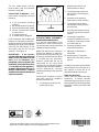
the burner through the view hole to
make sure that the flame is drawn into
the center of the heat exchanger tube
(See Figure 2). In a properly adjusted
burner assembly, the flame bends
down and to the right at the end of the
heat exchanger tube, and the end of
the flame will be out of sight around
the bend. The flame color should be
blue, however some light yellow
streaks may occur on the outer
portions of the flame.
Always replace the door(s) on the
furnace after servicing or cleaning/
changing the filters. Do not operate the
furnace without the door(s) in place.
Lubrication — The bearings in the
circulating air blower motors used in
these furnaces are pre-lubricated and
sealed at the factory. No further oiling
of the bearings is required for the life
of the motor.
Blower Compartment — The blower
compartment should be cleaned
monthly during the heating and cooling
seasons to remove any dirt and lint
that may have accumulated in the
compartment or on the blower and
motor. Buildup of dirt and lint on the
blower and motor can create
excessive loads on the motor resulting
in higher than normal operating
temperatures and possible shortened
service life.
Burner Maintenance — Check the
burner flames at the start of every
heating season. Set the thermostat to
a temperature setting above the room
temperature. Remove the top door
from the furnace and visually inspect
6. Operating Instructions
READ THE SAFETY INFORMA-
TION ON PAGE 7 BEFORE
OPERATING.
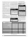
Table 1. Maintenance Table
Some components in the
burner vestibule are at high
temperatures while the
burners are operating. Use
caution to avoid personal
injury.
CAUTION:
!
Do not strike any of the internal
electrical components while
vacuuming.
CAUTION:
!
MAINTENANCE ITEM BEGINNING OF END OF EACH
EACH HEATING SEASON HEATING SEASON MONTHLY
VERIFY FURNACE AREA IS FREE
OF COMBUSTIBLE MATERIALS
XXX
VERIFY COMBUSTION AND VENTILATION
AIR IS NOT RESTRICTED
XXX
VERIFY NO SIGNS OF PHYSICAL
DETERIORATION OF THE FURNACE
XXX
VERIFY NO OBSTRUCTIONS OR
RESTRICTIONS IN VENT OR CHIMNEY
XX
VERIFY NO HOLES OR CRACKS IN VENT PIPE
XX
VERIFY NO CORROSION IN VENT PIPE
XX
VERIFY THAT HORIZONTAL VENT PIPES
SLOPE UPWARDS AWAY FROM FURNACE
XX
VERIFY BURNER FLAME
X
CLEAN OR REPLACE FILTER(S)
X
CLEAN BLOWER COMPARTMENT
X
CLEAN BURNER ASSEMBLY
X
FREQUENCY OF MAINTENANCE
Should overheating occur, or
the gas supply fail to shut off,
shut off the manual gas valve
to the furnace before shutting
off the electrical supply.
WARNING:
!
En cas de température
excessive, ou s’il est impossible
de couper l’alimentation en gaz,
fermer le robinet manuel
d’alimentation en gaz du
générateur d’air chaud avant de
couper l’alimentation électrique.
ADVERTISSEMENT:
!
These furnaces are equipped with
roll-out limit switch(s), a vent safety
switch, and a pressure switch (See
Figure 1). The pressure switch verifies
that the flame is receiving combustion
air. If the flame is not drawn into the
heat exchanger tube, the roll out limit
switch or flame sensor, will shut the
furnace down.
Inspect the burners, mounting
brackets, and all other parts in the
vestibule for signs of deterioration.
The burner vestibule should be
vacuumed clean and inspected
annually.

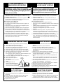
WARNING: If you do not follow these
instructions exactly, a fire or explosion may
result causing property damage, personal
injury, or loss of life.
1. STOP! Read the safety information above on this label.
2. Set the thermostat to the lowest setting.
3. Turn off all electrical power to the appliance.
4. The appliance’s ignition device automatically lights the
burner. Do not try to light burner by hand.
5. Remove the furnace door (upper door if two-door model).
6. Push lever in slightly and move left to OFF. (See Figure 1)
7. Wait five (5) minutes to clear out any gas. Then smell for
gas, including near the base of the unit.
If you smell gas, STOP! Follow “B” in above information. If you
don’t smell gas, go to the next step.
8. Push lever in slightly and move left to “ON”. (See Figure 1 )
9. Replace the furnace door.
1.ATTENTION! Lire d'abord la liste des mesures de sécurité ci-
dessus.
2.Mettre le thermostat à la position minimale.
3.Couper le courant électrique qui mène à l’appareil.
4.Cet appareil ménager étant doté d’un système d’allumage
automatique, ne pas essayer d'allumer le brûleur
manuellement.
5.Retirer la porte à volets d’aération de la chaudière.
6.Pousser légèrement le levier et le déplacer vers la gauche pour
l’amener sur OFF (ARRÊT). (Voir la Figure)
7.Attendre cinq (5) minutes pour s’assurer de la dissipation du
gaz.
En cas d’odeur, ARRÊTER LE PROCÉDÉ. Suivre les instruc-
tions ci-dessus (Section B). En l’absence de toute odeur de
gaz, avancer à l’étape suivante.
8.Pousser légèrement le levier et le déplacer vers la droite pour
l’amener sur ON (MARCHE). (Voir la Figure)
9.Remettre en place la porte à volets d’aération de la chaudière.
1. Set the thermostat to the lowest setting.
2. Turn off all electrical power to the appliance if service is to be
performed.
3. Remove the furnace door (upper door if two-door model).
4. Push gas valve lever in slightly and move left to OFF.
Do not use force. (See Figure 1)
5. Replace the furnace door.
MODE D'EMPLOI
DIRECTIVES D’ARRÊT
1. Mettre le thermostat à la position minimale.
2. Débrancher l’appareil en prévision de la réparation.
3. Retirer la porte à volets d’aération de la chaudière.
4. Pousser légèrement le levier et le déplacer vers la gauche pour
l’amener sur OFF (ARRÊT). Ne pas forcer. (Voir la Figure)
5. Remettre en place la porte à volets d’aération de la chaudière.
A. This appliance does not have a pilot. It is equipped with an
ignition device which automatically lights the burner. Do
not try
to light the burner by hand.
B. BEFORE OPERATING smell all around the appliance area for
gas. Be sure to smell next to the floor because some gas is
heavier than air and will settle on the floor.
WHAT TO DO IF YOU SMELL GAS
• Do not try to light any appliance.
• Do not touch any electrical switch; do not use any phone in
your building.
• Immediately call your gas supplier from a neighbor’s phone.
Follow the gas supplier’s instructions.
• If you can’t reach your gas supplier, call the fire department.
C. Use only your hand to push in or turn the gas control lever.
Never use tools. If the lever will not push in or move by hand,
do not try to repair it, call a qualified service technician. Force
or attempted repair may result in a fire or explosion.
D. Don’t use this appliance if any part has been under water.
Immediately call a service technician to inspect the appliance
and to replace any part of the control system and any gas
control which has been under water.
OPERATING INSTRUCTIONS
A. Cet appareil ménager n'a pas de veilleuse. II est doté d’un
système d’allumage automatique. Ne pas essayer d'allumer le
brûleur manuellement.
B. AVANT L’USAGE. Attention à une possible odeur de gaz
surtout au niveau du plancher où les gaz les plus lourds ont la
tendance de se concentrer.
EN CAS D’ODEUR DE GAZ.
• Ne mettre en marche aucun appareil électrique.
• Ne toucher à aucun commutateur électrique, ne pas employer le
téléphone.
• Quitter le bâtiment immédiatement et avertir la compagnie du
gaz en utili sant le téléphone d'un voisin.
• A défaut de la compagnie du gaz, avertir le service des
pompiers.
C. Tourner le robinet à gaz levier. Ne jamais employer
d’outils. En levier de difficulté, ne pas essayer de le réparer
vous-même. Appeler un spécialiste. Forcer ou tenter de réparer
le robinet peut entraîner une explosion ou un incendie.
D. II est déconseillé d’utiliser cet appareil en contact prolongé avec
l’eau. Faire inspecter ou remplacer toute commande par un
technicien qualifié si un des systèmes de contrôle du gaz s'est
trouvé sous l'eau.
ATTENTION! L’inobservation de ces
instructions peut entraîner un incendie ou une
explosion pouvant causer des dammages à
votre propriété à votre personne, ou la mort.
POUR VOTRE SÉCURITÉ.
À LIRE AVANT L’EMPLOI
FOR YOUR SAFETY
READ BEFORE OPERATING
TO TURN OFF
GAS TO APPLIANCE
LEVER
(LEVIER)
Figure 1
10. Rebrancher l’appareil sur le réseau électrique.
11. Ajuster le thermostat à la position désirée.
12. Si l’appareil ne fonctionne pas, suivre les “Directives d’arrêt”
cidessous et appeler le technicien de service.
10. Turn on all electrical power to
the appliance.
11. Turn the thermostat to a desired
setting.
12. If the appliance will not
operate, follow the instructions
“To Turn Off Gas To Appliance”
and call your service technician.

MANUFACTURER WARRANTY,
OWNER RESPONSIBILITIES
It is the sole responsibility of the
homeowner to make certain the gas
furnace has been correctly set up and
adjusted to operate properly.
NORDYNE warrants this furnace to
be free from defects in material or
workmanship for a period of one year.
A warranty certificate with full details
is included with this document.
However, NORDYNE will not be
responsible for any costs found
necessary to correct problems due to
improper setup, improper installation,
furnace adjustments, improper
operating procedure on the part of the
user, etc.
Some specific examples of service
calls which cannot be included in
warranty payments are:
1. Converting the furnace to use
another type of gas.
2. Repairing duct work in the
home found to be faulty.
3. Correcting wiring problems in
the electrical circuit supplying
the furnace.
4. Resetting circuit breakers,
blown fuses or other switches.
5. Correcting problems due to
improper gas supply pressure
to the furnace.
6. Providing instructional training
on how to light and operate the
furnace.
7. Correcting any problems
caused by installation of an air
conditioner, heat pump or other
air comfort devices.
8. Revising installation of the
furnace flue assembly.
9. Adjusting or calibrating of
thermostat.
10. Removing any construction
debris which has fallen into flue
system.
Carefully review these responsibilities
with your dealer, service company, or
gas supplier so there will be no
misunderstanding at a later time.
Read Your Warranty
Please read your limited warranty
completely. It contains valuable
information about your furnace. If you
have any questions about the warranty
information, contact your NORDYNE
distributor.
The vent safety switch shuts the
furnace down if the vent becomes
blocked or restricted.
Furnace Fails To Operate — If the
furnace does not operate, check the
following:
1) Is the thermostat operating
properly?
2) Are the blower door(s) in place?
3) Is the furnace disconnect closed?
4) Has the circuit breaker tripped
(or fuse blown)?
5) Is the gas turned on?
6) Is the filter dirty or plugged?
If the combustion and circulating air
blowers are operating, and items 1
through 6 have been checked without
identifying the cause of the problem,
press the red reset buttons on the
vent safety and the roll out limit
switches. (See Figure 1).
IMPORTANT: If the furnace
operates after depressing the reset
button on the vent limit or roll out
limit, it is an indication of a
potentially serious problem in the
installation. Follow the instructions
"To Turn Off Gas To the Appliance"
located in these instructions or on
the door of the furnace. Contact a
qualified serviceman to identify and
repair the problem.
Figure 2. Burner Inspection
Burner
Flame
Manifold
¢7078110%¤
7078110
Specifications & illustrations subject to change without notice or incurring obligations (05/15).
O’Fallon, MO, © Nortek Global HVAC LLC 2015. All Rights Reserved.
-
 1
1
-
 2
2
-
 3
3
-
 4
4
-
 5
5
-
 6
6
-
 7
7
-
 8
8


Intertherm M2 Manuel utilisateur
- Catégorie
- Cheminées
- Taper
- Manuel utilisateur
- Ce manuel convient également à
dans d''autres langues
- English: Intertherm M2 User manual
Documents connexes
Autres documents
-
Kelvinator FG6T(C,L) Manuel utilisateur
-
Nordyne M2RL-080A Le manuel du propriétaire
-
Nordyne PGF1TA Manuel utilisateur
-
-
Unbranded R6GD 3 - 5 Ton, 3 Phase Guide d'installation
-
Mammoth R8GE, Single Phase Guide d'installation
-
-
Thermo CLQS1 Le manuel du propriétaire
-
Dometic DF Series Furnace Guide d'installation