Hitachi P-G23WA2 Guide d'installation
- Catégorie
- Climatiseurs split-system
- Taper
- Guide d'installation

RCI UNIT
ENGLISH
ESPAÑOL
DEUTSCH
FRANÇAIS
ITALIANO
PORTUGUÊS
DANSK
NEDERLANDS
SVENSKA
EËËHNIKA
Read and understand this manual before using this air conditioner. Keep this manual for future reference.
Lea cuidadosamente este manual antes de poner en marcha el equipo de aire acondicionado. Guarde este manual en un lugar seguro por si
necesita consultarlo en el futuro.
Diese Bedienungsanleitung vor der inbetriebnahme der Klimaanlage gelesen und verstanden werden. Das Handbuch für spätere
Rückfragen aufbewahren.
Lire attentivement ce manuel avant taute utilization du climatiseur, et le conserver pour référence ultérieure.
Leggere attentamente il presente manuale prima di utilizzare questo condizionatore d’aria. Conservarlo da parte per future consultazioni.
Leia e compreenda este manual antes de operar este ar condicionado. Guarde este manual para futura referencia.
De bor laese og forsta denne vejledning, for de tager dette dlimaanlaeg i brug. Opbervar vejledningen til senere reference.
Lees deze hadleiding aandachtig door alvorens de airconditioning in gebruik te nemen.
Läs och första denna manual innan Du sätter igang luftkonditioneraren. Förvara denna manual förvara denna manual för framtida behow.
mu
ÄéáâÜóôå ðñïóåêôéêÜ áõôü ôï åã÷åéñßäéï ðñéí ôç ÷ñÞ óç ôïõ êëéìáôéóôéêïý. ÊñáôÞóôå ôï åã÷åéñßäéï ãéá ìåëëïíôéêÞ áíáöïñÜ.
ß
INSTALLATION MANUAL
MANUAL DE INSTALACIÓN
INSTALLATIONSANLEITUNG
MANUEL D’INSTALLATION
MANUALE DI INSTALLAZIONE
RCI-1.0FSN1E
RCI-1.5FSN1E
RCI-2.0FSN1E
RCI-2.5FSN1E
RCI-3.0FSN1E
RCI-3.5FSN1E
RCI-4.0FSN1E
RCI-5.0FSN1E
RCI-6.0FSN1E
MANUAL DE MONTAGEM
INSTALLATIONSVEJLEDNING
INSTALLATIEHANDLEIDING
AIRCONDITIONING
INSTALLATIEHANDLEIDING
ERXEIPIAIO ERKAAETAEHE
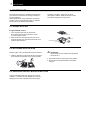
4-WAY CASSETTE TYPE INDOOR UNIT + OPTIONAL AIR PANEL
P-G23WA2


Õ
DANGER – Immediate hazard which WILL result in severe injury or death.
PELIGRO – Riesgos inmediatos que PRODUCIRÁN lesiones personales graves e incluso la muerte.
GEFAHR – Unmittelbare Gefahrenquellen, die zu schweren Verletzungen oder zum Tod führen.
DANGER – Dangers instantanés de blessures corporelles sévères ou de mort.
PERICOLO – Pericolo immediato che PRODURRÀ ferite gravi o la morte.
PERIGO – Problemas imediatos que IRÃO resultar em graves ferimentos pessoais ou morte.
FARE – Overhængende fare, som VIL resultere i alvorlig personskade eller dødsfald.
GEVAAR – Onmiddellijke risico's die ernstige persoonlijke verwondingen of de dood ten gevolge kunnen hebben.
FARA – Omedelbar risk som medför svår personskada eller död.
KINAYNO – Άµεσος κίνδυνος που ΘΑ έχει ως αποτέλεσµα σοβαρές σωµατικές βλάβες ή θάνατο.
Ô
WARNING – Hazards or unsafe practices which COULD result in severe personal injuries or death.
AVISO – Riesgos o prácticas poco seguras que PODRÍAN producir lesiones personales e incluso la muerte.
WARNUNG – Gefährliche oder unsichere Anwendung, die zu schweren Körperverletzungen oder zum Tod
führen kann.
ATTENTION – Utilisation dangereuse ou sans garantie de sécurité qui PEUT provoquer de sévères blessures
personnelles ou la mort.
AVVISO – Pericoli o azioni pericolose che POTREBBERO avere come esito lesioni fisiche gravi o il decesso.
AVISO – Riesgos o prácticas poco seguras que PUEDEN producir lesiones personales e incluso la muerte
ADVARSEL – Farer eller farlig brug, som KAN resultere i alvorlig personskade eller dødsfald.
WAARSCHUWING – Gevaren of onveilige praktijken die ernstig persoonlijk letsel of de dood tot
gevolg KUNNEN hebben.
VARNING – Risker eller osäkra tillvägagångssätt som KAN leda till svåra personskador eller dödsfall.
ΠΡΟΕΙ∆ΟΠΟΙΗΣΗ – Κίνδυνοι ή επικίνδυνες πρακτικές, οι οποίες ΜΠΟΡΕΙ να έχουν ως αποτέλεσµα σοβαρές
σωµατικές βλάβες ή θάνατο.
CAUTION – Hazards or unsafe practices which COULD result in minor personal injury or product or property damage.
PRECAUCIÓN – Riesgos o prácticas poco seguras que PODRÍAN provocar lesiones personales de menor
importancia o daños en el producto u otros bienes.
VORSICHT – Gefährliche oder unsichere Anwendung, die geringfügigen Personen-, Produkt- oder Sachschaden
verursachen kann.
PRECAUTION – Utilisation dangereuse ou sans garantie de sécurité qui PEUT provoquer des blessures mineures
ou des dommages au produit ou aux biens.
ATTENZIONE – Pericoli o azioni pericolose che POTREBBERO avere come esito lesioni fisiche minori o danni
al prodotto o ad altri beni.
CUIDADO – Perigos e procedimentos perigosos que PODERÃO PROVOCAR danos pessoais ligeiros ou danos
em produtos e bens.
FORSIGTIG – Farer eller farlig brug, som KAN resultere i mindre skade på personer, produkt eller ejendom.
LET OP – Gevaren of onveilige praktijken die licht persoonlijk letsel of beschadiging van het product
of eigendommen tot gevolg KUNNEN hebben.
VARSAMHET – Risker eller farliga tillvägagångssätt som KAN leda till mindre personskador eller skador
på produkten eller på egendom.
ΠΡΟΣΟΧΗ – Κίνδυνοι ή επικίνδυνες πρακτικές, οι οποίες ΜΠΟΡΕΙ να έχουν ως αποτέλεσµα την πρόκληση
ελαφρών σωµατικών βλαβών ή καταστροφή περιουσίας.

IMPORTANT NOTE:
The FSN1E units refered in this manual can be operated with R407C or R410A depending on
Outdoor Unit Combination. Refer to the system information located in the manual of the
Outdoor Unit.
NOTA IMPORTANTE:
The FSN1E units refered in this manual can be operated with R407C or R410A depending on
Outdoor Unit Combination. Refer to the system information located in the manual of the
Outdoor Unit.
WICHTIGER HINWEIS:
The FSN1E units refered in this manual can be operated with R407C or R410A depending on
Outdoor Unit Combination. Refer to the system information located in the manual of the
Outdoor Unit.
NOTE IMPORTANTE :
The FSN1E units refered in this manual can be operated with R407C or R410A depending on
Outdoor Unit Combination. Refer to the system information located in the manual of the
Outdoor Unit.
NOTA IMPORTANTE:
The FSN1E units refered in this manual can be operated with R407C or R410A depending on
Outdoor Unit Combination. Refer to the system information located in the manual of the
Outdoor Unit.
NOTA IMPORTANTE:
The FSN1E units refered in this manual can be operated with R407C or R410A depending on
Outdoor Unit Combination. Refer to the system information located in the manual of the
Outdoor Unit.
VIGTIG INFORMATION:
The FSN1E units refered in this manual can be operated with R407C or R410A depending on
Outdoor Unit Combination. Refer to the system information located in the manual of the
Outdoor Unit.
BELANGRIJKE OPMERKING:
The FSN1E units refered in this manual can be operated with R407C or R410A depending on
Outdoor Unit Combination. Refer to the system information located in the manual of the
Outdoor Unit.
VIKTIGT!
The FSN1E units refered in this manual can be operated with R407C or R410A depending on
Outdoor Unit Combination. Refer to the system information located in the manual of the
Outdoor Unit.
ΣΗΜΑΝΤΙΚΗ ΣΗΜΕΙΩΣΗ: The FSN1E units refered in this manual can be operated with R407C or R410A depending on
Outdoor Unit Combination. Refer to the system information located in the manual of the
Outdoor Unit.

1
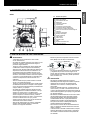
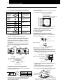
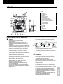
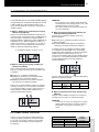
NAME OF PARTS
1
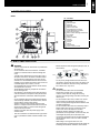
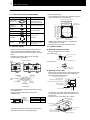
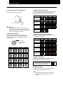
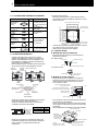
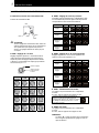
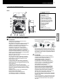
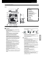
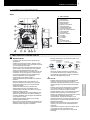
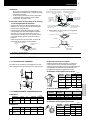
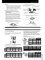
1. NAME OF PARTS
RCI
No. Part Name
1 Fan
2 Fan Motor
3 Heat Exchanger
4 Distributor
5 Expansion Valve
6 Electric Control Box
7 Gas Refrigerant Connection
8 Liquid Refrigerant Connection
9 Drain Pipe Connection
10 Motor for Drain Discharge Mechanism
11 Float Switch
12 Drain Pan
13 Panel P-G23WA2
14 Air Filter
15 Air Outlet
16 Air Inlet
17 Strainer
18 Air Inlet Grille
19 Cover for Corner Pocket
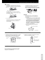
2. UNITS INSTALLATION
Ô WARNING:
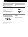
- Check to ensure that the accessories are packed with
the indoor unit.
- Do not install the indoor units outdoors. If installed
outdoors, an electric hazard or electric leakage will
occur.
- Consider the air distribution from each indoor unit to
the space of the room, and select a suitable location
so that uniform air temperature in the room can be
obtained. It is recommended that the indoor units be
installed 2.3 to 3 meters from the floor level. If the unit
is installed higher than 3 meters, it is also
recommended that a fan be utilised to obtain uniform
air temperature in the room.
- Avoid obstacles which may hamper the air intake or
the air discharge flow.
- Pay attention to the following points when the indoor
units are installed in a hospital or other places where
there are electronic waves from medical equipment,
etc.
- Do not install the indoor units where electromagnetic
wave is directly radiated to the electrical box, remote
control cable or remote control switch.
- Prepare a steel box and install the remote control
switch in it. Prepare a steel conduit tube and wire the
remote control cable in it. Then connect the ground
wire with the box and tube.
- Install a noise filter when the power supply emits
harmful noises..
- This unit is exclusive non electrical heater type indoor
unit. It is prohibited to install a electrical heater in the
field.
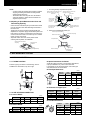
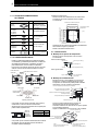
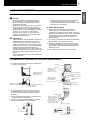
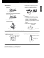
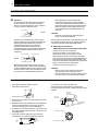
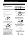
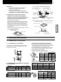
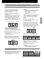
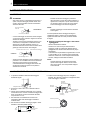
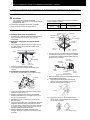
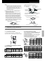
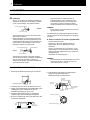
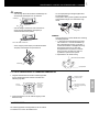
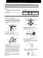
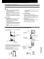
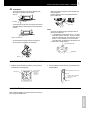
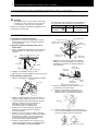
- Mount suspension bolts using M10 (W3/8) as size, as
shown below:
- Do not put any foreign material into the indoor unit
and check to ensure that none exist in the indoor unit
before the installation and test running. Otherwise a
fire or failure, etc., may occur.
CAUTION:
- Do not install the indoor units in a flammable
environment to avoid a fire or an explosion.
- Check to ensure that the ceiling slab is strong
enough. If not strong enough, the indoor unit may fall
down on you.
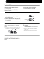
- Do not install the indoor units, outdoor unit, remote
control switch and cable within approximately 3
meters of strong electromagnetic wave radiators such
as medical equipment.
- Do not install the indoor units in a machinery shop or
kitchen where vapor from oil or mist flows to the
indoor units. The oil will deposit on the heat
exchanger, thereby reducing the indoor unit
performance, and may deform. In the worst case, the
oil damages the plastic parts of the indoor unit.
- To avoid any corrosive action to the heat exchangers,
do not install the indoor units in an acid or alkaline
environment.
- When lifting or moving the indoor unit, use
appropriate slings to avoid damage and be careful not
to damage the insulation material on units surface.
Square
washers
Wooden Bar
(60 mm to 90 mm Square)
Wooden Beam
Sling Bolt
(W3/8 or M10)
For Concrete Slab
150~160mm
Concrete
A
nchor Bolt
Steel
I-Beam
Suspension Bolts
(W3/8 or M10)
Nuts

2
2
UNITS INSTALLATION
2.1. UNIT INSTALLATION
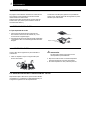
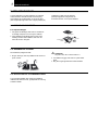
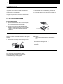
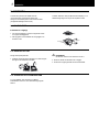
2.1.1. FACTORY-SUPPLIED ACCESSORIES
Accessory Qty. Purpose
Paper Pattern
(Carton Board)
1
For Adjusting Space of
False Ceiling Opening
and Position of the Unit
Cross
Recessed
Head Screws
4 For Fitting Paper Pattern
Washer with
Insulation
4
Washer (M10)
4
For Unit Installation
Drain Hose
1
Wire Clamp
2
For Drain Hose
Connection
Reducer 1
For
RCI-(4.0/5.0/6.0)FSN1E
(R410A only)
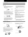
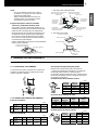
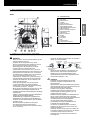
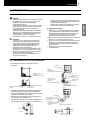
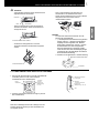
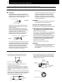
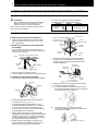
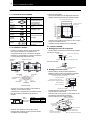
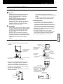
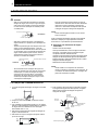
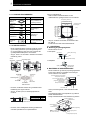
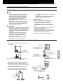
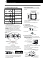
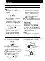
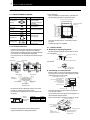
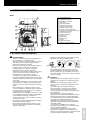
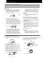
2.1.2. INITIAL CHECK
- Install the indoor unit with a proper clearance around it
paying careful attention of installation direction for the
piping, wiring and maintenance working space, as shown
below.
- Provide a service access door near the unit piping
connection area on the ceiling.
Service Space
-
Check space between ceiling and false ceiling is enough
as indicated below.
- Check the ceiling surface is flat for the air panel
installation work.
Unit HP A(mm)
RCI-1.0 to 2.5HP 248
RCI-3.0 to 6.0HP 298
- Check down slope Pitch of Drain Piping is following the
specifications indicated in chapter Drain Piping.
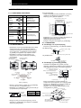
Opening Of False Ceiling
- Cut out the area for the indoor unit in the false ceiling and
install suspension bolts, as shown below:
- Check to ensure that the ceiling is horizontally level,
otherwise water can not flow.
- Strengthen the opening parts of the false ceiling.
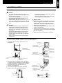
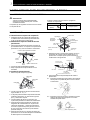
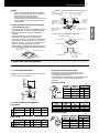
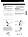
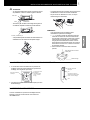
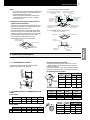
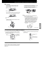
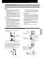
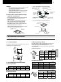
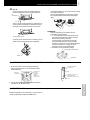
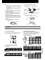
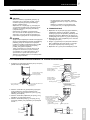
2.1.3. INSTALLATION
Mounting of Suspension Bolts
- Mount the suspension bolts, as shown.
For concrete slab:
For steel beam:
Mounting of Indoor Unit
- Mount the nuts and the washers to the suspension bolts.
Put the washer so that the surface with insulation can
faces downwards as shown below:
- Consider piping connection side before lift indoor unit
- Lift the indoor unit by hoist, and do not put any force on
the drain pain
- Secure the indoor unit using the nuts, washers.
Piping
Connection
Service
A
ccess Doo
r
Service Access Door
Clearance:
10-20mm
Unit High
In False Ceiling
Gas piping connection
Suspension bolts (4)
False ceiling
Drain piping connection
Liquid piping
Panel
(to be installed later,
shown only as a reference)
Wiring hole (30x30)
Open the knockout hole for
wiring (Ø32,5)
Suspension Bracket
Dimension of Suspension
Bolts: 760
4-Positions of
Suspension Bolts
Dimension of Opening: 860 to 910
Piping Connection
Side
Drain Piping
Connection Side
Optional Panel
150 to 160mm Insert (100 to 150Kg)
I Concrete
A
nchor Bolt (W3/8 or M10)
Steel
I-Beam
Suspension Bolt
(w3/8 or M10)
Unit size: 840
Dimension of Opening: 860 to 910
Unit size: 840
Dimension of Suspension
Bolts: 760
(mm)
Suspension Bolts (Field-Supplied)
Nut (Field-Supplied)
Washer with Insulation (Accessory)
Washer (Accessory)
Nut (Field-Supplied)
Suspension Bracket (Attached Indoor Unit)
Surface of Ceiling
102
Aprox. 52
(mm)
Aprox. 50
500 mm Min.
500 mm Min.
100 mm Min.
100 mm Min.
1000 mm Min.
Piping Connection
Side

3
REFRIGERANT PIPING
3
NOTE:
- If a false ceiling has already been installed, complete
all piping and wiring work inside the ceiling before
hooking-up the indoor unit.
- Secure the indoor unit using the nuts, flat washers
and spring washers. (These nuts and washers are
supplied, 4 pieces each).
Adjusting of Space Between Indoor Units and
False Ceiling Opening
- Check the level of the drain pan by a water level to avoid
incorrect operation of the drain discharge mechanism in
the indoor unit.
- Tighten the nuts of the suspension brackets after the
adjustment is completed. Apply LOCK-TIGHT paint to the
bolts and nuts in order to prevent them from loosening. If
not done, abnormal noises or sounds may occur and the
indoor unit may come loose.
- Adjust the indoor unit to the correct position while
checking with the pattern for installation.
1. For ceiling already completed with panels.
2. Ceiling not completed with panels yet.
3. REFRIGERANT PIPING
3.1. PIPING CONNECTION
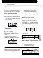
3.1.1. PIPING POSITION
Position of piping connection is the following, which is
available from all directions, top, left or right.
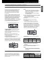
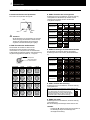
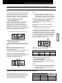
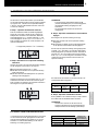
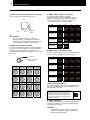
3.1.2. SIZE OF PIPING CONNECTION
In case of R407C
(mm)
Model RCI 1.0/1.5 2.0 2.5/3.0/3.5 4.0/5.0/6.0
o
Gas Piping 12.7 15.88 15.88 19.05
p
Liquid Piping 6.35 6.35 9.53 9.53
In case of R410A
(mm)
Model RCI 1.0/1.5 2.0 2.5/3.0/3.5 4.0/5.0/6.0
o
Gas Piping 12.7 15.88 15.88 15.88
p
Liquid Piping 6.35 6.35 9.53 9.53
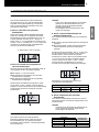
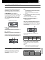
Special instructions for R410A
As R410A pressure is about 1.4 times higher than R407C,
improper installation may cause a serious trouble.
It is necessary to use the copper pipes, size of flare pipe
ends and flare nuts as shown below.
Flare Pipe Dimensions
(mm)
A
+0/-0.4
Nominal
Diameters
Outer
Diameters
R407C R410A
1/4 6.35 9.0 9.1
3/8 9.53 13.0 13.2
1/2 12.70 16.2 16.6
5/8 15.88 19.4 19.7
Thickness of Copper Pipes
(mm)
Nominal
Diameters
Outer
Diameters
R407C R410A
1/4 6.35 0.80 0.80
3/8 9.53 0.80 0.80
1/2 12.70 0.80 0.80
5/8 15.88 1.00 1.00
Flare Nut Dimensions
(mm)
B
Nominal
Diameters
Outer
Diameters
R407C R410A
1/4 6.35 17 17
3/8 9.53 22 22
1/2 12.70 24 26
5/8 15.88 27/29 29
Indoor Unit
A
ttach this side of
the scale to the
ceiling Panel
A
ttach this side of the scale to the
lower side of the unit
Check the height of the
ceiling at each corner of
the unit
Checking
Scale
A
ttach this side of the scale to the inne
r
side of the opening of the ceiling
A
ttach this side
of the scale to
the outer side
of the unit
Indoor Unit
Checking
Scale
Ceiling
panel
Check the dimension
of opening at each
side of the unit
Dimension for Opening
Dimension for Opening
Pattern Paper for Installation
Pattern Board
for Installation
Screw (M6)
Surface of Ceiling
Unit
Pattern Board for
Installation
Packing
(Corrugated Board)
Checking Scale for Dimension
of Opening
Suspension Bolt

4
4
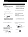
DRAIN PIPING
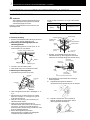
4. DRAIN PIPING
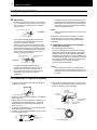
4.1. GENERAL
CAUTION:
- Do not create an upper-slope or rise for the drain
piping, since drain water will flow back to the unit and
leakage to the room will occur when the unit
operation is stopped.
- Do not connect the drain pipe with sanitary or sewage
piping or any other drainage piping.
- When the common drain piping is connected with
other indoor units, the connected position of each
indoor unit must be higher than the common piping.
The pipe size of the common drain pipe must be large
enough according to the unit size and number of unit.
- Drain piping will require insulating if the drain is
installed in a location where condensation forming on
the outside of drain pipe may drop and cause
damage. The insulation for the drain pipe must be
selected to insure vapor sealing and prevent
condensation forming.
- Drain trap should be installed next to indoor unit. This
trap must be designed to good practice and be
checked with water (charged) and tested for correct
flow. Do not tie or clamp the drain pipe and refrigerant
pipe together.
NOTE:
Install drainage in accordance with national and local
codes.
After performing drain piping work and electrical wiring,
check to ensure that water flows smoothly as in the
following procedure:
Checking with Drain-Up Mechanism and Float
Switch
- Switch ON the power supply.
- Pour approximately 1.8 liters of water into the drain pan,
then float switch up and drain pump start working
automatically.
- Check to ensure that the water flows smoothly or
whether no water leakage occurs. When water cannot be
found at the end of the drain piping, pour another
approximately 1.8 liters of water into the drain pan.
- Switch OFF the power supply after.
NOTE:
Pay attention to the thickness of the insulation when
the left side piping is performed. If it is too thick,
piping can not be installed in the unit.
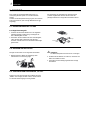
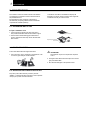
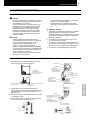
4.2. DRAIN PIPE CONNECTION
1. The position of the drain pipe connection is shown
below.
2. Prepare a polyvinyl chloride pipe with a 32mm outer
diameter.
3. Fasten the tubing to the drain hose with an adhesive
and the factory-supplied clamp. The drain piping must
be performed with a down-slope pitch of 1/25 to 1/100.
4. Do not apply excessive force to the Drain Pipe
connection. It could cause a damage.
5. Do not use a bent or twisted Drain Hose. It will cause
water leakage.
6. Insulate the drain pipe after connecting the drain hose.
Do not use adhesive between the Drain Pipe
Connection and the
IIncorrect: Upward Slope
Incorrect: Rising Part
INCORRECT
Common Drain Piping
1/25~1/100 Down Slope
Drain Piping connection
CORRECT
Max.
850 mm
Drain Piping Connection
1/25~1/100
Down Slope
(Gradient of Drain piping)
Drain Pipe
Connection
Hose Band
(Accessory)
Do not use adhesive
Vinyl Chloride VP25
(Field Supplied
Use Vinyl Chloride type
adhesive
Drain Hose
(Accessory)
Hose Band (Accessory)
Insulation (Field supplied)

5
ELECTRICAL WIRING
5
5. ELECTRICAL WIRING
5.1. GENERAL
Õ DANGER:
- Turn off the main power switch to the indoor unit and
the outdoor unit before electrical wiring work or a
periodical check is performed.
- Check to ensure that the indoor fan and the outdoor
fan have stopped before electrical wiring work or a
periodical check is performed.
- Protect the wires, drain pipe, electrical parts, etc. from
rats or other small animals. If not protected, rats may
gnaw at unprotected parts and at the worst, a fire will
occur.
CAUTION:
- Use twisted shielded pair cable or shield pair cable
for transmission wires between the indoor and the
outdoor units, and connect the shielded part to the
earth screw in the electrical box of the indoor unit as
shown below.
- Wrap the field supplied insulation around the wires,
and plug the wiring connection hole with the seal
material to protect the product from any condensate
water or insects.
- Tightly secure the wires with the cord clamp inside
the indoor unit.
- Lead the wires through the knockout hole in the side
cover when using conduit.
- Secure the cable of the remote control switch using
the cord clamp inside the electrical box.
General Check
1. Make sure that the field-selected electrical components
(main power switches, circuit breakers, wires, conduit
connectors and wire terminals) have been properly
selected. Make sure that the components comply with
National Electrical Code (NEC).
2. Check to ensure that the power supply voltage is within
+10% of the rated voltage.
3. Check the capacity of the electrical wires. If the power
source capacity is too low, the system cannot be started
due to the voltage drop.
4. Check to ensure that the ground wire is connected.
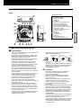
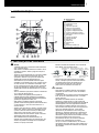
5.2. ELECTRICAL WIRING CONNECTION FOR INDOOR UNIT
1. The electrical wiring connection for the indoor unit is
shown below.
2. Connect the cable of an optional remote control switch
or an optional extension cable to the terminals inside the
electrical box through the connecting hole in the cabinet.
3. Connect the power supply and earth wires to the
terminals in the electrical box.
4. Connect the wires between the indoor unit and the
outdoor unit to the terminals in the electrical box.
Electrical Box
Stopper (Metal)
Power Source Wiring
Transmission Wiring
Remote Control Switch Cable
Transmission Wiring
(between Indoor Unit
and Outdoor Unit)
Remote Control Switch Cable
Screw
Printed Circuit Board
Terminal Board (TB2)
Earth Screw
Terminal Board (TB1)
Printed Circuit Board
Power Source Wiring
Transmission Wiring
(between Indoor Unit and Indoor Unit)
Cord Clamp
Transmission Wiring
(Outdoor Unit to Indoor Unit
and Indoor Unit to Indoor Unit)
Operation Wiring
In case of group control
operation by using a Remote
Control Switch
Remote Control Switch Cable
Power source Wiring
Operating Wiring
Remote Control Switch Cable
Hole for Wiring Connection Ø 32.5
(for Spare)
(Knock-Out Hole)
Hole for Wiring Connection 30x39
(for Cable)
Power Source
(TB2)
CN27
CN28
240V
220V

5
6
ELECTRICAL WIRING
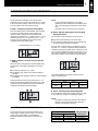
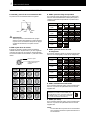
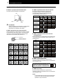
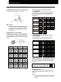
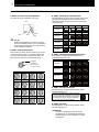
5.3. SETTINGS OF DIP SWITCHES
Quantity and Position of Dip Switches
Dips switches position is the following:
CAUTION:
Before setting dips switches, firstly turn off power
source and set the position of the dips switches. If the
switches are set without turning off the power source,
the contents of the setting are invalid.
RSW: Unit No. Setting
Setting is required. Set the unit No. of all indoor units
respectively and serially, by following setting position
shown in the table below. Numbering must start from “1” for
every indoor unit.
Main Unit 1 st. unit 2 nd. unit 3 rd. unit
4 th. unit 5 th. unit 6 th. unit 7 th. unit
8 th. unit 9 th. unit 10 th. unit 11 th. unit
12 th. unit 13 th. unit 14 th. unit 15 th. unit
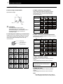
DSW3: Capacity Code Setting
No setting is required, due to setting before shipment. This
dip switch is utilized for setting the capacity code which
corresponds to the Horse Power of the indoor unit.
HP 0.8 1.0 1.3 1.5
Setting Position
ON
1 2 3 4
ON
1 2 3 4
ON
1 2 3 4
ON
1 2 3 4
1.8 2 2.3 2.5
Setting Position
ON
1 2 3 4
ON
1 2 3 4
ON
1 2 3 4
ON
1 2 3 4
2.8 3 3.5 4
Setting Position
ON
1 2 3 4
ON
1 2 3 4
ON
1 2 3 4
ON
1 2 3 4
5 6
Setting Position
ON
1 2 3 4
ON
1 2 3 4
DSW5: Refrigerant Cycle No. Setting
Setting is required. Setting position before shipment is all
OFF (Refrigerant cycle No. 0)
HP 0 1 2 3
Setting Position
ON
1 2 3 4
ON
1 2 3 4
ON
1 2 3 4
ON
1 2 3 4
4 5 6 7
Setting Position
ON
1 2 3 4
ON
1 2 3 4
ON
1 2 3 4
ON
1 2 3 4
8 9 10 11
Setting Position
ON
1 2 3 4
ON
1 2 3 4
ON
1 2 3 4
ON
1 2 3 4
12 13 14 15
Setting Position
ON
1 2 3 4
ON
1 2 3 4
ON
1 2 3 4
ON
1 2 3 4
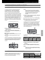
DSW7: Fuse Recover
No setting is required, due to setting before shipment.
Setting position before shipment is all OFF.
In case of applying high voltage to the terminal
1,2 of TB2, the fuse (0.5) on the PCB1(M) is cut.
In such a case, firstly correct the wiring to TB2
and then turn ON #1 (as showing beside)
ON
1 2
DSW8: (Not used)
No setting is required, due to setting before shipment.
Setting position before shipment is all OFF.
NOTE:
- The mark ““ indicates position of dips switches.
Figures show setting before shipment or after
selection.
Setting position
Set by inserting a
screwdriver into the
groove.
RSW
DSW7 DSW3 DSW5
DSW8

6
REMOTE CONTROLLER OPERATION
7
6. REMOTE CONTROLLER OPERATION
6.1. SETTING THE FILTER INDICATION INTERVAL
The FILTER interval indication on the remote control
Switch (PC-P1H) can be set a approximately 100, 1,200 or
2,500 hours (factory setting: 1,200 hours). If 100 or 2,500
hours is required, follow the instructions below.
Step 1: Changing to Optional Setting Mode
Press the CHECK switch and the RESET switch together
more than 3 seconds while the unit is stopped. The
operation mode is changed to the field setting mode,
“SERVICE” is indicated and “
” flickers. When “” is not
indicated, press the < or = switch and set “”. In this
condition, press the CHECK switch and the mode is
changed to the optional setting mode.
Step 2: Selection of Indoor Unit for Optional
Setting
When the mode is changed to the optional setting mode,
the indication on the liquid crystal display is as shown
below.
The flickering indication of “
“stops.
The address of the Indoor Unit for optional setting is
indicated.
The address of the refrigerant system for optional setting
is indicated.
Select the Indoor Unit to be set by pressing the < or =
switch and indicate the address of the Indoor Unit. In this
condition, press the CHECK switch and the indication is
changed to the indication of optional setting:
NOTE:
- In case that the both indications of the ADDS.
(Address) and RN. (Refrigerant Cycle Number) show
“”, the same setting is performed to all the indoor
units.
- The indoor units not connected are not indicated.
Step 3: Optional Setting Items and Changing
Setting Conditions
The indication of optional setting is as shown below.
The code of optional setting is as shown below
The indications of ADDS. and RN. are turned OFF and
the optional setting condition is indicated.
The item code of optional setting is changed by pressing
the TIME < or = switch. The optional setting condition is
changed by pressing the CHECK switch. Set the item code
“)”. In case of setting other indoor unit, press the < or =
switch and the indication is changed to the condition of the
item “Step 2 Selection of Indoor Unit for Optional Setting”.
The relation between the indication and the interval is
shown in the table below.
FILTER Indication Interval
Approx. 100hr.
Approx.
1,200hr.
Approx.
2,500hr.
No indication
b4 01
b4 02
B4 00 (*)
b4 03 b4 04
(*) Standard
Step 4: Cancelling Optional Setting Mode
Press the RESET switch in the condition of Step 2 or Step
3, the condition is changed to the standard condition.
NOTE:
The Label for checking the contents of the setting is
attached to the holding bracket. Write down the
contents of the setting on the label.
6.2. SETTING OF HIGH SPEED TAP
The air flow volume can be changed according to the
ceiling height by setting the item code to “C5” form the
remote control switch (Refer to the Installation &
Maintenance Manual of the remote control switch for
details).
Ceiling Height
1.0 to 2.5HP 3.0 to 6.0HP
Setting of Remote
Control Switch
Below 2.7m Below 3.2m Standard
2.7 to 3.0m 3.2 to 3.6m High Speed (1)
3.0 to 3.5m 3.6 to 4.2m High Speed (2)
Flickered (Press < or = switch)

7
8
INSTALLATION OF OPTIONAL AIR PANEL: P-G23WA2
7. INSTALLATION OF OPTIONAL AIR PANEL: P-G23WA2
7.1. FACTORY-SUPPLIED ACCESSORIES
CAUTION:
When the air panel is unpacked, place it on insulation
material, etc. to protect the sealing insulation from
scratches
Check to ensure that the following accessories are packed
with the air panel.
If any of these accessories are not packed in the packing,
please contact your contractor.
Accessory Quantity Purpose
Long Screw
(M6×50)
4 For Fixing Panel
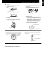
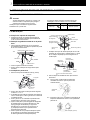
7.2. INSTALLATION
Location of Suspension Brackets
1. Check to ensure that the suspension brackets of the
indoor unit are located approximately 102mm higher the
false ceiling.
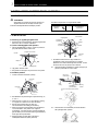
Removing Air Intake Grille from Air Panel.
1. Open the air intake grille to an angle of approximately
45º from the surface of the air panel as shown below.
2. Lift the grille keeping it inclined
3. Draw the grille towards the open space after lifting.
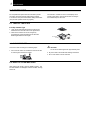
Installing Air Panel
1. Remove the cover of the corner pocket (4 portions).
b
a
c
d
2. Pull the fixing nail towards the arrow mark according to
the order ”a”, ”b” and ”c”.
3. The corner pocket can be lifted. After lifting, move it in
”d” direction, disconnect the L type hook and dismantle
the corner pocket.
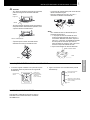
4. Pull down theU-shaped hook (at 2 positions) located at
the indoor unit side.
5. Set the corner fo the refrigerant connection portion of
the indoor unit to the position indicated as ”Ref. Piping”,
and hook the C-shapped hinge (2 positions) onto the U-
shapped hooks (2 positions) so that temporary
positioning is available.
6. Mount the air panel onto the air panel fixing position by
using the factory-supplied fixing screws (M6 cross
screws)
7. Check to ensure that there is no gap around the
conctacting surface between the indoor unit and the air
panel. Any gap may cause air leakage or dewing.
8. Attach the corner pocket covers after mounting air
panel:
8.1. Hook the band at the rear side of the cover for the
corner pockets onto the pin of the panel as shown
below.
8.2. Hook the L-shapped nail located at the rear side of
the cover for the corner pockets onto the square hole of
the air panel.
Correct
45º
A
ir Intake Grille
A
ir Filte
r
A
ir Panel
Wrong
Ceiling
Take u
p
the
g
rille kee
p
in
g
it inclined
Pin
Band
L-shaped Nail
Fixing Nail (3 Portions)
Fixing Nail
Fixing Nail
Fixing Nail
L-Type Hook
Indoor Unit
Hook
Fixing Plate
A
ir Panel
Long Screw
(Q’ty 4)
Electrical Control
Box
Refrigerant Pipe
Connections
Stamp
“Ref Pipe”
U-shaped Hook
(Q’ty 2)
Long Screw
Fixing Plate
(
Indoor Unit Side
)
Sealing
Gasket
Indoor Unit
Undersurface
False
Ceilin
g
Panel
Fixing Plate
(
Air Panel Side
)
*
:Fix screw until this end touches it.
*

7
INSTALLATION OF OPTIONAL AIR PANEL: P-G23WA2
9
CAUTION:
- If tighten long screws insufficient, may cause
something wrong as below.
- If any gap has even though tighten long screws
sufficient, readjust the height of indoor unit.
- It’s able to adjust the indoor unit height by using
wrench from the corner pocket.
- Too considerable adjustment of height cause dewing
from drain-pain.
- Do not turn the air louver by hand. If moved, the
louver mechanism would be damaged.
NOTE:
In case that the corner pocket is dismantled agter
installing the air panel:
1. ”1” The corner position of the corner pocket ca be
lifted by inserting a ”- ” shaped driver and lifting.
By keeping this state, lift the ”-” shaped driver in
the lower direction. The whole corner pocket can
be lifted. After disconnecting the fixing nails (3
positions), disconnect the L-shaped nail and
remove the corner poc1ket cover.
2. Slide the cover in the allowed direction.
7.3. WIRING CONNECTION FOR AIR PANEL
1. The following connector is used with the air panel (view
from lower surface of air panel without air intake grille)
2. Connect the connectors as shown below (view of the
electrical box)
7.4. TEST RUN
After completing the installation of the air panel, a test run
should be performed by refering to I&O PMML0101A.
A
ir Leakage
Smudge Dewing
No gap shall exist
Electrical Control
Box
Connector for Auto
Swing Motor
(Low Voltage,
7Pin, Red)
Electrical Control Box for Indoor
Unit
PCB
Connector for Auto Swing Motor
(Low Voltage, 7Pin, Red)
CN17
Wrench
Coin or Slotted Screwdriver
Corner Position
Lifting
Louver

8
10
MAINTENANCE
8. MAINTENANCE
Do not operate the system without the air filter to protect
the indoor unit heat exchanger against being clogged.
Turn OFF the main power switch before taking out the filter.
(The previous operation mode may appear.)
The indication, “FILTER” is shown on the display of the
remote control switch. Take out the air filter according to
the indicated steps for each unit.
8.1. TAKE OUT THE FILTER
4-Way Cassette Type
1. Open the air inlet grille after pushing the two knobs
toward the arrow mark as shown in the figure below.
2. Take out the air filter from the air inlet grille by
supporting the air grille and lifting the air filter after
detaching the filter from two hinges
8.2. CLEAN THE FILTER
Clean the air filter according to the following steps:
1. Use a vacuum cleaner or let water flow onto the air filter
for removing the dirt from the air filter.
CAUTION:
Do not use hot water higher than approximately 40ªC
2. Dry the air filter in the shade after shaking off moisture.
3. Do not use cleaner or other chemicals
8.3. RESET OF FILTER INDICATION
After cleaning the air filter, press the “RESET” button. The
FILTER indication will disappear and the next filter cleaning
time is set.
Knob
A
ir Inlet Grille
A
ir Filter
A
ir Inlet Grille
Chain
Hinges

1
NOMBRES DE LAS PIEZAS
1
1. NOMBRES DE LAS PIEZAS
RCI
Nº Nombre de la pieza
1 Ventilador
2 Motor del ventilador
3 Intercambiador de calor
4 Distribuidor
5 Válvula de expansión
6 Caja eléctrica
7 Conexión del gas refrigerante
8 Conexión del líquido refrigerante
9 Conexión de la tubería de desagüe
10
Motor para el mecanismo de descarga del
desagüe
11 Interruptor de flotador
12 Bandeja de desagüe
13 Panel P-G23WA2
14 Filtro de aire
15 Salida de aire
16 Entrada de aire
17 Filtro
18 Rejilla de entrada de aire
19 Tapa para esquina
2. INSTALACIÓN DE LAS UNIDADES
Ô ADVERTENCIA:
- Compruebe que los accesorios se han incluido
con la unidad interior.
- No instale las unidades interiores en el exterior. Si las
instala en el exterior, podrían derivarse riesgos o
producirse fugas eléctricas.
- Tenga en cuenta la distribución de aire desde cada
unidad interior hacia el espacio de la habitación y
seleccione una ubicación adecuada para obtener una
temperatura uniforme del aire en la habitación. Se
recomienda instalar las unidades interiores a una
distancia comprendida entre 2,3 y 3 metros del nivel
del suelo. Si la unidad se instala a una altura superior
a 3 metros, se recomienda utilizar un ventilador para
obtener una temperatura uniforme del aire en la
habitación.
- Evite los obstáculos que puedan obstruir la entrada
de aire o su caudal de descarga.
- Tenga en cuenta los siguientes puntos cuando instale
las unidades interiores en un hospital u otros lugares
en los que existan ondas electrónicas procedentes de
equipos médicos, por ejemplo.
- No instale las unidades interiores donde las ondas
electromagnéticas se irradien directamente a la caja
eléctrica, el control remoto o el cable de éste.
- Prepare una caja de acero e instale en ella el control
remoto. Prepare un conducto de acero y tienda el
cable del control remoto en el mismo. A continuación,
conecte el cable de tierra a la caja y al tubo.
- Instale un filtro de ruido en caso de que la fuente de
alimentación emita ruidos molestos.
- Este tipo de unidad interior no utiliza un calentador
eléctrico. Está prohibido instalar un calentador
eléctrico en el lugar de instalación.
- Monte los pernos de suspensión usando el tamaño
M10 (W3/8) como se indica a continuación:
- No coloque materiales extraños en la unidad interior
y asegúrese de que ésta no tiene ninguno en su
interior antes de instalarla y de realizar la prueba de
funcionamiento. De lo contrario, pueden producirse
fallos, incendios, etc.
PRECAUCIÓN:
- No instale las unidades interiores en entornos
inflamables para evitar riesgos de incendio o explosión.
- Asegúrese de que el techo es suficientemente
resistente. De lo contrario, la unidad puede caer
sobre usted.
- Instale las unidades interiores, la unidad exterior, el
control remoto y el cable a una distancia mínima de
3 metros aproximadamente de radiaciones fuertes de
ondas electromagnéticas (por ejemplo, las generadas
por equipos médicos).
- No instale las unidades interiores en una cocina o taller
de maquinaria donde el vapor de aceites o brumas
fluya hacia las unidades. El aceite se depositará en
el intercambiador de calor, lo que puede reducir el
rendimiento de la unidad y causar deformaciones.
En el peor de los casos, el aceite puede dañar las
piezas de plástico de la unidad interior.
- Para evitar la corrosión de los intercambiadores de
calor, no instale las unidades interiores en entornos
ácidos o alcalinos.
- Cuando levante o traslade la unidad interior, emplee
eslingas adecuadas para evitar daños y asegúrese
de no dañar el material aislante de la superficie de
las unidades.
A
randelas
cuadradas
Barra de madera
(60 a 90 mm
2
)
Viga de madera
Perno de eslinga
(W3/8 o M10)
Para losa de hormigón de
150~160 mm
Hormigón
Perno de
anclaje
A
cero
Viga en I
Pernos de suspensión
(W3/8 o M10)
Tuercas

2
2
INSTALACIÓN DE LAS UNIDADES
2.1. INSTALACIÓN DE LA UNIDAD
2.1.1. ACCESORIOS SUMINISTRADOS
DE FÁBRICA
Accesorio Cant. Utilización
Patrón
(cartón)
1
Para ajustar el espacio
entre la apertura del
falso techo y la posición
de la unidad
Tornillos
de cabeza
con estribo
cruciforme
4 Para ajustar el patrón
Arandela con
aislamiento
4
Arandela
(M10)
4
Para la instalación
de la unidad
Tubo de
desagüe
1
Abrazadera
de alambre
2
Para la conexión del
tubo de desagüe
Reductor 1
Para
RCI-(4.0/5.0/6.0)FSN1E
(sólo R410A)
2.1.2. COMPROBACIÓN INICIAL
- Instale la unidad interior dejando una distancia suficiente
a su alrededor y prestando especial atención a la dirección
de instalación de las tuberías, el cableado y el espacio
para mantenimiento, como se indica a continuación.
- Proporcione una puerta de acceso de servicio cerca del
área de conexión de las tuberías situada en el techo.
Espacio para servicio
-
Compruebe que hay espacio suficiente entre el techo y
el falso techo, como se muestra a continuación.
- Asegúrese de que la superficie del techo sea plana para
poder instalar el panel de aire.
HP de la unidad A (mm)
RCI-1.0 a 2.5HP 248
RCI-3.0 a 6.0HP 298
- Compruebe que la inclinación descendente de la tubería
de desagüe sigue las especificaciones indicadas en
el capítulo Tubería de desagüe.
Abertura en el falso techo
- Recorte el área de la unidad interior en el falso techo
e instale los pernos de suspensión como se indica
a continuación:
- Asegúrese de que el techo está nivelado horizontalmente;
de lo contrario el agua no podrá fluir.
- Refuerce la abertura del falso techo.
2.1.3. INSTALACIÓN
Montaje de los pernos de suspensión
- Monte los pernos de suspensión como se indica
a continuación.
Para losa de hormigón:
Para viga de acero:
Montaje de la unidad interior
- Monte las tuercas y las arandelas en los pernos de
suspensión. Coloque la arandela de tal forma que
la superficie con aislamiento pueda quedar orientada
hacia abajo, como se muestra a continuación:
- Tenga en cuenta el lateral para la conexión de
las tuberías antes de izar la unidad interior.
- Levante la unidad con el cable de izar sin ejercer presión
en la bandeja de desagüe.
- Sujete la unidad interior con las tuercas y las arandelas.
Conexión
de las
tuberías
Puerta de acceso
de servicio
Puerta de acceso de servicio
Distancia:
10-20 mm
A
ltura de
la unidad en
el falso techo
Conexión de la tubería de gas
Pernos de suspensión (4)
Falso techo
Conexión de la tubería de desagüe
Tubería de líquido
Panel
(para su posterior instalación, sólo se
muestra como referencia)
Orificio para el cableado (30x30)
A
bra el orificio perforable para
el cableado (Ø 32,5)
Soporte de suspensión
150 a 160 mm Inserción (100 a 150 kg)
Hormigón en I
Perno de anclaje (W3/8 o M10)
Acero
Viga en I
Perno de suspensión
(w3/8 o M10)
Dimensión de pernos de
suspensión: 760
4 posiciones de pernos
de suspensión
Dimensión de la abertura: 860 a 910
Lado de conexión de
las tuberías
Tubería de desagüe
Lado de conexión
Panel opcional
Tamaño de unidad: 840
Dimensión de la abertura: 860 a 910
Tamaño de unidad: 840
Dimensión de pernos de
suspensión: 760
(mm)
Pernos de suspensión (suministrados por el instalador)
Tuerca (suministrada por el instalador)
A
randela con aislante (accesorio)
A
randela (accesorio)
Tuerca (suministrada por el instalador)
Soporte de suspensión (unidad interior conectada)
Superficie del techo
A
prox. 50
102
A
prox. 52
(mm)
500 mm Min.
500 mm Min.
100 mm Min.
100 mm Min.
1000 mm Min.
Lado de conexión
de las tuberías

3
TUBERÍAS DE REFRIGERANTE
3
NOTA:
- Si ya se ha instalado un falso techo, coloque
las tuberías y los cables en el mismo antes de
enganchar la unidad interior.
- Sujete la unidad empleando las tuercas, las
arandelas planas y las arandelas de resorte.
(Se suministran 4 piezas de cada).
Ajuste del espacio entre las unidades
interiores y la abertura del falso techo
- Compruebe el nivel de la bandeja de desagüe con un
nivelador de agua para que el mecanismo de descarga
pueda funcionar correctamente en la unidad interior.
- Apriete las tuercas de los soportes de suspensión una
vez realizado el ajuste. Aplique pintura LOCK-TIGHT
en los pernos y las tuercas para evitar que se aflojen.
De lo contrario, pueden producirse sonidos extraños y
la unidad interior podría aflojarse.
- Ajuste la unidad interior en la posición correcta utilizando
el patrón para la instalación.
1. Para techos que ya tengan paneles.
2. Para techos sin paneles.
3. TUBERÍAS DE REFRIGERANTE
3.1. CONEXIÓN DE TUBERÍAS
3.1.1. POSICIÓN DE LAS TUBERÍAS
A continuación se muestra la posición de la conexión de
la tubería, que está disponible en todas las direcciones
(superior, izquierda o derecha).
3.1.2. TAMAÑO DE CONEXIÓN DE TUBERÍAS
En caso de R407C
(mm)
Modelo RCI 1.0/1.5 2.0 2.5/3.0/3.5 4.0/5.0/6.0
o
Tubería
de gas
12,7 15,88 15,88 19,05
p
Tubería
de líquido
6,35 6,35 9,53 9,53
En caso de R410A
(mm)
Modelo RCI 1.0/1.5 2.0 2.5/3.0/3.5 4.0/5.0/6.0
o
Tubería
de gas
12,7 15,88 15,88 15,88
p
Tubería
de líquido
6,35 6,35 9,53 9,53
Instrucciones especiales para R410A
Debido a que la presión del R410A es alrededor de
1,4 veces más elevada que la del R407C, una instalación
inadecuada puede ocasionar un problema grave.
Es necesario utilizar las tuberías de cobre, el tamaño de los
extremos de las tuberías cónicas y las tuercas cónicas que
se muestran a continuación.
Dimensiones de las tuberías cónicas
(mm)
A
+0/-0,4
Diámetros
nominales
Diámetros
exteriores
R407C R410A
1/4 6,35 9,0 9,1
3/8 9,53 13,0 13,2
1/2 12,70 16,2 16,6
5/8 15,88 19,4 19,7
Grosor de las tuberías de cobre
(mm)
Diámetros
nominales
Diámetros
exteriores
R407C R410A
1/4 6,35 0,80 0,80
3/8 9,53 0,80 0,80
1/2 12,70 0,80 0,80
5/8 15,88 1,00 1,00
Dimensiones de tuercas cónicas
(mm)
B
Diámetros
nominales
Diámetros
exteriores
R407C R410A
1/4 6,35 17 17
3/8 9,53 22 22
1/2 12,70 24 26
5/8 15,88 27/29 29
Unidad interior
A
juste este lado
de la escala en el
panel del techo
A
juste este lado de la escala
al lado inferior de la unidad
Compruebe la altura del
techo en cada esquina
de la unidad
Escala de
comprobación
A
juste este lado de la escala en el lado
interno de la abertura del techo
A
juste este lado
de la escala en
el lado exterior
de la unidad
Unidad interior
Escala de
comprobación
Panel
del techo
Compruebe las
dimensiones de la abertura
a cada lado de la unidad
Patrón para la instalación
Embalaje
(cartón corrugado)
Comprobación de la escala para
las dimensiones de la abertura
UnitUnitUnit
Tamaño de la abertura
Tamaño de la abertura
Patrón para l
la instalación
Tornillo (M6)
Superficie del techo
Perno de suspensión
Patrón para la instalación
Unidad

4
4
TUBERÍA DE DESAGÜE
4. TUBERÍA DE DESAGÜE
4.1. GENERAL
PRECAUCIÓN:
- No cree una inclinación ascendente ni una elevación
para la tubería de desagüe, ya que el agua volverá a
fluir a la unidad y provocará fugas en la habitación
cuando se pare.
- No conecte la tubería de desagüe a la tubería de
agua sanitaria ni del alcantarillado, como tampoco
a ninguna otra tubería de desagüe.
- Cuando se conecte la tubería de desagüe común a
otras unidades interiores, la posición de conexión de
cada unidad interior deberá ser más alta que la de la
tubería común. El tamaño de la tubería de desagüe
común debe ser suficientemente grande para el
tamaño y el número de unidades.
- Las tuberías de desagüe deben aislarse si el
desagüe está instalado en un lugar en el que la
condensación que se forme en el exterior de la
tubería pueda causar daños. El material aislante
debe sellar la salida de vapor e impedir la
condensación.
- El dispositivo de retención debe instalarse junto a la
unidad interior. Este dispositivo debe estar diseñado
adecuadamente, comprobarse con agua (cargarse) y
tener el flujo correcto. No fije la tubería de desagüe y
la tubería de refrigerante juntas.
NOTA:
Instale el desagüe de acuerdo con la normativa local
y nacional.
Después de instalar la tubería de desagüe y de realizar
el cableado eléctrico, compruebe que el agua fluye sin
ningún problema, siguiendo el procedimiento descrito a
continuación:
Comprobación con mecanismo de desagüe
e interruptor de flotador
- Encienda la fuente de alimentación.
- Vierta aproximadamente 1,8 litros de agua en la bandeja
de desagüe, suba el interruptor de flotador y la bomba de
desagüe se pondrá en funcionamiento automáticamente.
- Compruebe que el agua fluye sin ningún problema, y que
no existen fugas de agua. Si no sale agua por el extremo
de la tubería de desagüe, vierta otros 1,8 litros de agua
aproximadamente en la bandeja de desagüe.
- Apague la fuente de alimentación.
NOTA:
Tenga cuidado con el grosor del material aislante
cuando se instale la tubería del lado izquierdo. Si es
demasiado grueso, no se podrá instalar la tubería de
la unidad.
4.2. CONEXIÓN DE LA TUBERÍA DE DESAGÜE
1. La posición de la conexión de la tubería de desagüe se
muestra a continuación.
2. Prepare un tubo de cloruro de polivinilo con un diámetro
exterior de 32 mm.
3. Fije la tubería al tubo de desagüe con un adhesivo y con
la abrazadera suministrada de fábrica. La tubería de
desagüe debe tener una inclinación descendente de
entre 1/25 y 1/100.
4. No aplique demasiada fuerza a la conexión de la tubería
de desagüe. Ésta podría dañarse.
5. No utilice un tubo de desagüe doblado o torcido. Podría
ocasionar fugas de agua.
6. Aísle la tubería de desagüe después de conectar el tubo
de desagüe. No utilice adhesivo entre la conexión de la
tubería de desagüe y el tubo de desagüe.
Incorrecto: inclinación ascendente
Incorrecto: parte ascendente
INCORRECTO
Tubería de desagüe común
Inclinación descendente
de 1/25~1/100
Conexión de la tubería
de desagüe
CORRECTO
Máx.
850 mm
Inclinación descendente
de 1/25~1/100
(Gradiente de la tubería de desagüe)
Conexión De La Tubería
Drain Pipe
Connection
Hose Band
(Accessory)
Do not use adhesive
Vinyl Chloride VP25
(Field Supplied)
Use Vinyl Chloride
type adhesive
Drain Hose
(Accessory)
Hose Band (Accessory)
Insulation (Field supplied)

5
CABLEADO ELÉCTRICO
5
5. CABLEADO ELÉCTRICO
5.1. GENERAL
Õ PELIGRO:
- Apague el interruptor de alimentación principal
de la unidad interior y la unidad exterior antes de
llevar a cabo tareas de cableado eléctrico o una
comprobación periódica.
- Asegúrese de que el ventilador interior y el exterior
se han parado antes de llevar a cabo tareas de
cableado eléctrico o una comprobación periódica.
- Proteja los cables, la tubería de desagüe, las piezas
eléctricas, etc., de las ratas u otros animales
pequeños. De lo contrario, las ratas podrán roer
las partes no protegidas y, en el peor de los casos,
podría producirse un incendio.
PRECAUCIÓN:
- Utilice cable de par trenzado blindado o cable de par
blindado para los hilos de transmisión entre las
unidades interiores y exteriores, y conecte la parte
blindada al tornillo de tierra en la caja eléctrica de la
unidad interior tal y como se muestra a continuación.
- Enrolle el material aislante suministrado por el
instalador alrededor de los hilos y tape el orificio de
conexión del cableado con el material de sellado para
proteger el producto del agua condensada o de los
insectos.
- Sujete firmemente los hilos con la abrazadera dentro
de la unidad interior.
- Introduzca los hilos a través del orificio perforable
de la tapa lateral cuando utilice un conducto.
- Sujete el cable del control remoto con la abrazadera
del interior de la caja eléctrica.
Comprobación general
1. Asegúrese de que los componentes eléctricos
seleccionados por el instalador (interruptores de
alimentación principal, disyuntores, cables, conectores
de tuberías y terminales de cables) se han seleccionado
correctamente. Cerciórese de que los componentes
cumplen el reglamento nacional de instalaciones
eléctricas (NEC).
2. Compruebe que la tensión de la fuente de alimentación
está dentro del +10% de la tensión nominal.
3. Verifique la capacidad de los cables eléctricos. Si la
capacidad de la fuente de alimentación es demasiado
baja, el sistema no se pondrá en marcha debido a la
caída de la tensión.
4. Compruebe que el cable de tierra está conectado.
5.2. CONEXIÓN DEL CABLEADO ELÉCTRICO DE LA UNIDAD INTERIOR
1. La conexión del cableado eléctrico de la unidad interior
se muestra a continuación.
2. Conecte el cable de un control remoto opcional o un
cable de extensión opcional a los terminales dentro
de la caja eléctrica a través del orificio de conexión
del armario.
3. Conecte la fuente de alimentación y los hilos de tierra
a los terminales de la caja eléctrica.
4. Conecte los hilos entre la unidad interior y la unidad
exterior a los terminales de la caja eléctrica.
Caja eléctrica
Tope (metal)
Cableado de la fuente
de alimentación
Cables de transmisión
Cable del control remoto
Cables de transmisión
(entre la unidad interior
y la unidad exterior)
Cable del control remoto
Tornillo
Tarjeta de circuitos impresos
Cuadro de terminales (TB2)
Tornillo de tierra
Cuadro de terminales (TB1)
Tarjeta de circuitos
impresos
Cableado de la fuente de alimentación
Cables de transmisión
(entre unidad interior y unidad interior)
A
brazadera del cable
Cables de transmisión (de
unidad exterior a unidad
interior y de unidad
interior a unidad interior)
Cableado de servicio
En caso de control de grupos
utilizando un control remoto
Cable del control remoto
Cableado de alimentación
Cableado de servicio
Cable del control remoto
Orificio para la conexión del cableado
Ø 32,5 (para repuesto)
(orificio perforable)
Orificio para la conexión del
cableado de 30x39 (para cable)
Fuente de alimentación
(TB2)
CN27
CN28
240V
220V

5
6
CABLEADO ELÉCTRICO
5.3. AJUSTES DE LOS CONMUTADORES DIP
Cantidad y posición de los conmutadores DIP
La posición de los conmutadores DIP es la siguiente:
PRECAUCIÓN:
Antes de ajustar los conmutadores DIP, apague
primero la fuente de alimentación y realice entonces
el ajuste. Si los conmutadores se ajustan sin apagar
la fuente de alimentación, los ajustes no serán
válidos.
RSW: ajuste del nº de unidad
El ajuste es necesario. Ajuste el número de todas las
unidades interiores respectivamente y en serie, siguiendo
la posición de ajuste que se muestra en la siguiente tabla.
La numeración debe comenzar desde “1” para cada unidad
interior.
Unidad
principal
1ª unidad 2ª unidad 3ª unidad
4ª unidad 5ª unidad 6ª unidad 7ª unidad
8ª unidad 9ª unidad 10ª unidad 11ª unidad
12ª unidad 13ª unidad 14ª unidad 15ª unidad
DSW3: ajuste de código de capacidad
No se precisa ningún ajuste puesto que se realiza antes
del envío. Este conmutador DIP se utiliza para ajustar el
código de capacidad correspondiente a la potencia de la
unidad interior.
HP 0.8 1.0 1.3 1.5
Posición de
ajuste
ON
1 2 3 4
ON
1 2 3 4
ON
1 2 3 4
ON
1 2 3 4
1.8 2 2.3 2.5
Posición de
ajuste
ON
1 2 3 4
ON
1 2 3 4
ON
1 2 3 4
ON
1 2 3 4
2.8 3 3.5 4
Posición de
ajuste
ON
1 2 3 4
ON
1 2 3 4
ON
1 2 3 4
ON
1 2 3 4
5 6
Posición de
ajuste
ON
1 2 3 4
ON
1 2 3 4
DSW5: ajuste del número de ciclo
de refrigerante
Es necesario realizar el ajuste. La posición de ajuste antes
del envío es todo apagado (nº 0 del ciclo de refrigerante).
HP 0 1 2 3
Posición de
ajuste
ON
1 2 3 4
ON
1 2 3 4
ON
1 2 3 4
ON
1 2 3 4
4 5 6 7
Posición de
ajuste
ON
1 2 3 4
ON
1 2 3 4
ON
1 2 3 4
ON
1 2 3 4
8 9 10 11
Posición de
ajuste
ON
1 2 3 4
ON
1 2 3 4
ON
1 2 3 4
ON
1 2 3 4
12 13 14 15
Posición de
ajuste
ON
1 2 3 4
ON
1 2 3 4
ON
1 2 3 4
ON
1 2 3 4
DSW7: restablecimiento del fusible
No es necesario realizar el ajuste, ya que se realiza antes
del envío. La posición de ajuste antes del envío es todo
apagado OFF.
En caso de aplicar una tensión elevada en los
terminales 1,2 de TB2, se corta el fusible (0,5)
en PCB1(M). En tal caso, conecte en primer lugar
el cableado a TB2 y, a continuación, encienda el
nº 1 (como se muestra en la ilustración)
ON
1 2
DSW8: (No usado)
No es necesario realizar el ajuste, ya que se realiza antes
del envío. La posición de ajuste antes del envío es todo
apagado OFF.
NOTA:
- La marca “” indica la posición de los conmutadores
DIP. Las figuras muestran el ajuste antes del envío o
tras la selección.
Posición de ajuste
Realice el ajuste insertando
un destornillador en la
hendidura.
RSW
DSW7 DSW3
DSW5
DSW8
La page est en cours de chargement...
La page est en cours de chargement...
La page est en cours de chargement...
La page est en cours de chargement...
La page est en cours de chargement...
La page est en cours de chargement...
La page est en cours de chargement...
La page est en cours de chargement...
La page est en cours de chargement...
La page est en cours de chargement...
La page est en cours de chargement...
La page est en cours de chargement...
La page est en cours de chargement...
La page est en cours de chargement...
La page est en cours de chargement...
La page est en cours de chargement...
La page est en cours de chargement...
La page est en cours de chargement...
La page est en cours de chargement...
La page est en cours de chargement...
La page est en cours de chargement...
La page est en cours de chargement...
La page est en cours de chargement...
La page est en cours de chargement...
La page est en cours de chargement...
La page est en cours de chargement...
La page est en cours de chargement...
La page est en cours de chargement...
La page est en cours de chargement...
La page est en cours de chargement...
La page est en cours de chargement...
La page est en cours de chargement...
La page est en cours de chargement...
La page est en cours de chargement...
La page est en cours de chargement...
La page est en cours de chargement...
La page est en cours de chargement...
La page est en cours de chargement...
La page est en cours de chargement...
La page est en cours de chargement...
La page est en cours de chargement...
La page est en cours de chargement...
La page est en cours de chargement...
La page est en cours de chargement...
La page est en cours de chargement...
La page est en cours de chargement...
La page est en cours de chargement...
La page est en cours de chargement...
La page est en cours de chargement...
La page est en cours de chargement...
La page est en cours de chargement...
La page est en cours de chargement...
La page est en cours de chargement...
La page est en cours de chargement...
La page est en cours de chargement...
La page est en cours de chargement...
La page est en cours de chargement...
La page est en cours de chargement...
La page est en cours de chargement...
La page est en cours de chargement...
La page est en cours de chargement...
La page est en cours de chargement...
La page est en cours de chargement...
La page est en cours de chargement...
La page est en cours de chargement...
La page est en cours de chargement...
La page est en cours de chargement...
La page est en cours de chargement...
La page est en cours de chargement...
La page est en cours de chargement...
La page est en cours de chargement...
La page est en cours de chargement...
La page est en cours de chargement...
La page est en cours de chargement...
La page est en cours de chargement...
La page est en cours de chargement...
La page est en cours de chargement...
La page est en cours de chargement...
La page est en cours de chargement...
La page est en cours de chargement...
La page est en cours de chargement...
La page est en cours de chargement...
La page est en cours de chargement...
La page est en cours de chargement...
La page est en cours de chargement...
La page est en cours de chargement...
-
 1
1
-
 2
2
-
 3
3
-
 4
4
-
 5
5
-
 6
6
-
 7
7
-
 8
8
-
 9
9
-
 10
10
-
 11
11
-
 12
12
-
 13
13
-
 14
14
-
 15
15
-
 16
16
-
 17
17
-
 18
18
-
 19
19
-
 20
20
-
 21
21
-
 22
22
-
 23
23
-
 24
24
-
 25
25
-
 26
26
-
 27
27
-
 28
28
-
 29
29
-
 30
30
-
 31
31
-
 32
32
-
 33
33
-
 34
34
-
 35
35
-
 36
36
-
 37
37
-
 38
38
-
 39
39
-
 40
40
-
 41
41
-
 42
42
-
 43
43
-
 44
44
-
 45
45
-
 46
46
-
 47
47
-
 48
48
-
 49
49
-
 50
50
-
 51
51
-
 52
52
-
 53
53
-
 54
54
-
 55
55
-
 56
56
-
 57
57
-
 58
58
-
 59
59
-
 60
60
-
 61
61
-
 62
62
-
 63
63
-
 64
64
-
 65
65
-
 66
66
-
 67
67
-
 68
68
-
 69
69
-
 70
70
-
 71
71
-
 72
72
-
 73
73
-
 74
74
-
 75
75
-
 76
76
-
 77
77
-
 78
78
-
 79
79
-
 80
80
-
 81
81
-
 82
82
-
 83
83
-
 84
84
-
 85
85
-
 86
86
-
 87
87
-
 88
88
-
 89
89
-
 90
90
-
 91
91
-
 92
92
-
 93
93
-
 94
94
-
 95
95
-
 96
96
-
 97
97
-
 98
98
-
 99
99
-
 100
100
-
 101
101
-
 102
102
-
 103
103
-
 104
104
-
 105
105
-
 106
106


Hitachi P-G23WA2 Guide d'installation
- Catégorie
- Climatiseurs split-system
- Taper
- Guide d'installation
dans d''autres langues
- italiano: Hitachi P-G23WA2 Guida d'installazione
- English: Hitachi P-G23WA2 Installation guide
- español: Hitachi P-G23WA2 Guía de instalación
- Deutsch: Hitachi P-G23WA2 Installationsanleitung
- Nederlands: Hitachi P-G23WA2 Installatie gids
- português: Hitachi P-G23WA2 Guia de instalação
- dansk: Hitachi P-G23WA2 Installationsvejledning
- svenska: Hitachi P-G23WA2 Installationsguide
Documents connexes
Autres documents
-
Toshiba RBC-UY32P-UL Guide d'installation
-
York Water Source Heat Pump and Heat Recovery Outdoor Units 208-460V Guide d'installation
-
Acson SL30C Guide d'installation
-
 Senville SENL12HDO Mode d'emploi
-
Fujitsu UOMH18AFXZJ Guide d'installation
-
-
Friedrich FPHFC36A3B Mode d'emploi
-
McQuay IM-WMF-0501 Guide d'installation
-
Hama 00047449 Le manuel du propriétaire
