
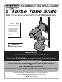
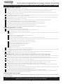
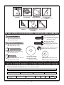
Note: This accessory is designed to fit a 5′ Deck height only.
• Do not climb on the outside
of the slide
• This slide is designed for
home use only, not for
Public Playgrounds
• Product intended for
children ages from 2-10
years old.
C A U T I O N
5′ Turbo Tube Slide
WARNING:
Assembly by an adult.
1-800-882-0272
IMPORTANT!!
PLEASE READ BEFORE BEGINNING ASSEMBLY!!
Please make sure all lumber, hardware and accessory parts are accounted for. If you are missing
anything, please DO NOT RETURN to the store where purchased. Please call our Customer
Service Department at the number below.
To register your product and download unit specific Turbo Tube Slide instructions,
visit:
http://www.swing-n-slide.com
Other benefits include information on product warranties, assembly plan updates, joining our mailing
list for new products and promotions, and providing feedback on products.
Backyard Play Systems • 166 Etowah Industrial Court• Canton, Georgia 30114
ASSEMBLY INSTRUCTIONS
!
LA 8140LDR: 1-22-2020

2
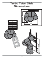
Minimum
Safety Zone
48-1/4"
(122,6 cm)
60"
(152,4 cm)
31-1/2"
(80 cm)
63-1/8"
(160,3 cm)
30"
(76,2 cm)
72"
(182,9 cm)
64"
(162,6 cm)
92"
(233,7cm)
32"
(81,3 cm)
Turbo Tube Slide
Dimensions

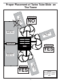
3
This diagram is based
on a 47-1/2’’ square
deck.

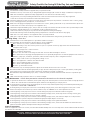
4
Installation Safety – Have You:
Consulted the assembly instructions supplied with your particular model?
Noted this accessory is to be used only on Swing•N•Slide approved designs? (Do not alter its design or add/remove components.)
Made sure all hardware is tightened securely? (Supplied bolt covers must also be fastened securely.)
Using a hacksaw, cut off all protruding threaded ends of bolts and other fasteners and remove any sharp edges with
a metal file as needed, and coated fastener ends with lead free paint?
Placed the equipment on level ground, not less than six feet (1.8 meters) from any structure or obstruction such as a fence, garage,
house, overhanging branches, laundry lines, or electrical wires?
Made sure home playground equipment is not installed over concrete, asphalt, packed earth or any other hard surface? (A fall onto
a hard surface can result in serious injury to the equipment user.)
Verified that suspended climbing ropes, chain,or cable are securely anchored at both ends and cannot be looped back unpon itself?
Consulted in assembly instructions of your particular model for minimum use zones?
Used a water sealant on your play set to protect the wood and prevent cracking and warping?
Followed all anchoring and shock absorbing surfacing requirements on the back of this sheet as they apply?
Made sure not to allow children to use equipment until it is properly installed?
Made sure to adjust all swings so there is a minimum 8'' clearance between the swing and the ground surface?
Operating Safety – Have You:
Determined that on-site adult supervision is provided for children of all ages?
Warned children the following before allowing them to use the equipment?
Not to walk close to, in front of, behind or between moving items.
Not to twist swing or any other accessory chains or ropes or loop them over the top support bar since this will reduce the
strength of chain or rope.
Not to swing empty seats or other accessories.
Not to slide down swing chains.
Be sure to sit in the center of the swing seat and other accessories with full weight on the seat.
Not to attach items to the playground equipment that are not specifically designed for use with the equipment such as but not
limited to, jump ropes, clotheslines, pet leashes, cables and chain. They may cause a strangulation hazard.
Not to climb or walk on the top of swing beams, railings or roof.
Not to use equipment in a manner other than intended.
Not to get off equipment while it is in motion.
Not to climb on the equipment when it is wet.
Be sure to go down slides feet first.
Determined that only one child per planned occupant seat should be allowed on this set at one time.
Determined children must be dressed appropriately for play. Avoid hooded jackets, bicycle or other sports helmets, clothing with
draw strings and loose fitting clothes which could become entangled or snagged on equipment.
Determined that suspended climbing ropes, chain, or cable are securely anchored at both ends and cannot be looped back upon
itself.
Made certain the slide is placed so that is is not in direct sunlight.
Safety Maintenance – Follow these preventive maintenance instructions at the intervals required:
To prevent the deterioration of materials, remove plastic swing seats and other plastic accessories when outdoors temp dips down to
or below 32° F and take indoors. Reinstall these plastic elements at the beginning of each play season.
At the beginning of each play season check metal parts for rust. If found, sand and repaint using a non lead-based paint meeting the
requirements of 16 CFR 1303 or SOR/2005-109.
At the beginning of each play season and once a month during each play season, check all moving parts for wear, rust or other
deterioration. Replace as needed. If any of these conditions exist, call 1-800-882-0272 to order replacement accessories.
At the beginning of each play season and once a month during each play season lubricate metallic moving parts.
At the beginning of each play season and twice a month during each play season, check all protective coverings on bolts, pipes,
edges, and corners. Replace if they are loose, cracked, or missing.
At the beginning of each play season and twice a month during each play season, rake and check depth of loose fill protective
surfacing material to prevent compaction and maintain appropriate depth. Replace as necessary.
At the beginning of each play season and twice a month during each play season tighten all hardware.
At the beginning of each play season and twice a month during each play season, check all wood members for deterioration and
splinters. Sand down splinters and replace deteriorating wood members.
Disposal Instructions
When the equipment is taken out of service, it must be disassembled and disposed of in such a way that no unreasonable hazards will exist at
the time the set is discarded.
Important! Additional Safety Instructions for all Swing-N-Slide Playground Equipment.
Save this instruction sheet in the event the manufacturer needs to be contacted.
Observing the following statements and warnings reduces the likelihood of serious or fatal injury
Safety Checklist for Swing-N-Slide Play Sets and Accessories

5
This product is intended for single family home/residential use only and not intended for use in any public setting.
Placement in any public setting constitutes a misuse of this product.
IMPORTANT!
ADDITIONAL REQUIRED SAFETY INSTALLATION INSTRUCTIONS
According to ASTM requirements, all kits must be anchored to the ground and, if the unit has a climbing rope, the rope end must be anchored to the ground. If soil conditions
permit stakes to be pulled out easily, cementing into ground is necessary.
•To anchor the unit to the ground, Follow the instructions included in this plan for applying Anchor-It devices to your unit, or use 2" x 4" x 18" (45mm x 95mm x 457mm) pressure-
treated stakes. Pound stakes into ground at least 12" (305mm) at all inside corners of the posts (including A-frame legs and climbing unit posts). Attach with four (4) 16D (3-1/2")
galvanized nails per stake into each tower and/or A-frame upright.
•If the unit has a climbing rope, securely anchor the rope at both ends.
•Once the unit is completely assembled and before children are allowed to play on it, proper shock-absorbing surfacing material must be installed. This may be accomplished by
using loose-fill materials at a sufficient depth. The Consumer Product Safety Commission “Handbook for Public Playground Safety” lists the following materials and required
depths that are sufficient for home/residential application. Supplemental information may be found in ASTM F1292. For fall height protection up to 9 ft. (2.742m) [recommended
for Swing•N•Slide kits]:
LOOSE FILL MATERIAL REQUIRED (UNCOMPRESSED) DEPTH1in. (mm)
Wood Mulch 9" (229mm)
Double Shredded Bark Mulch 9" (229mm)
Uniform Wood Chips 12" (305mm)
These depths were derived from the CPSC Handbook. Swing•N•Slide has not done independent tests to determine these required depths.
When properly installed, shock absorbing material will completely cover the horizontal baseboards on climbing units. This protective surfacing must extend a minimum of 6 ft.
(1.828m) in all directions from the perimeter of the equipment or from the outermost edges of any component. For example, a slide extending beyond the platform must have
protective surfacing at least 6 ft. (1.828mm) out from both sides as well as the end. For swings, the protective surface must extend at least 14 ft. (6m) out from both the back and
front of the swing when the swing is in its rest position.
Swing-N-Slide® MANUFACTURERS LIMITED WARRANTY
Swing-N-Slide® takes great pride in the quality and durability of our products. Our Manufacturer’s Limited Warranty provides confidence and demonstrates our commitment
to providing quality residential playground products.
MANUFACTURER’S LIFETIME LIMITED WARRANTY
Swing-N-Slide® warrants its thermoformed slides and climbing mountains to be free from defects in workmanship and materials, under normal use and conditions, for the
lifetime of the product.
MANUFACTURER’S 5 YEAR LIMITED WARRANTY
Swing-N-Slide® warrants its Custom Ready-to-Build Play Set kits and accessories to be free from defects in workmanship and materials, under normal use and conditions,
for a period of 5 years.
MANUFACTURER’S 5 YEAR LIMITED WARRANTY
Swing-N-Slide® warrants its No-Cut and Wood Complete Ready-to-Assemble Play Set kits against wood rot and termite damage, and to be free from defects in
workmanship and materials, under normal use and conditions, for a period of 5 years for structural wood components.
Cosmetic defects that do not affect the structural integrity of the product, or natural defects of wood such as warping, splitting, checking, twisting, shrinkage, swelling or
any other physical properties of wood that do not present a safety hazard, are not covered by this warranty.
MANUFACTURER’S ONE YEAR WARRANTY
Swing-N-Slide® warrants its canopy roofs and/or tarps, and Timber GLOVE lumber wrap to be free from defects in workmanship and materials, under normal use and
conditions, for a period of one year.
Swing-N-Slide® will repair, or at its discretion, replace any part within the stated warranty period which is defective in workmanship or materials. This decision is subject
to verification of the defect upon delivery of the defective part to Swing-N-Slide® at 166 Etowah Industrial Ct., Canton, Georgia, 30114. Any part(s) returned to Swing-N-Slide®
must have prior approved Return Authorization Number and proof of purchase, including the date of purchase. This warranty is valid only if the product is used for the
purpose for which it was designed and installed at a residential, single family dwelling. This warranty is void if the product is put to commercial or institutional use. This
warranty does not cover (a) products which have been damaged by acts of Nature, negligence, misuse, or accident, or which have been modified or repaired by
unauthorized persons; (b) the cost of labor; or the cost of shipping the product, any part, or any replacement product or part.
Swing-N-Slide® DISCLAIMS ALL OTHER REPRESENTATIONS AND WARRANTIES OF ANY KIND, EXPRESS, IMPLIED, STATUTORY OR OTHERWISE, INCLUDING THE
IMPLIED WARRANTIES OF MERCHANTIBILITY AND FITNESS FOR A PARTICULAR PURPOSE. Swing-N-Slide® WILL NOT BE LIABLE FOR ANY INCIDENTAL OR
CONSEQUENTIAL DAMAGES. This warranty is non-transferable and does not extend to the owners of the product subsequent to the original purchaser. Some states do not
allow limitations on implied warranties or exclusion of incidental or consequential damages, so these restrictions may not be applicable to you. This warranty gives you
specific legal rights. You may also have other rights, which vary from state to state.
This warranty also does not apply to:
•Structures not erected, maintained or inspected in conformance with Swing-N-Slide® installation plans
•Structures that have had parts added or substituted not in conformance with Swing-N-Slide® installation plans
•Parts that have been modified, altered or misused
•Parts that have not been used as designed or intended
•Damage due to acts of Nature, vandalism, abnormal use or abuse as determined by Swing-N-Slide®
For further information on playground safety, the Consumer Product Safety Commission
(CPSC) publishes the Outdoor Home Playground Safety Handbook which can be downloaded for free
from www.cpsc.gov. An additional resource is the American Society of Testing and Materials (ASTM)
Standard Consumer Safety Performance Specification for Home Playground Equipment (ASTM F1148)
which can be purchased and downloaded from www.astm.org.

(1) 2'' x 4'' x 96''
25'' 25'' ''32''32
(1) 2'' x 4'' x 96''
''81''81''81 11-1/4'' 8-1/4'' 8-1/4''
(2) 2'' x 4'' x 96''
LUMBER REQUIRED: (4) 2'' x 4'' x 96''
6
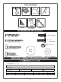
TOOLS REQUIRED
SQUARE
CIRCULAR SAW
DRILL TAPE MEASURE
SAFETY GLASSES
& DUST MASK
1/2” SOCKET & WRENCH
HARDWARE INCLUDED
LUMBER CUT LIST
ADDITIONAL LUMBER PURCHASED SEPARATELY
WRENCH
(18) 2" Lag Screw
(80) 2-1/2" Wood Screw
(2) 2" Wood Screw
(2) 1-1/4" Lag Screw (270) 5/16" Flat Washer
(18) 1/4" x 1-1/4" Fender Washer
(130) 5/16" loc nut
(125) 5/16 x 7/8"
Hex Head Bolt
(8) 5/16 x 1"
Hex Head Bolt

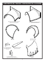
7
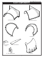
Assembly Instructions
(1) Entrance Piece LH (1) Entrance Piece RH
(9) Elbow (1) Exit Elbow
(1) Exit
(1) Elbow Support
Bracket
(1) Entrance Bracket
SlIDE COMPONENTS
(1) T-Bar Support Bracket

Assembly Instructions
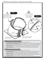
8
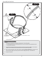
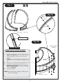
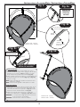
Fig. 1
Entrance Section Assembly
NOTES:
•At least two individuals are needed to assemble the 5' Turbo Tube Slide.
•To aid in aligning holes when assembling sections, insert a screwdriver through adjacent holes
to maintain hole alignment.
1. Assemble the Entrance Section by securing the top seam first, as shown in (Fig. 1). Join sections
using a 7/8" hex head bolt, two flat washers, and a loc nut at each hole junction.
2. When securing the bottom seam make certain to attach the Entrance Bracket to the left side of the
seam as shown in (Fig. 1) securing in place as shown in (Fig. 1a) using 1” hex head bolts.
3. Tighten all hardware.
1"
Hex Head Bolt
7/8" Hex Head Bolts
through plastic flanges
1" Hex Head Bolts
through Bracket
Washer
Washer
Loc Nut
Entrance Section - 8 bolts
Entrance Bracket
Fig. 1a

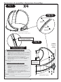
9
Assembly Instructions
Washer
Washer
Loc Nut
Elbow Support
Bracket
Exit Section - 9 bolts
Elbow Section - 9 bolts each
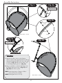
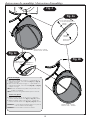
ELBOW AND EXIT SECTION ASSEMBLY
1. Assemble the Elbow Section by securing as shown in
(Fig. 2) and (Fig. 2a). Join sections using a hex head
bolt, two flat washers, and a loc nut at each hole
junction.
NOTE: Fasten each loc nut finger tight. Each time you
join parts be sure each flanged lip is mating with a flat
lip.
2. Repeat step 1 to assemble (3) remaining Elbow Sections.
3. Assemble and secure the Exit Section as shown in
(Fig. 2a) and (Fig. 2b). Make certain to attach the
Elbow Support Bracket to the bottom of the flange,
as shown in (Fig. 2b).
4. Tighten all hardware.
NOTE: Interlocking design of flanges on Elbow pieces
will assist in assembly.
Hex Head Bolt
7/8"
7/8" Hex
Head Bolts

10
Assembly Instructions
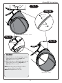
Slide Elbows
1. Align the first elbow section to the Entrance
Section with the seams aligned and the exit facing
downward. Rotate the Elbow (2) holes to the right
as shown in (Fig. 3) and secure in place. Look
for the Flange Opening shown in (Fig. 3a).
2. Align second elbow so that Hole #1 aligns with
the flange opening as shown in (Fig. 3c) and
(Fig. 3d) and secure in place.
NOTE: Interlocking design of flanges on Elbow
pieces will assist in assembly.
NOTE: Hand tighten the loc nuts only.
Elbow Section - 12 bolts
Elbow Section - 12 bolts
Washer
Washer
Loc Nut
Hole #1
Hex Head Bolt
7/8"

11
Assembly Instructions
Washer
Washer
Loc Nut
Fig. 4a
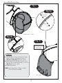
Slide Elbows
1. Align third elbow so that Hole #1 aligns with the
flange opening as shown in (Fig. 4) and
(Fig. 4c) and secure in place.
2. Align fourth elbow so that Hole #1 aligns with the
flange opening, as shown in (Fig. 4b) and
(Fig. 4c) and secure in place.
NOTE: Interlocking design of flanges on Elbow
pieces will assist in assembly.
NOTE: Hand tighten the loc nuts only.
Elbow Section - 12 bolts
Fig. 4
Fig. 4b
Flange Opening
Hole #1
Fig. 4c
Elbow Section - 12 bolts
Hex Head Bolt
7/8"

12
Assembly Instructions
Washer
Washer
Loc Nut
Fig. 5a
Slide Exit
1. Align Exit Elbow Section so that Hole #1 aligns
with the opening in the flange, as shown in
(Fig. 5) and (Fig. 5b) and secure in place.
2. Attach the Exit to the Exit Elbow Section so that
the top of the exit matches the seams, as shown in
(Fig. 5c) and secure in place.
3. Tighten all hardware.
NOTE: Interlocking design of flanges on Elbow
pieces will assist in assembly.
Exit Elbow Section - 12 bolts
Exit - 6 bolts
Fig. 5
Flange Opening
Hole #1
Fig. 5b
Fig. 5c
Align Top Edge of
Slide Base with Exit
Section Seam.
Hex Head Bolt
7/8"

13
Assembly Instructions
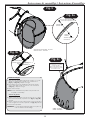
Fig. 6
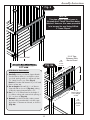
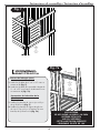
Slide Barrier Construction
1. Carefully remove your Barrier Support Boards
from the barrier where you would like to place
your slide, making certain you will have a clear
72'' Safety Zone for your slide. (Fig. 6).
Retain this lumber and fasteners as you will need
them in a later step.
2. Cut to length and install (2) 2'' x 4'' Barrier
Support Boards as shown in (Fig. 6a), making
certain the opening between them is 25''.
3. Cut (1) 2'' x 4'' Barrier Board to the height of
your barrier railing and create a slide opening of
23'', as shown in (Fig. 6a).
4. Reattach your barrier boards, making certain
they are evenly spaced and do not have a gap
larger than 3'' between each board, as shown in
(Fig. 6a).
Fig. 6a
2-1/2'' screw
2'' x 4''
Cut To Width of Your Unit
(3)
2-1/2''
screws
per joint
25''
23''
3-1/4'' Gap
Between Each
Barrier Board
2'' x 4''
Cut To Width of Your Unit
NOTE:
This plan uses a generic tower to
illustrate the 5' Turbo Tube Slide being
attached. However, this same procedure
is to be used for any Swing-N-Slide
5’ Tower Playset.
5' DECK HEIGHT
2'' x 4''
Barrier Board
Cut to Height
of Rail
(4)
2-1/2''
screws
per barrier
board

14
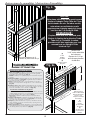
Assembly Instructions
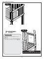
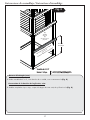
2'' x 4'' x 25''
Fig. 7
INSIDE VIEW
UNIT WAS ROTATED 180˚ FOR THIS VIEW
2'' x 4'' x 23''
(4)
2-1/2'' screws
per board
Fig. 7a
(4)
2-1/2'' screws
per board
Slide Barrier Cont.
1. Install (2) 2'' x 4'' x 25'' Boards as shown in
(Fig. 7).
2. Install (2) 2'' x 4'' x 23'' Slide Support Boards on
the inside of your barrier as shown in (Fig. 7a).
2-1/2'' screw
2'' x 4'' x 25''
2'' x 4'' x 23''

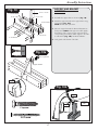
15
Assembly Instructions
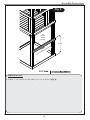
Fig. 8
2'' x 4''
Cut To Width of Your Unit
31-1/2''
Slide Barrier Cont.
1. Install a 2'' x 4'' board, cut to the width of your unit, as shown in (Fig. 8).
(3)
2-1/2''
screws
per joint
2-1/2'' screw

Assembly Instructions
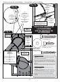
(18)
(12)
2" Lag Screw
(2) 2" Wood Screw
(2) 1-1/4" Lag Screw
1/4" x 1-1/4"
Fender Washer
16
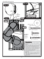
Fig. 9 UNDER DECK VIEW
Fig. 9a Fig. 9b
FLUSH
BRACKET SHOULD BE TIGHT
AGAINST 2" x 4"
Approximate
1-1/4”
Gap
(2)
1-1/4"
Lag Screws
(1)
2" screw
per side
FLUSH
FLUSH
STEP 1
(2)
2" Lag Screws
(2)
1-1/4" Fender
Washers
(2)
2" Lag Screws
(2)
1-1/4" Fender
Washers
2" x 4"
(12)
2” lag screws
Slide Installation
Lift and attach 5' Turbo to units, as shown in
(Fig. 9
1.
2.
3.
).
Note : Two people will be required to properly
align the Turbo Tube Slide with your tower.
On either side of the Slide Entrance there is a
dimple. Insert (1) 2" Screw in either side, so
that the screw goes into the support board
behind, as shown in (Fig. 9a).
Secure Elbow Bracket to 2" x 4" as shown in
(Fig. 9b).
Note : The lower edge of the Elbow Bracket
must sit tightly against the top of the 2" x 4"
support board.

17
Assembly Instructions
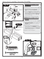
FIGURE 14
2" x 4" x 8-1/4"
2" x 4" x 11-1/4''
2" x 4" x 18" 2" x 4" x 18"
2-1/2" Screws
2-1/2" Screws
2" x 4" x 8-1/4"
(2) 2" Lag Screws
Support Bracket
Fig. 10
Fig. 10a
Fig. 10b
SUPPORT AND BRACKET
ASSEMBLY
1. Assemble the support base as shown in (Fig. 10).
2. Attach the support bracket to the support base using
two lag bolts (Fig. 10a).
NOTE: Pre-drill 1/8" pilot holes.
3. Place the support beneath the Exit and determine its
final position. NOTE: Slide support should fit tightly
beneath the slide to assure proper support. Remove
corresponding nut and bolt, attach support to the slide
as indicated in (Fig. 10b). Re-attach hardware.
4. Level grade at the bottom of the slide.
Pre-Drill
2'' Lag screw
2-1/2'' screw
Loc Nut
Washer
Hex Head
Bolt
FLUSH
2" Lag screw

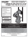
Nota: Este accesorio está diseñado para una altura de plataforma de 5 pies solamente.
Remarque: Cet accessoire est conçu pour s'adapter à une hauteur de pont de 5 pi seulement.
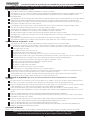
PRECAUCIÓN
• No trepar sobre el lado exterior del tobogán
• Este tobogán fue diseñado únicamente
para ser usado en el hogar,
no en Parques Públicos
• Producto destinado a niños con edades
entre los 2 y los 10 años de edad.
• Los niños deben usar zapatos cerrados al
utilizar este accesorio.
ATTENTION
•Ne grimpez pas sur l’extérieur du toboggan
• Ce toboggan est conçu pour une utilisation
résidentielle uniquement, non pour les aires
de jeux publiques
•Le produit est prévu pour les enfants âgés
de 2 à 10 ans.
• Les enfants doivent porter des chaussures
fermées lorsqu’ils utilisent cet accessoire.
ADVERTENCIA:
El ensamblaje lo
debe hacer un adulto.
1-800-882-0272
¡IMPORTANTE!
¡LEA ANTES DE COMENZAR EL ENSAMBLAJE!
Asegúrese de que todas las piezas de madera, los herrajes y los accesorios estén incluidos. Si falta algo, NO DEVUElVA El KIT a la tienda
donde lo compró. Llame a nuestro Departamento de Servicio al Cliente, al número que aparece abajo.
IMPORTANT!
VEUILLEZ LIRE AVANT DE COMMENCER L’ASSEMBLAGE!
Veuillez vous assurer d’avoir toutes les pièces de bois, de quincaillerie ainsi que tous les accessoires. S’il vous manque quoi que ce soit,
NE RETOURNEZ PAS l’article au magasin où vous l’avez acheté.
Veuillez communiquer avec notre service à la clientèle en téléphonant au numéro ci-dessous.
Para registrar su producto y descargar las instrucciones específicas de la unidad tobogán Turbo Tube, visite:
http://www.swing-n-slide.com
Se incluyen otros beneficios, como información sobre las garantías del producto, actualizaciones del plan de ensamblaje, unirse
a nuestra lista de correo para nuevos productos y promociones y proporcionar comentarios sobre los productos.
Pour enregistrer votre produit et télécharger les instructions particulières à la glissoire Turbo Tube, visitez le site Web :
http://www.swing-n-slide.com
Vous y trouverez également des informations au sujet des garanties des produits, des mises à jour concernant les plans
d’assemblage, et vous pourrez également vous abonner à notre liste d’envoi afin de connaître les nouveaux produits et les
promotions que nous offrons et nous faire part de vos commentaires et suggestions concernant les produits.
Backyard Play Systems • 166 Etowah Industrial Court• Canton, Georgia 30114
Contáctenos en: www.playsupport@back.com o llámenos al
Contactez-nous à: www.playsupport@backyardproducts.com ou téléphonez-nous au
!
! AVERTISSEMENT:
L’assemblage doit être
exécuté par un adulte.
!
INSTRUCCIONES DE ENSAMBLAJE
INSTRUCTIONS D’ASSEMBLAGE
Tobogán de Tubo Turbo de 5' (1,5 m)
Toboggan Turbo Tube de 1,5 m (7 pi)
LA 8140LDR: 1-22-2020

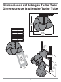
2
Zona mínima de
seguridad
Zone de sécurité
minimale
30 po
(76,2 cm)
30"
(76,2 cm)
72 po
(182,9 cm)
72"
(182,9 cm)
64"
(162,6 cm)
64 po
(162,6 cm)
Dimensiones del tobogán Turbo Tube
Dimensions de la glissoire Turbo Tube
48-1/4"
(122,6 cm)
63-1/8"
(160,3 cm)
48-1/4 po
(122,6 cm)
63-1/8 po
(160,3 cm)
60"
(152,4 cm)
31-1/2"
(80 cm)
31-1/2 po
(80 cm)
92"
(233,7cm)
60 po
(152,4 cm)
92 po
(233,7cm)
32"
(81,3 cm)
32 po
(81,3 cm)

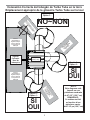
3
Colacación Correcta del tobogán de Turbo Tube en la torre
Emplacement approprié de la glissoire Turbo Tube sur la tour
Opción 1:
Option 1 :
Opción 2:
Option 2 :
Opción 3:
Option 3 :
NOTA:
Este diagrama está
basado en una
plataforma cuadrada
de 47-1/2” (120,7 cm)
REMARQUE :
Ce schéma est fait
en fonction d’une
plate-form carrée
de 47-1/2 po (120,7 cm)
NO~NON
Zona de
Seguridad de la
Viga del Columpio
Zone de sécurité
de la poutre de la
balançoire
Zona de
Seguridad de la
Viga del Columpio
Zone de sécurité
de la poutre de la
balançoire
Viga del
Columpio
Bras de
balançoire
Zona de Seguridad
del Tobogán
Zone de sécurité
du
glissoire
Zona de Seguridad
del Tobogán
Zone de sécurité
du
glissoire
Zona de Seguridad del Tobogán
Zone de sécurité du glissoire
SÍ
OUI
SÍ
OUI
47-1/2”
(120,7 cm)
La page est en cours de chargement...
La page est en cours de chargement...
La page est en cours de chargement...
La page est en cours de chargement...
La page est en cours de chargement...
La page est en cours de chargement...
La page est en cours de chargement...
La page est en cours de chargement...
La page est en cours de chargement...
La page est en cours de chargement...
La page est en cours de chargement...
La page est en cours de chargement...
La page est en cours de chargement...
La page est en cours de chargement...
La page est en cours de chargement...
La page est en cours de chargement...
-
 1
1
-
 2
2
-
 3
3
-
 4
4
-
 5
5
-
 6
6
-
 7
7
-
 8
8
-
 9
9
-
 10
10
-
 11
11
-
 12
12
-
 13
13
-
 14
14
-
 15
15
-
 16
16
-
 17
17
-
 18
18
-
 19
19
-
 20
20
-
 21
21
-
 22
22
-
 23
23
-
 24
24
-
 25
25
-
 26
26
-
 27
27
-
 28
28
-
 29
29
-
 30
30
-
 31
31
-
 32
32
-
 33
33
-
 34
34
-
 35
35
-
 36
36


Swing-N-Slide WS 3075 Guide d'installation
- Taper
- Guide d'installation
dans d''autres langues
Documents connexes
Autres documents
-
Swing-N-Slide Playsets WS 3075 Mode d'emploi
-
-
-
-
Swing-N-Slide Playsets WS 5007 Mode d'emploi
-
-
-
-
-