Intellinet 710442 Manuel utilisateur
- Catégorie
- Accessoires de rack
- Taper
- Manuel utilisateur
Ce manuel convient également à

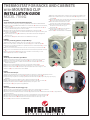
ThermosTaT for racks and cabineTs
wiTh mounTing clip
insTallaTion guide
MODEL 710442
INT-710442-QIG-ML1-0710-02-0
DEUTSCH
Thermostat für Racks und Schränke mit Befestigungsclip
1 Wählen Sie eine Stelle zur Anbringung aus. Durch die geringe Größe (60 x 33 x 43 mm) ist der Platzbedarf minimal.
2 Verbinden Sie die 2 beiliegenden Drähte mit den Klemmen 1 & 2 des Thermostats (A) und ziehen Sie die Schrauben fest,
um sie zu sichern (B).
3 Trennen Sie den Buchsenstecker des Lüfters (siehe Beispiel F1) vom Temperatursteuerungsmodul des Lüfters (C) und
verbinden Sie ihn mit dem beiliegenden Stecker-auf-Stecker-Adapter.
4 Verbinden Sie das andere Ende des Adapters mit einem der beiden Buchsenstecker des Thermostats (A).
5 Verbinden Sie den zweiten Buchsenstecker des Thermostats mit dem Temperatursteuerungsmodul (von dem Sie gerade
F1 [Lüfter 1] getrennt haben) (C).
6 Stellen Sie die Temperatursteuerung (D) auf den Wert ein, bei dem der Lüfter aktiviert werden soll. Möglich ist ein
Bereich von 0 - 60˚C.
7 Verwenden Sie den Clip (E), um den Thermostat an einer 35-mm-DIN-Schiene zu befestigen.
FRANÇAIS
Thermostat pour racks et bâtis ; clip de xation
1 Choisissez un placement pour le thermostat. Par son format compact (60 x 33 x 43 mm) il ne faut que peu d’espace.
2 Connectez les deux fils inclus aux terminaux 1 & 2 du thermostat (A) et resserrez les vis pour les fixer (B).
3 Déconnectez le connecteur femelle (cf. exemple F1) du module température du ventilateur (C) et connectez-le à
l’adaptateur mâle/mâle inclus.
4 Connectez l’autre bout mâle de l’adaptateur à un des deux connecteurs femelles du thermostat (A).
5 Connectez l’autre connecteur femelle du thermostat au module température (ou vous avez déconnecté F1) (C).
6 Ajustez le contrôle du thermostat (D) à la température à laquelle le ventilateur doit être activé. La plage est 0 - 60˚C.
7 Utilisez le clip (E) pour fixer le thermostat à un rail de 35 mm DIN.
ESPAÑOL
Termostato para Racks y gabinetes, con Clip de Montaje
1 Decida donde fijar el Termostato. El tamaño compacto (60 x 33 x 43 mm) requiere un espacio minimo.
2 Conecte los dos cables incluidos a las terminales 1 & 2 del termostato (A) y ajuste los tornillos para fijarlos (B).
3 Desconecte el conector hembra del ventilador (F1 en el ejemplo) del modulo de control de temperatura (C) y conectelo
al extensor incluido macho-macho.
4 Conecte el otro extremo macho de la extensión a uno de los dos conectores hem bra que va desde el termostato (A).
5 Conecte el otro conector hembra del termostato hasta el módulo de control de temperatura (que habia desconectado F1)
(C).
6 Ajuste el control del termostato (D) a la temperatura a la que el ventilador se encenderá. El rango es 0 - 60˚C.
7 Use el clip(E) para fijar el termostato a un riel DIN de 35 mm.
POLSKI
Termostat do szaf rackowych
1 Znajdź w szafie odpowiednie miejsce na montaż termostatu. Kompaktowe rozmiary (60 x 33 x 43 mm) nie wymagają dużej przestrzeni.
2 Podłącz dwa dołączone kable do złącz 1 i 2 termostatu (A) i przykręć śrubki, aby zabezpieczyć przewody (B).
3 Odłącz żeńskie złącze wentylatora (F1 w pokazanym przykładzie) z modułu kontroli temperatury ( C) i podłącz do dołączonego męsko-męskiego
przedłużacza.
4 Podłącz drugą męską końcówkę przedłużacza do jednego z dwóch żeńskich złącz termostatu (A).
5 Podłącz drugie żeńskie złącze termostatu do modułu kontroli temperatury (w miejsce, gdzie odłączone zostało F1) (C).
6 Gdy włączy się wentylator, ustaw termostat (D) na pożądaną temperaturę. Zakres wynosi 0 – 60˚C.
7 Za pomocą klipsów (E) przymocuj termostat do szyny DIN 35 mm.
ITALIANO
Termostato per Armadi e Rack, montaggio a clip
1 Decidere dove deve essere posizionato il termostato. Le dimensioni compatte (60 x 33 x 43 mm) richiedono poco spazio libero.
2 Collegare le due fili elettrici inclusi ai terminali 1 & 2 del termostato (A) e stringere le viti per fissarli (B).
3 Disconnettere il connettore femmina della ventola (F1 nell’esempio raffigurato) dal modulo di controllo della temperature della ventola (C) e collegarlo all’extender
maschio-maschio incluso.
4 Collegare l’altra parte terminale maschio dell’extender a uno dei due connettori femmina che provengono dal termostato (A).
5 Collegare l’altro connettore femmina dal termostato al modulo di controllo della temperatura (dove basta scollegare F1) (C).
6 Settare il controllo del termostato (D) alla temperature desiderata quando la ventola si accende. Il range è 0 - 60˚C.
7 Usare la clip (E) per attaccare il termostato a una barra DIN da 35 mm.
1 Decide where to place the thermostat. The compact size (60 x 33 x 43 mm) requires minimal clearance.
2 Connect the two included lead wires to the 1 & 2 thermostat terminals (A) and tighten the screws to
secure them (B).
3 Disconnect the female fan connector (F1 in the example shown) from the fan’s temperature control module
(C) and connect it to the included male-to-male extender.
4 Connect the other male end of the extender to one of the
two female connectors leading from the thermostat (A).
5 Connect the other female connector from the thermostat to
the temperature control module (where you just
disconnected F1) (C).
6 Set the thermostat control (D) to the desired temperature
when the fan will turn on. The range is 0 - 60˚C.
7 Use the clip (E) to attach the thermostat to a 35 mm DIN rail.
b
a
d
e
c
La page charge ...
-
 1
1
-
 2
2


Intellinet 710442 Manuel utilisateur
- Catégorie
- Accessoires de rack
- Taper
- Manuel utilisateur
- Ce manuel convient également à
dans d''autres langues
- English: Intellinet 710442 User manual
- español: Intellinet 710442 Manual de usuario
- polski: Intellinet 710442 Instrukcja obsługi
Documents connexes
-
Intellinet 19" Rackmount Digital Thermostat Manuel utilisateur
-
-
-
IC Intracom 506601 Manuel utilisateur
-
-
-
-
-
Intellinet 502900 Manuel utilisateur