
FOR YOUR SAFETY
If you smell gas:
1. Open windows.
2. Don’t touch electrical switches.
3. Extinguish any open fl ame.
4. Immediately call your gas supplier.
POUR VOTRE SÉCURITÉ
Si vous sentez une odeur de gaz:
1. Ouvrez les fenêtres.
2. Ne touchez à aucun interrupteur.
3. Éteignez toute fl amme nue.
4. Avertissez immédiatement votre
fournisseur de gaz.
FOR YOUR SAFETY
Do not store or use gasoline or other
fl ammable vapors and liquids in the
vicinity of this or any other appliance.
POUR VOTRE SÉCURITÉ
Ne pas entreposer ni utiliser de l’essence
ni d’autres vapeurs ou liquides infl amma-
bles à proximité de cet appareil ou de tout
autre appareil.
Improper installation, adjustment, altera-
tion, service or maintenance can cause
injury or property damage. Refer to this
manual. For assistance or additional infor-
mation consult a qualifi ed installer, serv-
ice agency or the gas supplier.
Une installation, un réglage, une modifi -
cation, une réparation ou un entretien non
conforme aux normes peut entraîner des
blessures ou des dommages matériels.
Lisez attentivement le mode d’emploi
fourni avec l’appareil. Pour obtenir de
l’aide ou des renseignements supplémen-
taires, consultez un installateur ou un
service d’entretien qualifi é ou le fournis-
seur de gaz.
NEA1402
NDA1402
autodefrost
INSTALLATION
MANUAL
USA
Corporate Offi ce
CANADA
Service Offi ce 2320 Industrial Parkway Elkhart, IN 46515 Dometic Corporation
Dometic Corporation
46 Zatonski, Unit 3
2320 Industrial Pkwy. Brantford, ON, N3T 5L8
Elkhart, IN 46516
For Service Center Assistance
CANADA
Phone: 574-294-2511 Call: 800-544-4881 Phone: 519-720-9578
®
®
MO-M 0608
825125900
©Dometic Corporation
LaGrange, IN 46761
WARNING
!
!
AVERTISSEMENT

This product is manufactured under license of
U.S. Patent Number 6.019,447
Patents pending
U.S. 10/619,675
U.S. 10/620,177
U.S. 10/758,174
U.S. 10/758,175
U.S. 10/760,564
U.S. 10/760,565

– 3 –
C
E
RTIFICATION AND CODE REQUIREMENTS
______
4
VENTILATION REQUIREMENTS
__________________
4
General information
. . . . . . . . . . . . . . . . . . . . . . . . . . . . . . . . . .
4
Venti
lation heights
. . . . . . . . . . . . . . . . . . . . . . . . . . . . . . . . . . .
4
INSTALLATION INSTRUCTIONS
__________________
5
Installing the refrigerator
. . . . . . . . . . . . . . . . . . . . . . . . . . . . . .
5
Securing the refrigerator
. . . . . . . . . . . . . . . . . . . . . . . . . . . . . .
5
Installing the drain water hose
. . . . . . . . . . . . . . . . . . . . . . . . . .
6
GAS/ELECTRICAL CONNECTION
________________
6
Gas connection (NDA1402)
. . . . . . . . . . . . . . . . . . . . . . . . . . . .
6
Electrical connection
. . . . . . . . . . . . . . . . . . . . . . . . . . . . . . . . .
7
REFRIGERATOR REMOVAL
_____________________
7
MOUNTING THE DOOR PANELS
_________________
8
APPENDIX A - TECHNICAL DATA
________________
APPENDIX A - TECHNICAL DATA ________________APPENDIX A - TECHNICAL DATA
1
2
APPENDIX B -
REARVIEW EQUIPMENT
__________
1
3
APPENDIX C - WIRING DIAGRAMS
______________
1
6
INTRODUCTION
This manual describes how to install NEA1402 (all-electric operation) and NDA1402 (2-way operation). These models can be
equipped with an ice maker, an ice dispenser or ice & water dispensers.
The information in this manual is intended for qualifi ed technicians with knowledge and experience of absorption refrigerators and
LP gas systems. For operating instructions, please refer to the User manual for the appliance in question.
Read this manual before installing the refrigerator. Comply with installation specifi cations and dimensions. Follow the instructions
to ensure that the refrigerator is installed safely and that it runs effi ciently. Be aware of possible safety hazards when seeing alert
symbols on the refrigerator as well as in this manual.
CONTENTS
SYMBOLS
The following symbols are used throughout the manual:
Indicates a potentially hazardous situation, which, if not avoided, could result
in death or serious injury.
Indicates a potentially hazardous situation, which, if not avoided, may result in
minor or moderate injury.
Used without the safety alert symbol indicates, a potentially hazardous situation which, if not avoided
may result in property damage.
Information
Step-by-step instructions
CAUTION
!
WARNING
!
CAUTION

– 4 –
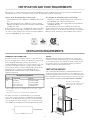
NDA1402
When installing the refrigerator, make sure to separate the
combustion system from the living space of the mobile home
or recreational vehicle. An opening toward the outside at fl oor
level in the refrigerator compartment must be provided for
ventilation of heavier-than-air fuel gases.
VENTILATION HEIGHTS
It is essential that all maximum or minimum dimensions are
strictly maintained as the performance of the refrigerator is de-
pendent on adequate fl ow of air over the rear of the refrigerator.
For an installation with roof vent and lower side vent, the mini-
mum ventilation height should be
69-1/8 inches (1756 mm)
.
VENTILATION REQUIREMENTS
GENERAL INFORMATION
Provide necessary air circulation over the cooling unit. Open-
ings for air supply or for venting of combustion products shall
have a minimum dimension of not less than 1/4 inch.
Certifi ed installations require one roof vent and one lower side
vent. Proper installation requires one lower fresh air intake
and one upper exhaust vent. The ventilation kits shown in this
manual have been certifi ed for use with NEA1402 and
NDA1402. The ventilation kits must be installed and used
without modifi cation.
The lower vent of the recommended kits is provided with
proper size openings. The fl ow of combustion and ventilating
air must not be obstructed. The lower side vent is fi tted with
a panel, which provides an adequate access opening for ready
serviceability of the burner and control manifold of the refrig-
erator. This should be centered on the back of the refrigerator.
LOWER VENT CUTOUT
13-5/8”
28-5/
8”
Lower vent cutout
Ventilation
heigh
t
Condenser
The upper vent should be
centered over the condenser coil
at the back of the refrigerator.
Certifi ed vent system kits
Kit no.
Components
Part no.
5A
Roof Base
Roof Cover
Lower Side Vent
Power Vent Asm.
3103633.XXX*
3103634.XXX*
3109349.XXX*
3108705.744**
*
Fill in “XXX” with color code numbers. For color codes, contact
your supplier.
** Alternate instructions forwarded with the Ventilator Kit.
The appliance is certifi ed under the latest edition of ANSI Z21.19•CSA 1.4 Refrigerators using gas fuel. The installation must
conform with local codes, or in absence of local codes, the following standards as applicable.
In the U.S. the installation must conform with:
National Fuel Gas Code, ANSI Z223.1/NFPA 54 (latest edi-
tion).
Recreational Vehicles Code, ANSI A119.2 (latest edition)
Manufactured Home Construction and Safety Standard, Title
24 CFR, Part 3280.
If an external electrical source is utilized, the refrigerator, when
installed, must be electrically grounded in accordance with lo-
cal codes or, in the absence of local codes, the National Electri-
cal Code, ANSI/NFPA 70 - (latest edition).
•
•
•
In CANADA, the installation must conform with:
Natural Gas and Propane Installation Code, CSA B149.1
CSA Z240 RV Series, Recreational Vehicles.
Current CSA Z240.4, Gas-equipped Recreational Vehicles
and Mobile Housing.
If an external electrical source is utilized, the refrigerator,
when installed, must be electrically grounded in accordance
with local codes or, in the absence of local codes, the Canadian
Electrical Code, CSA C22.1, Parts I and II - (latest edition).
•
•
•
CERTIFICATION AND CODE REQUIREMENTS

– 5 –
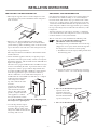
INSTALLATION INSTRUCTIONS
INSTALLING THE REFRIGERATOR
The transport support at the rear of the refrigerator can be
removed if necessary for the installation of the refrigerator
in the enclosure.
Please use care when installing the refrigerator! This
refrigerator is equipped with the latest vacuum insulated
panel technology. These insulating panels are located on the
top, back, bottom, sides and doors of the refrigerator. If the
surface is punctured, loss of insulation will occur, resulting
in poor refrigerator performance.
The refrigerator must be installed in a substantial enclosure
and must be level.
Do not install the appliance directly on carpeting. Carpet-
ing must be removed or protected by a metal or wood panel
beneath the appliance, which extends at least full width and
depth of the appliance.
Clearances: In a proper installation there should be zero (0”)
clearance surrounding the sides, top, bottom and rear of the
refrigerator to achieve proper air fl ow. All potential dead
air pockets should be blocked or baffl ed to ensure that heat
won’t be trapped in these spaces and reduce effi ciency.
All areas within the recess in which the refrigerator is
installed must be sealed. Make sure that there is a complete
seal between the front frame
of the refrigerator and the
top, sides and bottom of the
enclosure.
A length of sealing strip is
applied to the rear surface
of the front frame for this
purpose. The sealing should
provide a complete isolation
of the appliance’s combus-
tion system from the vehicle
interior.
Be careful not to damage the sealing strip when
the refrigerator is put in place!
A wood strip must be in place
across the upper opening of the
enclosure. The top frame of the
refrigerator will be anchored to the
wood strip with screws.
•
•
•
•
•
•
•
Wood strip
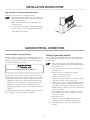
SECURING THE REFRIGERATOR
It is important to follow the sequence in securing refrigerator
in enclosure since failure in doing so can cause leakage be-
tween the frame and cabinet. Any space between the counter,
storage area or ceiling and top of the refrigerator greater den
1-1/2 inches should be blocked. The heat produced at the rear
of the refrigerator will become trapped in this space, making
the top of the refrigerator hot and reduce the effi ciency of the
refrigerator.
After the refrigerator is put in place (ensuring a combustion
seal at the front frame), the refrigerator is to be secured in the
enclosure with six screws (not included).
The six screws have to be installed in the following order:
Two screws installed through the front base.
(Installation of the lower front strip.)
The refrigerator is provided with a lower front strip
(shipped as a loose part). Attach the front strip after
the refrigerator is set into the cutout opening.
Install the lower front strip by sliding it under the
bottom hinge plates.
Secure the refrigerator and the lower front strip
with two screws - one screw through each hinge.
Two screws installed in he top frame.
Open the doors and
fasten the refrigerator
with two screws through
the holes underneath the
top decoration panel.
Two screws installed in the rear base.
1.
a)
b)
2.
3.

– 6 –
GAS CONNECTION (NDA1402)
Hook up to the gas supply line is accomplished at the manual
gas valve, which is furnished with a 3/8” SAE (UNF 5/8” -18)
male fl are connection. All completed connections should be
checked for leaks with soapy water.
Do not use a fl ame to check for gas leaks!
The gas supply system must incorporate a pressure regulator
to maintain a supply pressure of not more than 11 inches water
column. When testing the gas supply system at test pressures:
> 1/2 psi
- the refrigerator and its individual shutoff valve
must be disconnected from the gas supply piping system.
≤
1/2 psi
- the appliance must be isolated from the gas
supply piping system by closing its individual manual shut-
off valve.
For detailed instructions on the installation and connection to
the gas supply, contact your dealer or distributor.
•
•
INSTALLING THE DRAIN WATER HOSE
To install the drain water hose, follow these steps:
Drill a hole through fl ooring. It is essential that it is
drilled in the cut out opening of the base plate at the
rear of the refrigerator.
Make sure that the hose does not kink when run
through the fl oor.
Seal around the hose that goes through the drilled
hole. If a longer hose than supplied is required, the
installer needs to supply one in order for the water to
drain outside of the vehicle.
1.
2.
3.
Testing LP gas safety shut off
The gas safety shut off must be tested after the refrigerator is
connected to LP gas supply. To test the gas safety shut off, fol-
low these steps:
Turn on the refrigerator and switch to GAS mode.
Check that the GAS indicator dot is illuminated and
the gas fl ame is lit.
Close the manual gas shut off valve at the back of
the refrigerator.
Wait for approx. 6-7 minutes. The message
“ch LP” is displayed (fl ashing).
Remove the protection cover.
Open the manual gas shut off valve. (Do not change
any button positions on the control panel.)
Apply a non corrosive commercial bubble solution
to the burner jet orifi ce. No bubbles should appear at
the opening of the burner jet orifi ce. The presence of
bubbles indicates a defective gas safety shut off, and
service is required.
If no bubbles were present at the burner jet orifi ce,
rinse it with fresh water. Be careful not to damage
the burner jet orifi ce.
Put back the cover.
Switch the refrigerator OFF and back ON again.
Normal operation of the burner should return.
Allow the burner to operate for a minimum of 5
minutes
1.
2.
3.
4.
5.
6.
7.
8.
9.
10.
Hole for drain
water
hose
INSTALLATION INSTRUCTIONS
GAS/ELECTRICAL CONNECTION
WARNING
!

– 7 –
ELECTRICAL CONNECTION
120 V AC connection
The refrigerator is equipped with a three-prong (grounding)
plug for your protection against shock hazards and should be
plugged directly into a properly grounded three prong recep-
tacle. DO NOT cut or remove the grounding prong from this
plug!
The free length of the cord is 2 feet and it is recommended that
the receptacle is located to the right side of the refrigerator
(viewed from the rear).
The receptacle should be 3” (from the
bottom of the plastic receptacle) above
the refrigerator mounting fl oor. This al-
lows easy access through the vent door.
The cord should be routed to avoid direct
contact with components that could
damage the cord insulation.
120 Volt AC
receptacl
e
3’’
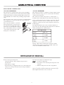
GAS/ELECTRICAL CONNECTION
12 V DC connection
The refrigerator requires a continuous 12 V DC supply to main-
tain the automatic energy selector system and the auto defrost
control system to function.
The connection is made to the positive (+) and negative (-)
terminals of the terminal block on the back of the refrigerator.
Correct polarity must be observed when connecting to the DC
supply. Do not use the chassis or vehicle frame as one of the
conductors. Connect two wires at the refrigerator and route to
the DC supply.
It is important that the wires to the 12 V DC terminal is of
proper wire size. The following table displays the recommend-
ed size and length of the conductor wires.
Wire length & size
Length
Min. size
< 33 ft
< 10 m
12 AWG
33 - 66 ft
10 - 20 m
10 AWG
> 66 ft
> 20 m
8 AWG
Example:
If the distance between the refrigerator and the
12V DC supply is 20 ft., the total wire length is 40 ft. and
a wire size of 10 AWG should be used.
Before removing the refrigerator:
Verify that the AC voltage and DC voltage leads are
disconnected.
Shut off the gas supply.
Disconnect the gas supply line at the rear of the refrigerator.
Always use a back up wrench when loosening and tighten-
ing connections.
•
•
•
REFRIGERATOR REMOVAL
To remove the refrigerator, follow these steps:
Cap the gas supply line.
Loosen the screws anchoring the refrigerator to the
enclosure.
Slide the refrigerator out of the compartment.
When replacing the refrigerator make sure that the sealing
strips are properly positioned. Check all connections for gas
leaks. Replacement is the reverse of removal.
1.
2.
3.

– 8 –
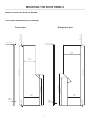
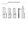
MODELS EQUIPPED WITH ICE MAKER
MOUNTING THE DOOR PANELS
Freezer door Refrigerator door
DOOR PANEL DIMENSIONS (INCHES AND MM)

– 9 –
FITTING THE DOOR PANELS
MOUNTING THE DOOR PANELS

– 10 –
Freezer door Refrigerator door
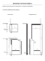
MODELS EQUIPPED WITH ICE DISPENSER / ICE & WATER DISPENSERS
MOUNTING THE DOOR PANELS
DOOR PANEL DIMENSIONS (INCHES AND MM)

– 11 –
Freezer door
Refrigerator
door
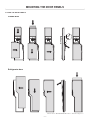
MOUNTING THE DOOR PANELS
Model shown: NEA1402/NDA1402 with ice and water dispensers.
FITTING THE DOOR PANELS

– 12 –
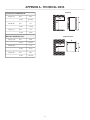
OVERALL DIMENSIONS
Height (A)
mm
1632
inches
64-17/64
Width (B)
mm
855
inches
33-11/16
Depth (C)
mm
752
inches
29-5/8
RECESS DIMENSIONS
Height (H)
mm
1605
inches
63-3/16
Width (W)
mm
832
inches
32-3/4
Depth (D)
mm
662
inches
26-1/16
APPENDIX A - TECHNICAL DATA
D
W
C
B
View from above
D
H A
Side view

– 13 –
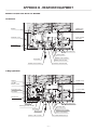
APPENDIX B - REARVIEW EQUIPMENT
MODELS EQUIPPED WITH ICE MAKER
2-way operation
All-electric
Thermostat
12V DC
12V DC
Heaters
Protection
cover
Thermofuse
Water hose icemaker
Hea
ting cable
12
Volt DC Terminal block
Water solenoid valve
Drain
water hose
Power
module
and
fuses
Flexible
cord
Re
frigerator
Flexible cord Ice maker

– 14 –
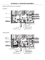
APPENDIX B - REARVIEW EQUIPMENT
MODELS EQUIPPED WITH ICE DISPENSER
All-electric
2-way operation
Heaters
12V
DC
Burner
control
Protection
cover
Flue
baffle
Thermofuse
Burner
jet
Manual
gas shut off valve
Inlet fitting
Thermost
at
Flexible
cord
Ice
maker, Ice dispenser
12V DC
12V DC
Water solenoid valve
Water hose Ice maker
Heating cabel
Drain
water hose
12
Volt DC Terminal block
Flexible
cord
Re
frigerator
Ice
dispenser
power
switch
Power
module
and
fuses

– 15 –
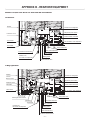
APPENDIX B - REARVIEW EQUIPMENT
All-electric
2-way operation
MODELS EQUIPPED WITH ICE AND WATER DISPENSER
Heaters
Protection
cover
Thermofuse
Thermos
tat
Drain
water hose
12 Volt DC Terminal block
Hose, icemaker
Hose, water dispenser
Heating
cable
Water solenoid valve
Flexible
cord
Ice
maker, Ice dispenser
Flexible
cord refrigerator
Dispenser power switch
Power
module
and
fuses
90° connection, water dispenser
Heaters
12V DC
Burner
control
Protection
cover
Flue
baffle
Thermofuse
Burner
jet
Manual
gas shut off valve
Inlet fitting
Thermost
at
Flexible
cord
Ice
maker, Ice dispenser
12V DC
12V DC
12 Volt DC Terminal block
Drain water hose
Hose, icemaker
Hose, water dispenser
Heating cable
Water solenoid valve
Flexible cord refrigerator
Dispenser power
switch
Power
module
and
fuses
90° connection, water dispenser

– 16 –
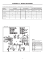
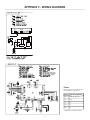
APPENDIX C - WIRING DIAGRAMS
Fuses
Fuses (from left to right) protect
the following components.
Fuse
Type of component
3A
A, B, C, E, G, H, P, R
7.5A
S, T
3A
W*
7.5A
X
5A
Z
*
Optional ice maker heat-kit
WIRING
DIAGRAM
ICE MAKER
ICE DISPENSER
ICE & WATER DISPENSERS
All-electric
2-way
All-electric
2-way
All-electric
2-way
385 06 98
X
X
X
385 06 99 (2)
X
X
385 07 07
X
X
X
385 08 97 (3)
X
X
385 11 12
X
X
385 06 98
The following table displays the different types of models and their corresponding wiring diagrams.

– 17 –
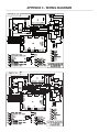
APPENDIX C - WIRING DIAGRAMS
385 06 99 |2|
385 07 07
Fuses
Fuses (from left to right) protect
the following components.
Fuse
Type of component
3A
A, B, D, F, G, N
7.5A
O, P
3A
T*
7.5A
U
5A
Z
*
Optional ice maker heat-kit

– 18 –
385 08 97 |3|
APPENDIX C - WIRING DIAGRAMS
385 11 12


TO THE INSTALLER
PLEASE AFFIX THESE INSTRUCTIONS
TO THE REFRIGERATOR
—
TO THE CONSUMER
PLEASE RETAIN THESE INSTRUCTIONS
FOR FUTURE REFERENCE
-
 1
1
-
 2
2
-
 3
3
-
 4
4
-
 5
5
-
 6
6
-
 7
7
-
 8
8
-
 9
9
-
 10
10
-
 11
11
-
 12
12
-
 13
13
-
 14
14
-
 15
15
-
 16
16
-
 17
17
-
 18
18
-
 19
19
-
 20
20


Dometic NDA1402 Manuel utilisateur
- Taper
- Manuel utilisateur
- Ce manuel convient également à
dans d''autres langues
- English: Dometic NDA1402 User manual
Documents connexes
-
Dometic NDA1402 Manuel utilisateur
-
Dometic RM1350 Manuel utilisateur
-
-
-
-
-