Pepperl+Fuchs VT18-8-400-M-LAS/40a/118/128 Mode d'emploi
- Taper
- Mode d'emploi

alle Maße in mm
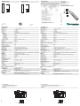
Dimensions
Abmessungen
Technische Daten
Technical data
Elektrischer Anschluss
Electrical connection
Adressen/Addresses
Sicherheitshinweise:
•Vor der Inbetriebnahme Betriebsanleitung lesen
• Anschluss, Montage und Einstellung nur durch Fachpersonal
• Kein Sicherheitsbauteil gemäß EU-Maschinenrichtlinie
Security Instructions:
• Read the operating instructions before attempting commissioning
• Installation, connection and adjustments should only be undertaken by specialist personnel
• Not a safety component in accordance with the EU Machinery Directive
all dimensions in mm
www.pepperl-fuchs.com
Pepperl+Fuchs GmbH
68301 Mannheim · Germany
Tel. +49 621 776-4411
Fax +49 621 776-27-4411
E-mail: fa-inf[email protected]
Worldwide Headquarters
Pepperl+Fuchs GmbH · Mannheim · Germany
E-mail: fa-inf[email protected]
USA Headquarters
Pepperl+Fuchs Inc. · Twinsburg · USA
E-mail: fa-inf[email protected]
Asia Pacific Headquarters
Pepperl+Fuchs Pte Ltd · Singapore
E-mail: fa-inf[email protected]
Company Registration No. 199003130E
TastweiteneinstellerHell-/Dunkel-Umschalter
Anzeigen/
Bedienelemente
LED gelb LED grün
Detail "A"
Detail "A"
M18 x 1
4
24
11.2
7.8
2
43.8
44.6
47.1
53.9
65
78
SENS.
DL
Reflexionslichttaster
mit Gerätestecker M12 x 1, 4-polig
Diffuse mode sensor
with 4-pin, M12 x 1 connector
VT18-8-400-M-LAS/40a/118/128
Allgemeine Daten
Tastbereich 0 ... 400 mm , einstellbar
Tastbereich min. 0 ... 25 mm
Tastbereich max. 0 ... 400 mm
Lichtsender Laserdiode
Lichtart rot, Wechsellicht
Laserkenndaten
Hinweis LASERLICHT , NICHT IN DEN STRAHL BLICKEN
Laserklasse 1
Wellenlänge 655 nm
Strahldivergenz 31,5 mrad
Impulsdauer 4 s
Wiederholrate 11,91 kHz
max. Puls Energie 4,95 nJ
Lichtfleckdurchmesser ca. 0,5 mm im Abstand von 120 mm
Lichtaustritt frontal
Fremdlichtgrenze 30000 Lux
Hysterese H < 15 %
Kenndaten funktionale Sicherheit
MTTFd 700 a
Gebrauchsdauer (TM) 20 a
Diagnosedeckungsgrad (DC) 0 %
Anzeigen/Bedienelemente
Betriebsanzeige LED grün, blinkend im Kurzschlussfall
Funktionsanzeige LED gelb, leuchtet bei belichtetem Empfänger
Bedienelemente Tastweiteneinsteller, Hell-/Dunkelumschalter
Elektrische Daten
Betriebsspannung UB10 ... 30 V DC , class 2
Leerlaufstrom I0< 25 mA
Schutzklasse II , Bemessungsspannung 50 V AC bei Verschmutzungsgrad 1-2 nach IEC 60664-1
Ausgang
Schaltungsart hell-/dunkelschaltend, umschaltbar
Signalausgang Gegentaktausgang, kurzschlussfest, verpolgeschützt
Schaltspannung 30 V DC
Schaltstrom max. 200 mA
Schaltfrequenz f 500 Hz
Ansprechzeit 1 ms
Umgebungsbedingungen
Umgebungstemperatur -25 ... 55 °C (-13 ... 131 °F)
Lagertemperatur -30 ... 70 °C (-22 ... 158 °F)
Mechanische Daten
Schutzart IP67
Anschluss Gerätestecker M12 x 1, 4-polig
Material
Gehäuse Messing, vernickelt
Lichtaustritt PMMA
Masse 60 g
Normen- und Richtlinienkonformität
Richtlinienkonformität EMV-Richtlinie 2004/108/EG
Normenkonformität
Produktnorm EN 60947-5-2:2007
IEC 60947-5-2:2007
Laserklasse IEC 60825-1:2007 Complies with 21 CFR 1040.10 and 1040.11 except for deviations
pursuant to Laser Notice No. 50, dated June 24, 2007
Zulassungen und Zertifikate
CE-Konformität ja
UL-Zulassung cULus Listed, Type 1 enclosure
CCC-Zulassung Produkte, deren max. Betriebsspannung 36 V ist, sind nicht zulassungspflichtig und
daher nicht mit einer CCC-Kennzeichnung versehen.
Light/dark switch
Indicating/
Operating means
LED yellow LED green
Detail "A"
Detail "A"
Sensing range adjuster
M18 x 1
4
24
11.2
7.8
2
43.8
44.6
47.1
53.9
65
78
SENS.
DL
07/31/2018
Date:
Option:
2
1
3
4
+UB
n. c.
Q
0 V
/128
1
3
4
2
General specifications
Detection range 0 ... 400 mm , adjustable
Detection range min. 0 ... 25 mm
Detection range max. 0 ... 400 mm
Light source laser diode
Light type modulated visible red light
Laser nominal ratings
Note LASER LIGHT , DO NOT STARE INTO BEAM
Laser class 1
Wave length 655 nm
Beam divergence 31.5 mrad
Pulse length 4 s
Repetition rate 11.91 kHz
max. pulse energy 4.95 nJ
Diameter of the light spot approx. 0.5 mm at a distance of 120 mm
Optical face frontal
Ambient light limit 30000 Lux
Hysteresis H < 15 %
Functional safety related parameters
MTTFd 700 a
Mission Time (TM) 20 a
Diagnostic Coverage (DC) 0 %
Indicators/operating means
Operation indicator LED green, flashes in case of short-circuit
Function indicator LED yellow, lights up with receiver lit
Control elements Sensing range adjuster, light-on/dark-on changeover switch
Electrical specifications
Operating voltage UB10 ... 30 V DC , class 2
No-load supply current I0< 25 mA
Protection class II , rated voltage 50 V AC with pollution degree 1-2 according to IEC 60664-1
Output
Switching type light/dark on, switchable
Signal output Push-pull output, short-circuit protected, reverse polarity protected
Switching voltage 30 V DC
Switching current max. 200 mA
Switching frequency f 500 Hz
Response time 1 ms
Ambient conditions
Ambient temperature -25 ... 55 °C (-13 ... 131 °F)
Storage temperature -30 ... 70 °C (-22 ... 158 °F)
Mechanical specifications
Degree of protection IP67
Connection 4-pin, M12 x 1 connector
Material
Housing brass, nickel-plated
Optical face PMMA
Mass 60 g
Compliance with standards and direc-
tives
Directive conformity EMC Directive 2004/108/EC
Standard conformity
Product standard EN 60947-5-2:2007
IEC 60947-5-2:2007
Laser class IEC 60825-1:2007 Complies with 21 CFR 1040.10 and 1040.11 except for deviations
pursuant to Laser Notice No. 50, dated June 24, 2007
Approvals and certificates
CE conformity yes
UL approval cULus Listed, Type 1 enclosure
CCC approval CCC approval / marking not required for products rated 36 V
= Hellschaltung
= Dunkelschaltung
= Light on
= Dark on
Option:
2
1
3
4
+UB
n. c.
Q
0 V
/128
DIN A3 -> A7
Part. 801135 45-0567H
Doc.

• Die Bestrahlung kann zu Irritationen gerade bei dunkler Umgebung führen. Nicht auf Menschen richten!
• Wartung und Reparaturen nur von autorisiertem Servicepersonal durchführen lassen!
• Das Gerät ist so anzubringen, dass die Warnhinweise deutlich sichtbar und lesbar sind.
• Der Warnhinweis liegt dem Gerät bei und ist in unmittelbarer Nähe zum Gerät gut sichtbar anzubringen.
• Vorsicht: Wenn andere als die hier angegebenen Bedienungs- oder Justiereinrichtungen benutzt oder andere Verfahrenswei-
sen ausgeführt werden, kann dies zu gefährlicher Strahlungseinwirkung führen.
• The irradiation can lead to irritation especially in a dark environment. Do not point at people!
• Maintenance and repairs should only be carried out by authorized service personnel!
• Attach the device so that the warning is clearly visible and readable.
• The warning accompanies the device and should be attached in immediate proximity to the device.
• Caution – Use of controls or adjustments or performance of procedures other than those specified herein may result in hazar-
dous radiation exposure.
• L’irradiation peut entraîner des irritations dans un environnement sombre. Ne pas orienter vers les personnes !
• L’entretien et les réparations doivent être réalisés exclusivement par le personnel de service autorisé !
• L’appareil doit être installé de manière à ce que les mises en garde soient clairement visibles et lisibles.
• Les instructions de mise en garde sont jointes à l’appareil et doivent être installées à proximité directe de l'appareil de manière
visible.
• Attention : Si d’autres dispositifs de commande ou de réglage sont utilisés que ceux indiqués ici, ou si d’autres procédures
sont exécutées, cela peut entraîner un effet préjudiciable du rayonnement.
LASERLICHT
LASER LIGHT
LASER KLASSE 1
CLASS 1 LASER PRODUCT
LASER Warnhinweise nach IEC 60825-1:2007, 21CFR 1040.10 und 1040.11 (except for deviations pursuant to Laser
Notice No. 50, dated 6-24-07) konnten nicht am Gerät befestigt werden. Die Warnhinweise sind selbstklebend und lie-
gen der Verpackung bei.
LASER hazard warning labels required by IEC 60825-1:2007, 21CFR 1040.10 and 1040.11 (except for deviations pur-
suant to Laser Notice No. 50, dated 6-24-07) could not be affixed to the product, but are supplied with the product as
self-adhesive labels in the product packaging.
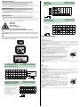
Montagehinweise
Bestimmungsgemäße Verwendung
Ein Reflexionslichttaster enthält Sender und Empfänger in einem Gehäuse. Das Licht des Senders wird vom erfassten Objekt
reflektiert und zum Empfänger zurückgestrahlt und dort ausgewertet. Die Tastweiten sind von der Objektfarbe abhängig. Bei
dunklen oder sehr kleinen Objekten reduziert sich die Tastweite.
Montagehinweise:
Die Sensoren können aufgrund ihrer M18 x 1 Gewindebauform und unter Verwendung der zwei mitgelieferten Muttern (SW 24
mm / max. Drehmoment 1,5 Nm) durch eine einfache Bohrung mit Ø 18 mm oder mit einem Haltewinkel (nicht im Lieferumfang)
montiert werden.
Beachten Sie bei der Montage die Lage und Sichtbarkeit des Bedienfeldes bzw. der LED-Anzeigen.
Nach Anlegen der Betriebsspannung signalisiert die LED grün Betriebsbereitschaft.
Bei kurzgeschlossenem Ausgang (Fehler in der Verdrahtung) blinkt die LED grün.
Einstellung:
Stellen Sie den Empfindlichkeitsregler (gegen den Uhrzeigersinn) auf Minimum.
Platzieren Sie das Tastgut innerhalb des Tastbereiches und drehen Sie den Empfindlich-
keitsregler im Uhrzeigersinn bis die Anzeige-LED gelb aufleuchtet. Merken Sie sich diese
Stellung des Empfindlichkeitsreglers als Position A.
Entfernen Sie das Objekt aus dem Tastbereich des Sensors. Erhöhen Sie die Sensoremp-
findlichkeit langsam weiter bis die gelbe LED erneut aufleuchtet. Merken Sie sich diese Stel-
lung des Empfindlichkeitsreglers als Position B.
Hinweis:
Wenn kein Hintergrundobjekt vorhanden ist, so wird die gelbe LED auch in Stellung MAX.
nicht aufleuchten. Stellen Sie in diesem Fall sicher, dass auch im normalen Betrieb kein Hin-
tergrundobjekt in das Tastfeld des Sensors gelangen kann (abgestellte Palette o. ä.).
Kann dies nicht ausgeschlossen werden, so platzieren Sie an entsprechender Stelle ein
Hintergrundobjekt, welches nach erfolgter Einstellung wieder entfernt wird.
Zur optimalen Empfindlichkeitseinstellung drehen Sie nun den Einsteller in die Mitte zwi-
schen den beiden Positionen A und B.
Reinigung:
Wir empfehlen in regelmäßigen Abständen den Lichtaustritt zu reinigen und Verschraubungen, sowie die Steckverbindungen zu
überprüfen.
Mounting instructions
Conventional use:
The reflex light scanner contains the emitter and receiver in a single housing. The light from transmitter is beamed back from the
recorded object is evaluated by the receiver.
The detection range depend on the object colour. With dark or very small objects the detection range reduces.
Mounting the sensor:
On account of the M18 x 1 thread, the two nuts (width across 24 mm / maximum torque 1.5 Nm) supplied along with the unit can
be used to mount the sensors by means of a single borehole of 18 mm in diameter or a holding angle (not included in the scope
of delivery).
Please observe the position and visibility of the operating panel and/or the LEDs when mounting.
After application of the operation voltage the LED signals green - ready for operation.
If the output is short-circuited (wiring fault) the LED flashes green.
Adjustment instructions:
Set sensitivity adjuster (counterclockwise) to minimum position.
Place the object to be detected in the sensing range and turn the sensitivity adjuster clockwi-
se until the yellow indication LED lights up. This setting indicates the position A of the sensi-
tivity adjuster.
Remove the object. Increase the sensitivity slowly until the yellow LED lights up again. This
setting indicates the position B of the sensitivity adjuster.
Note:
In case of no background object, the LED won't light up, even in MAX. setting. In that case
take car, that in normal operation no temporal background object can appear to the sensing
range (e. g. parked pallets). If this can not be excluded, place (only for adjustment matter) an
object at the appropriate location. Then repeat this adjustment step. After finishing the adjus-
tment this temporal object should be removed.
For optimal setting, now turn the sensitivity adjuster to the middle position between the posi-
tions A and B.
Lustration:
We recommend that you clean the optical interfaces and check the plug- and screw connections at regular intervals.
Laserhinweis Laserklasse 1
Laser notice laser class 1
Consigne laser classe 1
LASER Warnhinweise / LASER hazard warning labels
Funktionsreserve,
Stability control, Réserve de fonctionnement,
Reserva de función, Funzione riserva
VT18-8-400-LAS
x
60
50
40
30
20
10
0
10050 150 200 250 450
0300 350 400
Relative Empfangslichtstärke
Intensité relative de la lumière reçue
Intensità relativa luce in ricezione
Relative received light strength
Potencia relativa de recepción lumínica
X [mm]
90 % weiß/white/
blanc/blanco/bianco
18 % grau/grey/
gris/gris/grigio
6 % schwarz/black/
noir/negro/nero
X [mm]
Y [mm] VT18-8-400-LAS
x
y
0 10050 200150 300250 350 400 450
-6
-4
-2
0
2
4
6
Charakteristische Ansprechkurve
Courbe de response caractéristique
Curve di risposta caratteristica
Characteristic response curve
Curva de respuesta característica
Möglicher Abstand (Versatz) zwischen
optischer Achse und Referenzobjekt.
Permissible distance (offset) between
optical axis and reference target.
Ecart possible entre l'axe optique et la
cible de référence.
Desplazamiento entre el eje óptico y
objeto de referencia.
Distanza possibile (sfalsato) tra l'asse
ottico e l'ogetto di riferimento.
VT18-8-400-LAS
6 %
18 %
90 %
x
X [mm]
0 50 100 150 200 250 300 350 400 450
Tastbereiche
Detection ranges
Distanzas utiles
Rangos de detección
Domaines de detection
Reflexion/Reflection
Réflexion/Reflexión
Riflesso
*)
12
10
8
6
4
2
00 50 100 150 200 250 300 350 400 450
X
*)
X [mm]
[mm]
Strahldivergenz
Emission divergence
Divergence du faisceau
Divergencia del haz
Divergenza del raggio
Lichtfleckgröße / Light spot dimensions / Dimensions du tache lumineuse /
Dimension del punto de luz / Dimensioni del punto luminoso
Lichtfleck
Light spot
Tache lumineuse
Imagen del punto de luz
Punto luminoso
Beschreibung/Desciption
Empfindlichkeits-
einsteller
Hell-/Dunkel-
Umschalter
LED gelb
LED grün
Position A Position B
optimale Einstellung
SENS.
DL
sensitivity adjusterlight/dark switch
yellow LED
green LED
position A position B
optimal setting
SENS.
DL
-
 1
1
-
 2
2


Pepperl+Fuchs VT18-8-400-M-LAS/40a/118/128 Mode d'emploi
- Taper
- Mode d'emploi
dans d''autres langues
Documents connexes
-
Pepperl+Fuchs DK10-LAS/35/49 Mode d'emploi
-
-
-
-
-
-
-