Daikin 4MXS36NMVJU Guide d'installation
- Catégorie
- Climatiseurs split-system
- Taper
- Guide d'installation


1
■English
Contents
Safety Considerations .................................... 1
Accessories ..................................................... 3
Precautions for Selecting the Location ........ 3
Precautions on Installation ............................ 4
Outdoor Unit Installation Drawings .............. 4
Connections (connection port) ..................... 5
How to Use Reducers ..................................... 6
Installation Guidelines ................................... 7
Selecting a Location for Installation of the
Indoor Units ..................................................... 7
Outdoor Unit Installation ................................ 8
1. Installing the outdoor unit ............................................ 8
2. Drain work ................................................................... 8
3. Refrigerant Piping ........................................................ 8
4. Pressure test and evacuating system .......................... 9
5. Rellingrefrigerant ...................................................... 10
6. Charging with refrigerant ............................................. 10
7. Refrigerant piping work .............................................. 11
8. Flaring the pipe end ..................................................... 11
Wiring ............................................................... 12
Priority Room Setting ..................................... 14
Night Quiet Mode setting ............................... 15
COOL/ HEAT mode lock <S15> ...................... 15
Pump Down Operation ................................... 16
Trial Operation and Testing ............................ 17
1. Wiring error check ....................................................... 17
2. Trial operation and testing ........................................... 18
3. Test items .................................................................... 18
Safety Considerations
• Read these Safety Considerations carefully to ensure
correct installation.
• ThismanualclassiestheprecautionsintoDANGER,
WARNING and CAUTION.
Be sure to follow all the precautions below: they are all
important for ensuring safety.
DANGER ........... Indicates an imminently hazardous
situation which, if not avoided, will
result in death or serious injury.
WARNING ......... Failure to follow any of WARNING
is likely to result in such grave
consequences as death or serious
injury.
CAUTION .......... Failure to follow any of CAUTION
may in some cases result in grave
consequences.
• After completing installation, test the unit to check for
installation errors. Give the user adequate instructions
concerning the use and cleaning of the unit according to the
Operation Manual.
DANGER
• Refrigerant gas is heavier than air and replaces oxygen.
A massive leak could lead to oxygen depletion, especially
in basements, and an asphyxiation hazard could occur
leading to serious injury or death.
• If the refrigerant gas leaks during installation, ventilate the
area immediately.
Refrigerant gas may produce a toxic gas if it comes
incontactwithresuchasfromafanheater,stoveor
cooking device.
Exposure to this gas could cause severe injury or death.
• After completing the installation work, check that the
refrigerant gas does not leak.
Refrigerant gas may produce a toxic gas if it comes
incontactwithresuchasfromafanheater,stoveor
cooking device.
Exposure to this gas could cause severe injury or death.
• Do not ground units to water pipes, telephone wires or
lightning rods because incomplete grounding could cause
a severe shock hazard resulting in severe injury or death,
and to gas pipes because a gas leak could result in an
explosion which could lead to severe injury or death.
01_EN_3P379970-4.indd 1 11/4/2014 2:50:05 PM

2
■English
• Safely dispose of the packing materials.
Packing materials, such as nails and other metal or
wooden parts, may cause stabs or other injuries.
Tear apart and throw away plastic packaging bags so that
children will not play with them.
Children playing with plastic bags face the danger of death
by suffocation.
• Donotinstallunitinanareawhereammablematerials
are present due to risk of explosion resulting in serious
injury or death.
• Do not ground units to telephone wires or lightning rods
because lightning strikes could cause a severe shock
hazard resulting in severe injury or death, and to gas
pipes because a gas leak could result in an explosion
which could lead to severe injury or death.
WARNING
• Installation shall be left to the authorized dealer or another
trained professional.
Improper installation may cause water leakage, electrical
shock,re,orequipmentdamage.
• Install the air conditioner according to the instructions
given in this manual.
Incomplete installation may cause water leakage,
electricalshock,reorequipmentdamage.
•
Besuretousethesuppliedorexactspeciedinstallationparts.
Use of other parts may cause the unit to come to fall,
waterleakage,electricalshock,reorequipmentdamage.
• Install the air conditioner on a solid base that is level and
can support the weight of the unit.
An inadequate base or incomplete installation may cause
injury or equipment damage in the event the unit falls off
the base or comes loose.
• Electrical work shall be carried out in accordance with
the installation manual and the national, state and local
electrical wiring codes.
Insufcientcapacityorincompleteelectricalworkmay
causeelectricalshock,reorequipmentdamage.
• Be sure to use a dedicated power circuit. Never use a
power supply shared by another appliance.
Follow all appropriate electrical codes.
• For wiring, use a wire or cable long enough to cover the
entire distance with no splices if possible.
Do not use an extension cord. Do not put other loads on
the power supply.
Use only a separate dedicated power circuit.
(Failure to do so may cause abnormal heat, electric shock,
reorequipmentdamage.)
• Usethespeciedtypesofwiresforelectricalconnections
between the indoor and outdoor units.
Follow all state and local electrical codes.
Firmly clamp the inter-unit wire so their terminals receive
no external stresses.
Incomplete connections or clamping may cause terminal
overheating,reorequipmentdamage.
• After connecting all wires be sure to shape the cables so
that they do not put undue stress on the electrical covers,
panels or terminals.
Install covers over the wires. Incomplete cover installation
maycauseterminaloverheating,electricalshock,reor
equipment damage.
• When installing or relocating the system, be sure to keep
the refrigerant circuit free from all substances other than
thespeciedrefrigerant(R410A),suchasair.
(Any presence of air or other foreign substance in the
refrigerant circuit causes an abnormal pressure rise which
mayresultinrupture,resultingininjury.)
• During pump down, stop the compressor before removing
the refrigerant piping.
If the compressor is still running and the stop valve is
open during pump down, air will be sucked in when the
refrigerant piping is removed, causing abnormally high
pressure which could lead to equipment damage or and
personal injury.
• During installation, attach the refrigerant piping securely
before running the compressor.
If the refrigerant pipes are not attached and the stop valve
is open during installation, air will be sucked in when the
compressor is run, causing abnormally high pressure
which could lead to equipment damage and personal injury.
• Be sure to install a ground fault circuit interrupter.
Failure to install a ground fault circuit interrupter may
resultinelectricallyshocks,orrepersonalinjury.
CAUTION
• Do not install the air conditioner where gas leakage would be
exposedtoopenames.
Ifthegasleaksandbuildsuparoundtheunit,itmaycatchre.
• Establish drain piping according to the instructions of this
manual.
Inadequate piping may cause water damage.
• Tightenthearenutaccordingtothespeciedtorque.A
torque wrench should be used.
Ifthearenutistightenedtoomuch,thearenutmaycrack
over time and cause refrigerant leakage.
• Donottouchtheheatexchangerns.
Improper handling may result in injury.
• Be very careful about product transportation.
Some products use PP bands for packaging. Do not use any
PP bands for a means of transportation. It is dangerous.
• Make sure to provide for adequate measures in order to
prevent that the outdoor unit be used as a shelter by small
animals.
Small animals making contact with electrical parts can cause
malfunctions,smokeorre.Pleaseinstructthecustomerto
keep the area around the unit clean.
• The temperature of refrigerant circuit will be high, please
keep the inter-unit wires away from copper pipes that are not
thermally insulated.
• Electrical work must be performed in accordance with the
NEC/CEC by authorized personnel only.
English
01_EN_3P379970-4.indd 2 11/4/2014 2:50:06 PM

3■English
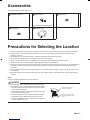
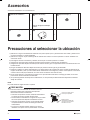
Accessories
Accessories supplied with the outdoor unit:
A Installation manual
1
B Drain socket
It is on the bottom packing case.
1
CDraincap(1)
6
DDraincap(2)
3
E Reducer assy
1
Precautions for Selecting the Location
1)Chooseaplacesolidenoughtobeartheweightandvibrationoftheunit,wheretheoperatingsoundwillnotbeamplied.
2)Choose a location where the hot air discharged from the unit or the operating sound will not cause a nuisance to the
neighbors of the user.
3)Avoid places near a bedroom and the like, so that the operating sound will cause no trouble.
4)Theremustbesufcientspacesforcarryingtheunitintoandoutofthesite.
5)Theremustbesufcientspaceforairpassageandnoobstructionsaroundtheairinletandtheairoutlet.
6)Thesitemustbefreefromthepossibilityofammablegasleakageinanearbyplace.
7)Installunits,powercords,andinter-unitwiresatleast10ft(3m)fromtelevisionandradiosets.(Thisistopreventinterference
toimagesandsounds.Noisemaybeexperiencedeveniftheyaremorethan10ft(3m)awaydependingonradiowave
conditions.)
8)In coastal areas or other places with salty atmosphere or one containing sulphate gas, corrosion may shorten the life of the
air conditioner.
9)Sincewaterwillowfromthedrainoftheoutdoorunit,donotplaceundertheunitanythingwhichmustbekeptawayfrom
moisture.
NOTE
Cannot be installed suspended from ceiling or stacked.
CAUTION
When operating the air conditioner in a low outdoor ambient
temperature, be sure to follow the instructions described below.
• To prevent exposure to wind, install the outdoor unit with its
suction side facing the wall.
• Never install the outdoor unit at a site where the suction side
may be exposed directly to wind.
• To prevent exposure to wind, it is recommended to install a
bafeplateontheairdischargesideoftheoutdoorunit.
• In heavy snowfall areas, select an installation site where the
snow will not affect the unit.
•Construct a large canopy.
•Construct a pedestal.
Install the unit high enough off
the ground to prevent burying
in snow.
01_EN_3P379970-4.indd 3 11/4/2014 2:50:06 PM

4■English
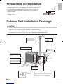
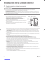
Precautions on Installation
• Check the strength and level of the installation surface so that the unit does not cause
any operating vibration or noise after installation.
• Inaccordancewiththefoundationdrawing,xtheunitsecurelybymeansofthe
foundation bolts. (Prepare 4 sets of M12 foundation bolts, nuts and washers; all
separatelyavailable.)
• Itisbesttoscrewinthefoundationboltsuntiltheirendsare3/4inch(20mm)fromthe
foundation surface.
3/4”
(20mm)
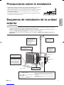
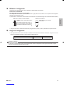
Outdoor Unit Installation Drawings
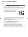
CAUTION
• Do not connect the embedded branch piping and the outdoor unit when only carrying out piping work without connecting the
indoor unit in order to add another indoor unit later.
Make sure no dirt or moisture gets into either side of the embedded branch piping.
Refer to “7. Refrigerant Piping Work” on page 11 for details.
• It is impossible to connect the indoor unit for one room only. Be sure to connect at least 2 rooms.
Cut thermal insulation pipe to
an appropriate length and
wrap it with tape, making sure
that no gap is left in the
insulation pipe’s cut line.
Wrap the insulation pipe
with finishing tape from
bottom to top.
9-13/16 (250) from wall
Allow space for piping
and electrical servicing.
Level mounting base
(available separately)
Where there is a danger of the
unit falling, use foot bolts, or
wires.
In sites with poor drainage, use
block bases for the outdoor unit.
Adjust foot height until the unit is
level. Otherwise, water leakage
or pooling of water may occur.
Also insulate the connection on the outdoor unit.
Use tape or insulating material on all connections to prevent air
from getting in between the copper piping and the insulation
tube.
Be sure to do this if the outdoor unit is installed above.
Stop valve cover
Service lid
13-5/8 (346)
(Foot bolt-hole
centers)
(Foot bolt-hole centers)
23-5/8 (600)
Allow 11-13/16” (300mm) of work
space below the ceiling surface.
Clamping material
Insulation tube
Stop valve cover
Tape
unit : inch (mm)
English
01_EN_3P379970-4.indd 4 11/4/2014 2:50:07 PM

5■English
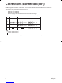
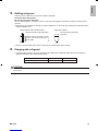
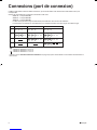
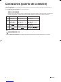
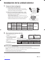
Connections (connection port)
Install the indoor unit according to the table below, which shows the relationship between the class of indoor unit and the
corresponding port.
The total indoor unit class that can be connected to this unit:
2MXS18* – Up to 24000 Btu
3MXS24* – Up to 39000 Btu
4MXS36* – Up to 48000 Btu
Thelinesetpipingsizeisdeterminedbythesizeoftheindoorunitttings.
Reducers are used at the outdoor unit to accommodate the correct gas line pipe size.
3MXS24∗4MXS36∗
Port 2MXS18∗
B07 , 09 , 12 , ,15 1807 , 09 , 12 , 15 07 , 09 , 12 , ,15 18
D07 , 09 , 12 , ,15 18 , 24
A07 , 09 ,12 07 , 09 ,12
07 , 09 ,12
C07 , 09 , 12 , ,15 18 07 , 09 , 12 , ,15 18
: Use a reducer to connect pipes.
: Use No. 2 and 4 reducers
: Use No. 5 and 6 reducers
: Use No. 1 and 3 reducers
#
# # #
######
# # #
###
Refer to “How to Use Reducers” on page 6 for information on reducer numbers and their shapes.
01_EN_3P379970-4.indd 5 11/4/2014 2:50:07 PM

6■English
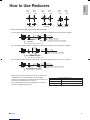
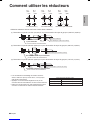
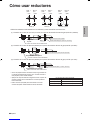
How to Use Reducers
• Use the reducers supplied with the unit as described below.
(1) Connecting a pipe of φ1/2 inch (12.7mm) to a gas pipe connection port for φ5/8 inch (15.9mm) :
(2) Connecting a pipe of φ3/8 inch (9.5mm) to a gas pipe connection port for φ5/8 inch (15.9mm) :
(3) Connecting a pipe of φ3/8 inch (9.5mm) to a gas pipe connection port for φ1/2 inch (12.7mm) :
No.1
φ5/8”
φ1/2”
No.2
φ1/2”
φ3/8”
No.3
φ5/8”
φ1/2”
No.4
φ1/2”
φ3/8”
No.5
φ5/8”
φ3/8”
No.6
φ5/8”
φ3/8”
Gasket (1) Gasket (2) Reduce and gasket
No. 1
No. 3 Flare nut (for φ5/8 inch (15.9mm))
Inter-unit piping
Connection port of outdoor unit
Connection port of outdoor unit
Connection port of outdoor unit
Be sure to attach
the gasket.
No. 5
No. 6
Flare nut (for φ3/8 inch (9.5mm))
Be sure to attach the gasket.
No. 4
No. 2 Flare nut (for φ1/2 inch (12.7mm))
Be sure to attach the gasket.
Flare nut tightening torque
φ3/8 inch (9.5mm)
φ1/2 inch (12.7mm)
φ5/8 inch (15.9mm)
24-1/8 – 29-1/2ft • Ibf (32.7-39.9N • m)
36-1/2 – 44-1/2ft • lbf (49.5-60.3N • m)
45-5/8 – 55-5/8ft • lbf (61.8-75.4N • m)
• When using the reducer packing shown above, be careful not to
overtighten the nut, or the smaller pipe may be damaged.
• Apply a coat of refrigeration oil to the threaded connection port of
theoutdoorunitwherethearenutcomesin.
• Use an appropriate wrench to avoid damaging the connection
threadbyovertighteningthearenut.
English
01_EN_3P379970-4.indd 6 11/4/2014 2:50:07 PM

7■English
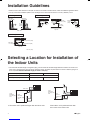
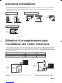
Installation Guidelines
• Whereawallorotherobstacleisinthepathofoutdoorunit’sintakeorexhaustairow,followtheinstallationguidelinesbelow.
• Foranyofthebelowinstallationpatterns,thewallheightontheoutletsideshouldbe47-1/4inch(1200mm)orless.
unit: inch (mm)
Top view
More than 3-15/16 (100)
More than 13-3/4 (350)
More than
1-15/16 (50)
More than
1-15/16 (50)
More than
1-15/16 (50)
Top view
More
than
3-15/16
(100)
More than
13-3/4
(350)
More than
3-15/16 (100) More than
13-3/4 (350)
Side view
47-1/4
(1200)
or less
Wall facing one side Walls facing two sides
Walls facing three sides
More than
3-15/16 (100)
More than
13-3/4 (350)
Selecting a Location for Installation of
the Indoor Units
• The maximum allowable length of refrigerant piping, and the maximum allowable height difference between the outdoor and
indoor units, are listed below. (The shorter the refrigerant piping, the better the performance. Connect so that the piping is as
short as possible. Shortest allowable length per room is 10ft (3m).)
If the outdoor unit is positioned higher than the indoor units. If the outdoor unit is positioned lower than
one or more of the indoor units.
Level
difference:
24-5/8ft (7.5m)
max.
Level
difference:
49-1/4ft (15m)
max.
Indoor Unit
Outdoor Unit Level
difference:
49-1/4ft (15m)
max.
Outdoor Unit
Indoor Unit
Level
difference:
24-5/8ft (7.5m)
max.
Outdoor unit capacity class
Piping to each indoor unit
2MXS18∗
82ft (25m) max.
3MXS24∗, 4MXS36∗
Total length of piping between all units 164ft (50m) max. 230ft (70m) max.
01_EN_3P379970-4.indd 7 11/4/2014 2:50:08 PM

8■English
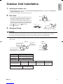
Outdoor Unit Installation
1. Installing the outdoor unit
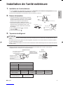
1)When installing the outdoor unit, refer to “Precautions for Selecting the Location” on page 3 and the “Outdoor Unit
Installation Drawings” on page 4.
2)If drain work is necessary, follow the procedures below.
2. Drain work
• Ifthedrainportiscoveredbyamountingbaseoroor
surface, place additional foot bases of at least 1-1/4
inch(30mm)inheightundertheoutdoorunit’sfeet.
• Incoldareas,donotuseadrainsocket,draincaps(1,2)
and a drain hose with the outdoor unit. (Otherwise, the
drainwatermayfreeze,impairingheatingperformance.)
1)Attach Cdraincap(1)and Ddraincap(2).
2)Attach B drain socket.
3. Refrigerant Piping
CAUTION
• Usethearenutxedtothemainunit.(Thisistopreventcrackingofthearenutasaresultofdeteriorationovertime.)
• Topreventgasleakage,applyrefrigerationoilonlytotheinnersurfaceoftheare.(UserefrigerationoilforR410A.)
• Useatorquewrenchwhentighteningthearenutstopreventdamagetothearenutsandgasleakage.
• Alignthecentersofbotharesandtightenthearenuts3or4turnsbyhand.Thentightenthemfullywithaspanneranda
torque wrench.
Do not apply refrigeration
oil to the outer surface.
Flare nut
Apply refrigeration
oil to the inner
surface of the flare.
Do not apply refrigeration oil to
the flare nut to avoid tightening
with excessive torque.
Apply oil
Torque wrench
Piping union
Flare nut
Spanner
Tighten
Flare nut tightening torque
φ1/4 inch (6.4mm)
φ3/8 inch (9.5mm)
φ1/2 inch (12.7mm)
φ5/8 inch (15.9mm)
10-1/2 – 12-3/4ft • lbf (14.2-17.2N • m)
24-1/8 – 29-1/2ft • Ibf (32.7-39.9N • m)
36-1/2 – 44-1/2ft • lbf (49.5-60.3N • m)
45-5/8 – 55-5/8ft • lbf (61.8-75.4N • m)
Width across flats
Valve cap tightening torque
Service port cap tightening torque 8–10-7/8ft • lbf
(10.8-14.7N • m)
11/16 inch (17mm)
10-1/2 – 12-5/8ft • lbf
(14.2-17.2N • m)
3/4 inch (19mm)
12-5/8–15-3/8ft • lbf
(17.1-20.9N • m)
7/8 inch (22mm)
16–20-1/4ft • lbf
(21.6-27.4N • m)
1-1/16 inch (27mm)
35-3/8 – 44-1/8ft • lbf
(48-59.8N • m)
Bottom frame
Drain cap
Pinch the bottom
frame in.
Drain cap (1)
Drain cap (2)
DDrain cap (2)
Air outlet side
BDrain
socket
C
D
Bottom frame
Drain socket
Hose (available commercially,
inner dia. 5/8 ” (16mm))
B
English
01_EN_3P379970-4.indd 8 11/4/2014 2:50:08 PM

9■English
Outdoor Unit Installation
4. Pressure test and evacuating system
WARNING
• Donotmixanysubstanceotherthanthespeciedrefrigerant(R410A)intotherefrigerationcycle.
• If refrigerant gas leaks should occur, ventilate the room as soon and as much as possible.
• R410A, as well as other refrigerants, should always be recovered and never be released directly into the environment.
• Use a vacuum pump for R410A exclusively. Using the same vacuum pump for different refrigerants may damage the vacuum
pump or the unit.
• When piping work is complete, it is necessary to perform a pressure test
and evacuate system with a vacuum pump.
• If using additional refrigerant, perform air purging of the refrigerant pipes
and indoor unit using a vacuum pump, then charge additional refrigerant.
• Useahexagonalwrench(3/16inch(4mm))tooperatethestopvalverod.
• All refrigerant pipe joints should be tightened with a torque wrench to the
speciedtighteningtorque.
Compound
pressure gauge
Pressure
meter
High-pressure
valve
Low-pressure
valve
Vacuum pump
Service port
Liquid
stop
valve
Valve caps
Gas stop valve
Charging
hoses
Gauge
manifold
1)Pressurizetheliquidpipeandgaspipefromtheserviceportsofeachstopvalveto550psi(3.8MPa)(donotpressurize
morethan550psi(3.8MPa))for1hourminimum,24hoursrecommended.Ifthereisapressuredrop,checkforleaks,
make repairs and perform the pressure test again.
2)Connectprojectionsideofcharginghose(whichcomesfromgaugemanifold)togasstopvalve’sserviceport.
3)Fullyopengaugemanifold’slow-pressurevalve(Lo)andcompletelycloseitshigh-pressurevalve(Hi).
(High-pressurevalvesubsequentlyrequiresnooperation.)
4)Evacuate system using vacuum pump to below 500 microns for 1 hour minimum.
5)Closegaugemanifold’slow-pressurevalve(Lo)andstopvacuumpump.
(Leave as is for 4-5 minutes and make sure the coupling meter needle does not go back.
If it does go back, this may indicate the presence of moisture or leaking from connecting parts. After inspecting all the
connectionandlooseningthenretighteningthenuts,repeatsteps3-5.)
6)Remove covers from liquid stop value and gas stop valve.
7)Turn the liquid stop valve’s rod 90° counter-clockwise with a hexagonal wrench to open the valve.
Close it after 5 seconds, and check for gas leakage.
Usingsoapywater,checkforgasleakagefromindoorunit’sareandoutdoorunit’sareandvalverods.
After the check is complete, wipe all soapy water off.
8)Disconnect charging hose from gas stop valve’s service port, then fully open liquid and gas stop valves.
(Donotattempttoturnvalverodbeyonditsstop.)
9)Tightenvalvecapsandserviceportcapsfortheliquidandgasstopvalveswithatorquewrenchtothespeciedtorques.
Refer to “3. Refrigerant Piping” on page 8 for details.
01_EN_3P379970-4.indd 9 11/4/2014 2:50:08 PM

10■English
5. Relling refrigerant
Check the type of refrigerant to be used on the machine nameplate.
Precautions when adding R410A
Fill from the liquid pipe in liquid form.
This is a mixed refrigerant, so adding it in gas form may cause the refrigerant composition to change, preventing normal
operation.
1)Beforelling,checkwhetherthecylinderhasasiphonattachedornot.(Itshouldhavesomethinglike“liquidllingsiphon
attached”displayedonit.)
Filling a cylinder with an attached siphon
Stand the cylinder upright when filling.
There is a siphon pipe inside, so the
cylinder need not be upside-down to
fill with liquid.
Filling other cylinders
Turn the cylinder upside-down
when filling.
• Be sure to use the R410A tools to ensure pressure and to prevent foreign objects entering.
6. Charging with refrigerant
• Ifthetotallengthofpipingforallroomsexceedsthegurelistedbelow,additionallychargewith0.21oz/ft(20g/m)of
refrigerant(R410A)foreachadditionalpipinglength.
Outdoor unit capacity class
Total length of piping for all rooms
3MXS24∗, 4MXS36∗
131-5/8ft (40m)
2MXS18∗
98-3/8ft (30m)
CAUTION
Eventhoughthestopvalveisfullyclosed,therefrigerantmayslowlyleakout;donotleavethearenutremovedforalong
period of time.
English
01_EN_3P379970-4.indd 10 11/4/2014 2:50:09 PM

11 ■English
Outdoor Unit Installation
7. Refrigerant piping work
7-1. Cautions on pipe handling
• Protect the open end of the pipe against dust and moisture.
• All pipe bends should be as gentle as possible. Use a pipe bender for
bending.
7-2. Selection of copper and heat insulation materials
Whenusingcommercialcopperpipesandttings,observethefollowing:
• Insulation material: Polyethylene foam
Heattransferrate:0.041to0.052W/mK(0.024to0.030Btu/fth°F
(0.035to0.045kcal/mh°C))
BesuretouseinsulationthatisdesignedforusewithHVACSystems.
• Be sure to insulate both the gas and liquid piping and observe the
insulation dimensions as below.
Wall
If no flare cap is
available, cover
the flare mouth
with tape to keep
dirt and water out.
Be sure to
place a cap.
Rain
Gas pipe Liquid pipe
Gas pipe
insulation
Liquid pipe
insulation
Finishing tape Drain hose
Inter-unit wire
Gas side
Piping size
O.D. 3/8 inch
(9.5mm)
O.D. 1/2 inch
(12.7mm)
O.D. 5/8 inch
(15.9mm)
O.D. 1/4 inch
(6.4mm)
1-3/16 inch (30mm)
or more
1-9/16 inch (40mm)
or more
1-15/16 inch (50mm)
or more
1-3/16 inch (30mm)
or more
0.031 inch (0.8mm)
(C1220T-O)
0.039 inch (1.0mm)
(C1220T-O)
0.031 inch (0.8mm)
(C1220T-O)
I.D. 15/32-19/32 inch
(12-15mm)
I.D. 9/16-5/8 inch
(14-16mm)
I.D. 5/8-13/16 inch
(16-20mm)
I.D. 5/16-13/32 inch
(8-10mm)
13/32 inch
(10mm) Min.
Minimum bend radius
Piping thickness
Thermal insulation size
Thermal insulation
thickness
Liquid side
• Use separate thermal insulation pipes for gas and liquid refrigerant pipes.
8. Flaring the pipe end
1)Cut the pipe end with a pipe cutter.
2)Remove burrs with the cut surface facing downward
so that the chips do not enter the pipe.
3)Putthearenutonthepipe.
4)Flare the pipe.
5)Checkthatthearingisproperlymade.
Check
Flare’s inner
surface must
be flaw-free.
The pipe end must
be evenly flared in
a perfect circle.
Make sure that the
flare nut is fitted.
Set exactly at the position shown below. Flaring
A
Die A0-0.020 inch
(0-0.5mm)
Clutch-type
Flare tool for R410A
0.039-0.059 inch
(1.0-1.5mm)
Clutch-type (Rigid-type)
0.059-0.079 inch
(1.5-2.0mm)
Wing-nut type (Imperial-type)
Conventional flare tool
Cut exactly at
right angles. Remove burrs.
WARNING
• Donotusemineraloilonaredpart.
• Prevent mineral oil from getting into the system as this would reduce the lifetime of the units.
• Never use piping which has been used for previous installations. Only use parts which are delivered with the unit.
• Never install a drier to this R410A unit in order to guarantee its lifetime.
• The drying material may dissolve and damage the system.
• Incompletearingmaycauserefrigerantgasleakage.
01_EN_3P379970-4.indd 11 11/4/2014 2:50:09 PM

12■English
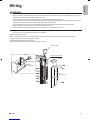
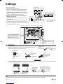
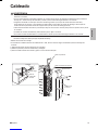
Wiring
WARNING
• Donotusetappedwires,extensioncords,orstarburstconnections,astheymaycauseoverheating,electricalshock,orre.
• Do not use locally purchased electrical parts inside the product. (Do not branch the power for the drain pump, etc., from the
terminalblock.)Doingsomaycauseelectricshockorre.
• Besuretoinstallagroundfaultcircuitinterrupter.(Onethatcanhandlehigherharmonics.)
(This unit uses an inverter, which means that a ground fault circuit interrupter capable of handling harmonics must be used
inordertopreventanymalfunctionofthegroundfaultcircuitinterrupteritself.)
• Useanall-poledisconnectiontypecircuitbreakerwithatleast1/8inch(3mm)betweenthecontactpointgaps.
• When carrying out wiring connection, take care not to pull at the conduit.
• Donotconnectthepowerwiretotheindoorunit.Doingsomaycauseelectricshockorre.
• Do not turn on the circuit breaker until all work is completed.
<Method of Mounting Conduit>
•When connecting indoor units for 3 rooms or more, open knockout holes without deforming the conduit mounting plate.
1)Dismount the service lid by removing the 2 screws.
2)Slide the protection plate up and remove it.
3)Pass wires through the conduit and secure them with a lock nut.
Stop valve cover
Service lid
Conduit mounting plate
Protection plate
Lock nut
Conduit
mounting plate
Conduit
Knockout hole
English
01_EN_3P379970-4.indd 12 11/4/2014 2:50:10 PM

13 ■English
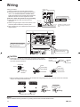
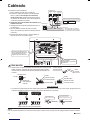
Wiring
<Wiring procedure>
1)Striptheinsulationfromthewire(3/4inch(20mm)).
2)Connect the connection wires between the indoor and
outdoor units so that the terminal numbers match.
Tighten the terminal screws securely. We recommend a
atheadscrewdriverbeusedtotightenthescrews.
3) Be sure to match the symbols for wiring and piping.
4)Pull the wire lightly to make sure that it does not
disconnect.
5)Pass the wiring through the cutout on the bottom of the
protection plate and attach the protection plate.
6)After completing the work, reattach the service lid to its
original position.
Circuit breaker
Ground fault circuit
interrupter
Outdoor unit
60Hz 208/230V
Be sure to use the dedicated circuits.
To room B
To room C
To room D
Use AWG 16 or AWG 14 wire for
the power supply and inter-unit
wires.
Room
A
Room A
Room
CRoom
D
Room
B
Indoor unit
If the length of a connection wire
is 33ft (10m) or more, use AWG14 wire.
power supply
Shape the wires so that there is
no lifting of the service hatch or
other structural parts.
Use the specified wires and
connect them securely.
Room A
Room C
Room D
Room B
power supply
CAUTION
• Precautions to be taken for power supply wiring. When using stranded
wires, make sure to use the round crimp-style terminal for connection to
the power supply terminal block.
Stranded
wire
Round crimp-style
terminal
Arrow view B
Flat washer
Screw
Round
crimp-style
terminal
Good
Round crimp-
style terminal
Flat washer
Screw
Wrong
Flat washer
Round crimp-
style terminal
Screw
B
Good
Round crimp-
style terminal
Flat washer
Screw
Wrong
Flat washer
Round crimp-
style terminal
Screw
Flat washer
Screw
Round
crimp-style
terminal
A
Arrow view A
• When connecting the inter-unit wires to the terminal block using a single core wire, be sure to curl the end of the lead.
Improperworkmaycauseheatandres.
Strip wire end
to this point.
Excessive strip length
may cause electric shock
or current leakage.
Stripping wire at terminal block
Good Wrong
Good Wrong
Ground
This air conditioner must be grounded. For grounding, follow all local, and state electrical codes.
01_EN_3P379970-4.indd 13 11/4/2014 2:50:10 PM

14■English
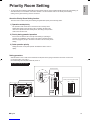
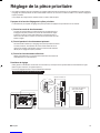
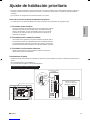
Priority Room Setting
• To use Priority Room Setting, initial settings must be made when the unit is installed. Explain the Priority Room Setting, as
describedbelow,tothecustomer,andconrmwhetherornotthecustomerwantstousePriorityRoomSetting.
Setting it in the guest and living rooms is convenient.
About the Priority Room Setting function
The indoor unit for which Priority Room Setting is applied takes priority in the following cases.
1) Operation mode priority
The operation mode of the indoor unit which is set for Priority Room
Setting takes priority. If the set indoor unit is operating, all other indoor
units do not operate and enter standby mode, according to the operation
mode of the set indoor unit.
2) Priority during powerful operation
If the indoor unit which is set for Priority Room Setting is operating at
powerful, the capabilities of other indoor units will be somewhat reduced.
Power supply gives priority to the indoor unit which is set for Priority Room
Setting.
3) Quiet operation priority
Setting the indoor unit to quiet operation will make the outdoor unit run
quietly.
Setting procedure
Slide the switch to the on side for the switch that corresponds to the piping connected to the indoor unit to be set.
(Inthegurebelow,itisroomA.)
Once the settings are complete, switch the power on.
Be sure to only set one room
Service PC-board
HEAT
COOL
4
3
2
1
2
1
E
D
C
B
A
COOL
4
3
2
1
2
1
E
D
C
B
AScrew
Remove
the switch
cover
ON OFF
Priority room setting switch (SW4)
E
D
C
B
A
English
01_EN_3P379970-4.indd 14 11/4/2014 2:50:10 PM

15 ■English
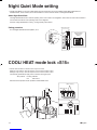
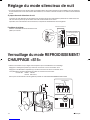
Night Quiet Mode setting
• If Night Quiet Mode is to be used, initial settings must be made when the unit is installed. Explain Night Quiet Mode, as
describedbelow,tothecustomer,andconrmwhetherornotthecustomerwantstouseNightQuietMode.
About Night Quiet Mode
The Night Quiet Mode function reduces operating noise of the outdoor unit at nighttime. This function is useful if the customer is
worried about the effects of the operating noise on the neighbors.
However,ifNightQuietModeisrunning,coolingcapacitywillbesaved.
Setting procedure
TurntheNightQuietModeswitch(SW6-1)toon.
Service PC-board
HEAT
COOL
4
3
2
1
2
1
E
D
C
B
A
Night Quiet Mode
setting switch
(SW6-1)
2
1
ON OFF
COOL
4
3
2
1
2
1
E
D
C
B
AScrew
Remove
the switch
cover
COOL/ HEAT mode lock <S15>
• Use the S15 connector to set the unit to only cool or heat.
Settingtoonlyheat(H):short-circuitpins1and3oftheconnector<S15>
Settingtoonlycool(C):short-circuitpins3and5oftheconnector<S15>
Thefollowingspecicationsapplytotheconnectorhousingandpins.
JSTproducts Housing:VHR-5N
Pin: SVH-21T-1,1
NotethatforcedoperationisalsopossibleinCOOL/HEATmode.
COOL mode (C)
HEAT mode (H)
1 3 5
01_EN_3P379970-4.indd 15 11/4/2014 2:50:11 PM

16■English
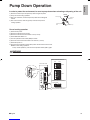
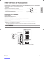
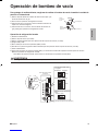
Pump Down Operation
In order to protect the environment, be sure to pump down when relocating or disposing of the unit.
1)Remove the valve cap from liquid stop valve and gas stop valve.
2)Carry out forced cooling operation.
3)After 5 to 10 minutes, close the liquid stop valve with a hexagonal
wrench.
4)After 2 to 3 minutes, close the gas stop valve and stop forced
cooling operation.
Gas stop valve
Close
Hexagonal
wrench
Liquid stop
valve Valve cap
Forced cooling operation
1)Switch off the power.
2)RemovetheServicelid(2screws).
3)RemovetheservicePC-boardswitchcover(1screw).
4)Switch SW5 and SW6 to off.
5)Turntheoperationmodeswitch(SW2)toCOOL.
6)ScrewtheservicePC-boardswitchcoverbackon(1screw).
7)Switch the power on.
8)Pushtheforcedoperationswitch(SW1)abovetheservicePC-boardcover.
Start forced cooling operation.
Tostopforcedoperation,pushtheforcedoperationswitch(SW1)again.
WARNING
Donotremovetheswitchcoverunlessthepowerhasbeenturnedoff.(Riskofelectricshock)
Service PC-board
HEAT
COOL
4
3
2
1
2
1
E
D
C
B
A
•Switch SW5 and SW6 to off.
2
1
ON OFF
4
3
ON OFF
2
1
•Set to COOL.
Forced operation switch (SW1)
HEAT
COOL
Operation mode switch (SW2)
SW6
SW5
COOL
4
3
2
1
2
1
E
D
C
B
AScrew
Remove
the switch
cover
English
01_EN_3P379970-4.indd 16 11/4/2014 2:50:11 PM

17 ■English
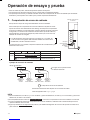
Trial Operation and Testing
• Before starting the test run, measure the voltage at the primary side of the circuit breaker.
• Check that all liquid and gas stop valves are fully open.
• Check that piping and wiring all match. The wiring error check can be conveniently used for underground wiring and other wiring
that cannot be directly checked.
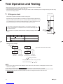
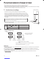
1. Wiring error check
This product is capable of automatic correction of wiring error.
PressthewiringerrorcheckswitchontheoutdoorunitservicePC-board.However,the
wiring error check switch will not function for 3 minutes after the safety breaker is turned
on,ordependingontheoutsideairconditions(SeeNote2.).About15-20minutesafter
the switch is pressed, the errors in the connection wiring will be corrected.
The service monitor LEDs indicate whether or not correction is possible, as
shown in the table below. For details about how to read the LED display, refer to
the service manual.
If self-correction is not possible, check the indoor unit wiring and piping in the usual
manner.
Service PC-board
A
1
2
3
4
5
Wiring error
check switch
(SW3)
LED
Status
1 2 3 4
All Flashing Automatic correction impossible
Automatic correction completed
Abnormal stop [Note. 4]
Message
Flashing One after another
(One or more of LEDs 1 to 4 are ON)
Terminal block
Wiring error check
LED lighting sequence after a wiring correction.
Order of LED flashing: 2 1 3 4
From Room C
to the “kitchen”
From Room B
to the “living room”
From Room D
to the “children’s room”
From Room A
to the “bedroom”
Wiring correct example
The figure at left shows branch wiring.
NOTE
1)For two rooms, LED 3,4 and 5 are not displayed, and for three rooms, LED 4 and 5 is not displayed, and for four rooms,
LED 5 is not displayed.
2)If the outside air temperature is 41°F(5°C)orless , the wiring error check function will not operate.
3)After wiring error check operation is completed, LED indication will continue until ordinary operation starts. This is normal.
4)Follow the product diagnosis procedures. (Details of product error diagnosis are listed on the back of the
right side plate .)
01_EN_3P379970-4.indd 17 11/4/2014 2:50:11 PM

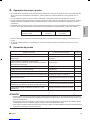
18■English
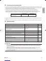
2. Trial operation and testing
• To test cooling, set for the lowest temperature. To test heating, set for the highest temperature. (Depending on the room
temperature,onlyheatingorcooling(butnotboth)maybepossible.)
• Aftertheunitisstopped,itwillnotstartagain(heatingorcooling)forabout3minutes.
• Duringthetestrun,rstchecktheoperationofeachunitindividually.Thenalsocheckthesimultaneousoperationofallindoor
units. Check both heating and cooling operation.
• After running the unit for about 20 minutes, measure the temperatures at the indoor unit inlet and outlet. If the measurements are
above the values shown in the table below, then they are normal.
Temperature difference between
inlet and outlet About 14°F (8°C)
Cooling
About 36°F (20°C)
Heating
(When running in one room)
• During cooling operation, frost may form on the gas stop valve or other parts. This is normal.
• Operate the indoor units in accordance with the included operation manual. Check that they operate normally.
3. Test items
Are the indoor units installed securely?
Has an inspection been made to check for gas leakage?
Has complete thermal insulation been done (gas pipes, liquid
pipes, indoor portions of the drain hose extension)?
Is the drainage secure?
Are the ground wire connections secure?
Are the electric wires connected correctly?
Is the wiring in accordance with the specifications?
Are the inlets/outlets of the indoor and outdoor units free of any obstructions?
Are the stop valves open?
Do the marks match (room A, room B, room C, room D) on the
wiring and piping for each indoor unit?
Is the priority room setting set for 2 or more rooms?
Test item CheckConsequences of trouble
Fall, vibration, noise
Incomplete cooling/heating function
Water leakage
Water leakage
Electrical leakage
Incomplete cooling/heating function
No operation or burn damage
Incomplete cooling/heating function
Incomplete cooling/heating function
Incomplete cooling/heating function
The priority room setting will not function.
ATTENTION
• Havethecustomeractuallyoperatetheunitwhilelookingatthemanualincludedwiththeindoorunit.Instructthecustomer
howtooperatetheunitcorrectly(particularlycleaningoftheairlters,operationprocedures,andtemperatureadjustment).
• Even when the air conditioner is not operating, it consumes some electric power. If the customer is not going to use the unit
soon after it is installed, turn off the circuit breaker to avoid wasting electricity.
• If additional refrigerant has been charged because of long piping, list the amount added on the nameplate on the reverse
side of the stop valve cover.
English
01_EN_3P379970-4.indd 18 11/4/2014 2:50:12 PM

1
■Français
Sommaire
Considérations sur la sécurité ...................... 1
Accessoires ..................................................... 3
Précautions pour la sélection de l'emplacement ...
3
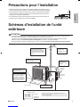
Précautions pour l'installation ...................... 4
Schémas d'installation de l'unité extérieure
... 4
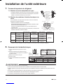
Connexions (port de connexion) ................... 5
Comment utiliser les réducteurs ................... 6
Directives d'installation ................................. 7
Sélection d'un emplacement pour l'installation
des unités intérieures ..................................... 7
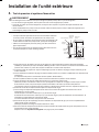
Installation de l'unité extérieure .................... 8
1. Installation de l'unité extérieure ................................... 8
2. Travaux d'évacuation ................................................... 8
3. Tuyauterie de réfrigérant.............................................. 8
4. Test de pression et système d'évacuation ................... 9
5. Remplissage du réfrigérant ......................................... 10
6. Charge avec du réfrigérant .......................................... 10
7. Travaux de tuyauterie de réfrigérant ........................... 11
8. Évasement de l'extrémité du tuyau .............................. 11
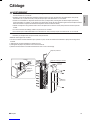
Câblage ............................................................ 12
Réglage de la pièce prioritaire ....................... 14
Réglage du mode silencieux de nuit ............. 15
Verrouillage du mode REFROIDISSEMENT/
CHAUFFAGE <S15> ........................................ 15
Intervention d'évacuation .............................. 16
Fonctionnement d'essai et test ..................... 17
1. Contrôle d'erreur de câblage ....................................... 17
2. Fonctionnement d'essai et test .................................... 18
3. Éléments testés ........................................................... 18
Considérations sur la sécurité
• Lisez attentivement ces Considérations sur la sécurité
pour assurer une installation correcte.
• Ce manuel classe les précautions de la manière suivante
DANGER, AVERTISSEMENT et ATTENTION.
Assurez-vous de suivre toutes les précautions ci-dessous:
elles sont toutes essentielles pour assurer la sécurité.
DANGER ........... Indique une situation extrêmement
dangereuse qui, si elle n'est pas
évitée, entraînera la mort ou des
blessures graves.
AVERTISSEMENT
... Le non-respect de l'une des
précautions AVERTISSEMENT
est susceptible d'entraîner des
conséquences aussi dramatiques
que la mort ou de graves blessures.
ATTENTION ...... Le non-respect de l'une des
précautions ATTENTION peut, dans
certains cas, entraîner de graves
conséquences.
• Après avoir terminé l'installation, testez l'unité pour
vérierqu'iln'yapasd'erreurdansl'installation.Donnez
à l'utilisateur les instructions adéquates concernant
l'utilisation et le nettoyage de l'unité conformément au
manuel d'utilisation.
DANGER
• Le gaz réfrigérant est plus lourd que l'air et remplace
l'oxygène. Une fuite importante peut conduire à un
appauvrissement en oxygène, en particulier en sous-sol,
et un risque d'asphyxie peut survenir et entraîner des
blessures graves ou la mort.
•
Si vous constatez des fuites de gaz réfrigérant pendant
l'installation, aérez immédiatement la zone.
Le gaz réfrigérant peut produire un gaz toxique s'il entre en
contactavecuneammecommeàpartird'unventilateur
de chauffage, une cuisinière ou un appareil de cuisson.
L'exposition à ce gaz peut provoquer des blessures graves
ou la mort.
•
Aprèsl'achèvementdestravauxd'installation,vériezque
le gaz réfrigérant ne fuit pas.
Le gaz réfrigérant peut produire un gaz toxique s'il entre en
contactavecuneammecommeàpartird'unventilateur
de chauffage, une cuisinière ou un appareil de cuisson.
L'exposition à ce gaz peut provoquer des blessures graves
ou la mort.
• Ne reliez pas les unités à des conduites d'eau, à des
câbles téléphoniques ou à des paratonnerres, car une
mise à la terre incomplète peut provoquer un risque
d'électrocution important pouvant entraîner des blessures
graves ou la mort; ne les reliez pas non plus à des tuyaux
de gaz car une fuite de gaz peut provoquer une explosion
et entraîner des blessures graves ou la mort.
02_FR_3P379970-4.indd 1 14/11/05 11:40:21 AM
La page charge ...
La page charge ...
La page charge ...
La page charge ...
La page charge ...
La page charge ...
La page charge ...
La page charge ...
La page charge ...
La page charge ...
La page charge ...
La page charge ...
La page charge ...
La page charge ...
La page charge ...
La page charge ...
La page charge ...
La page charge ...
La page charge ...
La page charge ...
La page charge ...
La page charge ...
La page charge ...
La page charge ...
La page charge ...
La page charge ...
La page charge ...
La page charge ...
La page charge ...
La page charge ...
La page charge ...
La page charge ...
La page charge ...
La page charge ...
La page charge ...
La page charge ...
-
 1
1
-
 2
2
-
 3
3
-
 4
4
-
 5
5
-
 6
6
-
 7
7
-
 8
8
-
 9
9
-
 10
10
-
 11
11
-
 12
12
-
 13
13
-
 14
14
-
 15
15
-
 16
16
-
 17
17
-
 18
18
-
 19
19
-
 20
20
-
 21
21
-
 22
22
-
 23
23
-
 24
24
-
 25
25
-
 26
26
-
 27
27
-
 28
28
-
 29
29
-
 30
30
-
 31
31
-
 32
32
-
 33
33
-
 34
34
-
 35
35
-
 36
36
-
 37
37
-
 38
38
-
 39
39
-
 40
40
-
 41
41
-
 42
42
-
 43
43
-
 44
44
-
 45
45
-
 46
46
-
 47
47
-
 48
48
-
 49
49
-
 50
50
-
 51
51
-
 52
52
-
 53
53
-
 54
54
-
 55
55
-
 56
56


Daikin 4MXS36NMVJU Guide d'installation
- Catégorie
- Climatiseurs split-system
- Taper
- Guide d'installation
dans d''autres langues
- English: Daikin 4MXS36NMVJU Installation guide
- español: Daikin 4MXS36NMVJU Guía de instalación
Documents connexes
Autres documents
-
Haier HSU12VHJDBW Guide d'installation
-
-
MRCOOL MULTI4-36HP230V1 Guide d'installation
-
Mitsubishi Electric MSZ-GS15NA-U1 Mini Split Heat Pump Systems Manuel utilisateur
-
Toshiba MCY-MAP0601HT Le manuel du propriétaire
-
Fujitsu UOMH18AFXZJ Guide d'installation
-
Fujitsu AOU48RLXFZ1 Guide d'installation
-
NaturaLED 9281 LED Vapor Tight Guide d'installation