Vulcan HD Series Range Mode d'emploi
- Catégorie
- Cheminées
- Taper
- Mode d'emploi

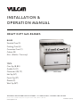
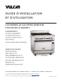
INSTALLATION &
OPERATION MANUAL
HEAVY DUTY GAS RANGES
BASES:
Standard Oven (S)
Finishing Oven (H)
Convection Oven (C)
Cabinet (B)
None (Modular / Countertop)
TOPS:
Oven Top (B, BU)
Griddle (G, GT)
Charbroiler (CB, TC)
Hot Top (HT)
French Top (FT)
Plancha (P)
Work Top (WT)
F-51056 Rev. A (09-23)
Vulcan is a division of ITW Food Equipment Group | 3600 North Point Blvd., Baltimore, MD 21222
vulcanequipment.com
TECHNICAL SERVICE AND PARTS ASSISTANCE - US: 1-800-814-2028 | CANADA: 1-800-444-4764
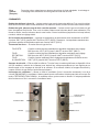
Model V6B36S

- 2 -
IMPORTANT FOR YOUR SAFETY
THIS MANUAL HAS BEEN PREPARED FOR PERSONNEL QUALIFIED TO INSTALL GAS
EQUIPMENT, WHO SHOULD PERFORM THE INITIAL FIELD START-UP AND
ADJUSTMENTS OF THE EQUIPMENT COVERED BY THIS MANUAL.
POST IN A PROMINENT LOCATION THE INSTRUCTIONS TO BE FOLLOWED IN THE
EVENT THE SMELL OF GAS IS DETECTED. THIS INFORMATION CAN BE OBTAINED
FROM THE LOCAL GAS SUPPLIER.
IMPORTANT
In the event a gas odor is detected, shut
down units at main shutoff valve and contact
the local gas supplier for service.
FOR YOUR SAFETY
Do not store or use gasoline or other
flammable vapors or liquids in the vicinity of
this or any other appliance.
Improper installation, adjustment, alteration,
service or maintenance can cause property
damage, injury or death. Read the
installation, operating and maintenance
instructions thoroughly before installing or
servicing this equipment.
IN THE EVENT OF A POWER FAILURE, DO NOT
ATTEMPT TO OPERATE THIS DEVICE.

- 3 -
CONTENTS
INSTALLATION ....................................................................................................................................... 4
UNPACKING ......................................................................................................................................... 4
LOCATION ............................................................................................................................................ 4
INSTALLATION CODES AND STANDARDS ................................................................................... 5
LEG/CASTER INSTALLATION .......................................................................................................... 6
LEVELING ............................................................................................................................................. 6
GAS CONNECTIONS ........................................................................................................................... 9
TESTING THE GAS SUPPLY SYSTEM ........................................................................................... 10
ELECTRICAL CONNECTIONS ......................................................................................................... 10
OPERATION ............................................................................................................................................ 11
BEFORE FIRST USE ........................................................................................................................... 11
CONTROLS ......................................................................................................................................... 12
LIGHTING PILOTS AND VERIFYING BURNER OPERATION .................................................... 13
SHUTTING DOWN ............................................................................................................................. 15
OPERATING SUGGESTIONS............................................................................................................ 15
LOADING AND UNLOADING THE OVEN ..................................................................................... 16
CLEANING .............................................................................................................................................. 17
REGULAR CLEANING ...................................................................................................................... 17
EXTERIOR CLEANING ..................................................................................................................... 18
MAINTENANCE & ADJUSTMENTS .................................................................................................... 20
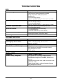
TROUBLESHOOTING ............................................................................................................................ 21

- 4 -
INSTALLATION, OPERATION, AND CARE OF VULCAN
HEAVY DUTY GAS RANGES
PLEASE KEEP THIS MANUAL FOR FUTURE USE
GENERAL
Vulcan Heavy Duty Gas Ranges are produced with quality workmanship and material. These ranges are
designed with efficiency in cooking performance, sanitation, and ease of cleaning ability in mind. Proper
installation, usage, and maintenance of your range will result in many years of satisfactory performance.
The manufacturer suggests that you thoroughly read this entire manual and carefully follow all the
instructions provided.
Reference manual F961533 for refrigerated base setups.
INSTALLATION
UNPACKING
This range was inspected before leaving the factory. The transportation company assumes full
responsibility for safe delivery upon acceptance of the shipment. Immediately after unpacking, check for
possible shipping damage. If the range is found to be damaged, save the packaging material and contact
the carrier within 5 days of delivery.
Carefully unpack range(s) and place in the approximate installation position. Remove parts packed in a
small cardboard box from oven cavity or shipped separately in finishing kit.
If burner has been shipped using any package strapping devices, remove these before installing the
range.
Before installing, check the type of gas supply (natural or propane) to make sure they agree with the
specifications on the rating plate located on the inside of the kick panel. If the supply and equipment
requirements do not agree, do not proceed with the installation. Contact your dealer immediately.
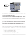
LOCATION
The equipment area must be kept free and clear of combustible substances.
Installation clearances: COMBUSTIBLE NON-COMBUSTIBLE
CONSTRUCTION CONSTRUCTION
Back: 6" (152 mm) 0"
Right Side: 10" (254 mm) 0"
Left Side: 10" (254 mm) 0"

- 5 -
The installation clearances above are general requirements. Clearances may vary depending on the top
or base- check the equipment rating plate for more specific requirements. The installation location must
allow adequate clearances for servicing and proper operation.
The ranges are suitable for installation on combustible floors when 6" (152 mm) adjustable legs or casters
are used. When legs or casters are removed, use only on noncombustible floors, curb, or platform, with
front appliance base projecting 3" (76 mm) beyond curb or platform.
If ranges with convection ovens are installed directly on curbs, without legs, or in back-to-back
installations, provisions must be made for adequate air circulation. These provisions must be approved
by the manufacturer’s Service Department. Contact the Service Department shown on the front cover of
this manual.
The range(s) must be installed so that the flow of combustion and ventilation air will not be obstructed.
Adequate clearance for air openings into the combustion chamber(s) must be provided. Make sure there
is an adequate supply of air in the room to allow for combustion of the gas at the burners.
INSTALLATION CODES AND STANDARDS
Your Vulcan Heavy Duty Range must be installed in accordance with:
In the United States of America:
1. State and local codes.
2. National Fuel Gas Code, ANSI-Z223.1/NFPA #54 (latest edition). This shall include but
not be limited to: NFPA #54 Section 10.3.5.2 for Venting. Copies may be obtained from
The American Gas Association Accredited Standards Committee Z223, @ 400 N.
Capital St. NW, Washington, DC 20001 or the Secretary Standards Council, NFPA, 1
Batterymarch Park Quincy, MA 02169-7471.
NOTE: In the Commonwealth of Massachusetts
All gas appliances vented through a ventilation hood or exhaust system equipped with
a damper or with a power means of exhaust shall comply with 248 CMR.
3. NFPA Standard # 96 Vapor Removal from Cooking Equipment (latest edition). Copies
may be obtained from the National Fire Protection Association, Batterymarch Park,
Quincy, MA 02269.
4. National Electrical Code, ANSI/NFPA-70 (latest edition). Copies may be obtained from
the National Fire Protection Association, Batterymarch Park, Quincy, MA 02269.
In Canada:
1. Local codes.
2. CAN/CSA-B149.1 Natural Gas Installation (latest edition).
3. CAN/CSA-B149.2 Propane Installation Code (latest edition), available from the
Canadian Gas Association, 178 Rexdale Blvd., Etobicoke, Ontario, Canada M9W 1R3

- 6 -
The above are available from the Canadian Standard Association, 5060 Spectrum Way, Suite 100,
Mississauga, Ontario, Canada L4W 5N6.
4. CSA C22.1 Canadian Electrical Code (latest edition).
LEG/CASTER INSTALLATION
Ranges with oven or cabinet bases are provided with 6"(152 mm) adjustable stainless steel legs
(hardware included), packaged in a box located inside of the oven or in a finishing kit. A set of 6"(152
mm) casters (adjustable or non-adjustable) are available as an optional field installable accessory.
Installation of Legs/Casters:
1. Carefully tip range on its side or back. Rear flue assembly can be removed to avoid damage.
2. Align holes in leg/caster mounting plate with pre-drilled holes on the bottom of range located in
each of the four corners.
3. Attach mounting plate to bottom of range using four (4) ¼-20 x ¾“ thread cutting screws
(provided). If casters are being installed, the locking casters should be mounted on the front.
4. After all legs/casters have been installed, carefully return the range to its upright position.
(For additional leg information, see “LEVELING” section of this manual).
Modular (countertop) ranges are provided with 4” (102mm) adjustable legs with flanged feet installed.
LEVELING
Level each range front-to-back and side-to-side for proper operation.
CURB INSTALLATION
Ranges must overhang curb minimum 3” (76mm) in front and must not be recessed farther than the front
leg attachment location. Use suitable non-combustible shims (not provided), as necessary, to achieve
level when mounting directly on a curb.
For sanitation purposes, curb mount ranges must be sealed to the floor.
Curb mount kits with 3” Toe Bases are also available and include leveling bolts. Additional instructions
for Toe Base installation are provided with the accessory kits. Toe Bases must be sealed to the floor.
FLOOR INSTALLATION ON LEGS / ADJUSTABLE CASTERS
The 6” (152mm) legs and adjustable casters can be leveled by turning each foot section, as needed. On
adjustable casters, tighten the set screw to lock the height.
RANGES MOUNTED ON CASTERS
Ranges mounted on casters must use a flexible connector (not included) that complies with the Standard
for Connectors for Movable Gas Appliances, ANSI Z21.69•CSA 6.16 and a quick-disconnect device that
complies with the Standard for Quick-Disconnect Devices for Use With Gas Fuel, ANSI Z21.41•CSA 6.9.

- 7 -
In addition, adequate means must be provided to limit movement of the appliance without depending on
the connector and the quick-disconnect device or its associated piping to limit appliance movement.
Attachment points are available on the rear of the range including a strap clamp (for connection of a
restraint) and the backsplash channel thru holes.
If disconnection of the restraint is necessary, turn off the gas supply before disconnection. Reconnect
this restraint prior to turning the gas supply on and returning the range to its installation position.
If the range is installed on casters and is moved for any reason, it is recommended that the range be re-
leveled front-to-back and side-to-side for even baking.
BATTERY CONNECTION
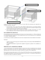
Two or more ranges can be batteried together to create larger lineups with fewer gas utility connections
and/or with continuous (overlapping) front top ledges and risers.
In battery lineups, it is recommended that the center range be installed and leveled first. Level each
range, one at a time, adjacent to the next.
CONNECTION
Each range with an oven or cabinet base is equipped with up to 4 attachment points to an adjacent unit.
Each modular (countertop) range is equipped with up to 2 attachment points. Additional attachment
means can be achieved when installing overlapping front top ledges, risers, banking strips, and
manifold plumb kits, available separately.
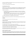
Each range is also supplied with a Battery Connection Kit. The kit comprises:
- 2X ¼-20 x 3” Bolts, with washers, nuts (for top)
- 1 Front Battery Bracket (for base)
- 1 Rear Battery Bracket (for base)
- 10X #10-24 x ½” Thread Cutting Screws (for brackets)
Strap Clamp
Backsplash
Channel

- 8 -
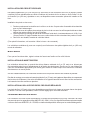
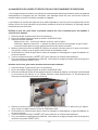
Install bolts and brackets as shown. Clamps may be used to pull the ranges together. Note:
1. For the ¼-20 x 3” bolts, first remove the knockouts in the side panels. This can be
accomplished by gently using a hammer to tap one of the bolts from the inside of the range
(knockout will fall outside of range).
2. For the Front Battery Bracket, the oven control panel and kick panel, if applicable, will first need
to be removed. Reinstall panels upon bracket installation.
MANIFOLD PLUMB
Manifolds can be batteried to form a common 1-1/4” rear pipe using manifold plumb kits, available
separately. The plumb kit also includes a port for connection to an overhead salamander or
cheesemelter.
Instructions for field manifold plumbing are provided separately with the manifold plumb kits.
Note:
• Check all gas connections for leaks. (See GAS CONNECTIONS in this manual.)
• The gas pressure regulator must have proper outlet pressure capacity for the battery
application.
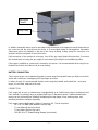
OVERLAPPING FRONT TOP LEDGE / RISER
All front top ledges and risers can be field removed and replaced with larger versions that overlap the
seam between adjacent ranges. Banking strips are also available to cover the seam between adjacent
open top burner sections.
¼-20 x 3” Bolts, Washers, Nuts
Rear Battery Bracket & Screws
Front Battery Bracket & Screws

- 9 -
Taller risers (10”, 22”, 34”) with solid shelves, flow-thru shelves, and reinforced risers for mounting
salamanders and cheesemelters are also available.
Instructions for field installation of overlapping front top ledges and risers are provided separately with
the accessory kits. Note: Shelves cannot be installed over charbroilers.
GAS CONNECTIONS
All gas supply connections and any pipe joint compound used must be resistant to the
action of propane gases.
An external gas pressure regulator must be installed by an authorized service technician before the unit
is placed into operation. The regulator must be listed by a nationally recognized testing agency and
suitable for the total range or battery capacity (see MANIFOLD PLUMB).
The pressure regulator must have a pressure adjustment range to allow adjustment to the manifold
pressure on the rating plate. Unless the manifold pressure on all connected appliances is the same, a
separate regulator must be supplied for each appliance having a differing manifold pressure.
HD Ranges are rated for the following pressures: Natural Gas: 6.0” water column (1.25 kPa), Propane
Gas: 10.0” water column (2.49 kPa). Pressure should be confirmed with all burners in operation and
using a manometer connected to one of the available pressure taps on the manifold.
Properly sized, preset gas pressure regulators for various pressure and capacity configurations are
available separately. The arrow on the regulator shows the direction of gas flow. The pressure regulator
must be mounted horizontally to ensure the leak limiter functions properly. A leak limiter is supplied with
every regulator to allow excess gas pressure to escape. Do not obstruct the limiter or the gas regulator,
as obstruction may cause the regulator to malfunction.
PRIOR TO LIGHTING, CHECK ALL JOINTS IN THE GAS SUPPLY LINE FOR
LEAKS. USE SOAP AND WATER SOLUTION. DO NOT USE AN OPEN FLAME.
A. CHECK ALL JOINTS PRIOR TO THE GAS VALVE (SOLENOID) BEFORE
LIGHTING UNIT.
B. CHECK ALL JOINTS BEYOND THE GAS VALVE (SOLENOID) AFTER
UNIT IS LIT.

- 10 -
After piping has been checked for leaks, all piping receiving gas should be fully purged to remove air.
TESTING THE GAS SUPPLY SYSTEM
When test pressures exceed ½ psig (14” w.c., 3.45 kPa), the range and its individual shutoff valve must
be disconnected from the gas supply piping system.
When test pressures are ½ psig (14” w.c., 3.45 kPa) or less, the range must be isolated from the gas
supply system by closing its individual manual shutoff valve.
FLUE CONNECTIONS
DO NOT obstruct the flow of flue gases from the flue located on the rear of the range. Proper venting of
flue gas is vital to the safe and efficient operation of the range. Problems arising from the intentional
obstruction of the flue will result in voiding of warranty. It is recommended that the flue gases be ventilated
to the outside of the building through a ventilation system installed by qualified personnel.
From the termination of the flue to the filters of the hood venting system, a minimum clearance of 18"
(457 mm) must be maintained.
Information on the construction and installation of ventilating hoods may be obtained from the standard
for "Vapor Removal from Cooking Equipment," NFPA No. 96 (latest edition), available from the National
Fire Protection Association, Batterymarch Park, Quincy, MA 02269.
ELECTRICAL CONNECTIONS
Electrical and grounding connections, when installed, must comply with local
codes, or in the absence of local codes, the National Electrical Code, NFPA 70, or the Canadian
Electrical Code, CSA C22.2, as applicable.
Disconnect the electrical power to the machine and follow Lockout / Tagout
procedures.
Appliances equipped with a flexible electrical supply cord are provided with a
three-prong grounding plug. It is imperative that this plug be connected into a properly grounded
three-prong receptacle. If the receptacle is not the proper grounding type, contact an electrician.
Do not remove the grounding prong from this plug.
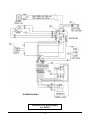
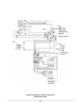
Do not connect the range to electrical supply until after gas connections have been made. Wiring
diagrams are available on the range (e.g. kick panel or rear of unit), the applicable service manual, and
this manual.

- 11 -
OPERATION
QUALIFIED PERSONNEL SHOULD PERFORM THE INITIAL FIELD START-UP AND
ADJUSTMENTS OF THE EQUIPMENT COVERED BY THIS MANUAL.
The appliance and its parts are hot. Use care when operating, cleaning, or
servicing the appliance.
BEFORE FIRST USE
Open Tops: Remove top grates from range top to carry out initial seasoning. Do not season the grates
while installed on the range top. Once grates are removed from range, apply a light coating
of liquid vegetable or spray-type cooking oil to each grate (seasoning process).
After seasoning, replace grates onto the range. Turn on all open top sections to LOW
and allow to burn for at least 15 minutes before using pots or pans on the range top.
Failure to season grates will cause grates to rust. Use of water and a wire or stiff brush
on the grate, followed by immediate drying before the next seasoning will help preserve
the cast iron color.
Ovens: New ovens require a burn off period to break in the oven and eliminate unappetizing odors
from penetrating the food product. Turn on gas to unit and set the thermostat to 475°F
(246°C). Allow the oven to operate at this temperature for 30 to 45 minutes.
Griddles/ Before leaving the factory the griddle is coated with food-grade lubricants as a rust
Planchas: inhibitor. Remove this film when the griddle plate is being cleaned prior to its first cooking
use. Heat the griddle to 200-300°F to loosen and melt the coating, then clean the surface
with a non-corrosive, grease-dissolving commercial cleaner, following the manufacturer’s
directions. Rinse thoroughly and wipe dry with a soft, clean cloth. Clean all accessories.
The griddle plate is steel, but the surface is soft and can be scored or
dented by careless use of spatulas or scrappers. Be careful not to dent, scratch
or gouge the plate. Do not try to knock off loose food that may be on the spatula
by tapping the corner edge of the spatula on the griddle surface.
Season the griddle to avoid possible surface corrosion before first use, and after every
cleaning. Heat griddle to a low temperature (300-350°F) and apply a small amount of
cooking oil – about one ounce per square foot of surface. Use a soft lint-free cloth to
spread the oil over the entire griddle surface to create a thin film. Wipe off any excess oil
with a cloth. Repeat the procedure until the griddle has a slick, mirror-like finish.
Charbroilers: The top grates are shipped flat (top-side down) from the factory. Remove the cast iron
grates and radiants. Inspect and remove the shipping restraints used during shipping to
hold the burners. Reassemble the radiants and top grates.
Allow the charbroiler to preheat for 30 minutes. Rub grates with cooking oil before
using.
French Tops: Install lava rocks under main castings. Season and clean similar to Open Top castings.

- 12 -
CONTROLS
Open Top Burner Valve — Allows gas to flow to the top burners. To open valve, turn knob
counterclockwise. To close valve, turn knob clockwise.
Manual Griddle, Hot Top Valve — Allows gas to flow to the griddle/hot top burners. To open valve, turn
knob counterclockwise. To close valve, turn knob clockwise. Turn the burner on full during burner ignition
then turn it back down to your desired setting once lit.
Griddle Thermostat — Snap-acting control with temperature range from LOW at approximately 200°F
(93°C) to HIGH at approximately 550°F (288°C). Note: Special Rapid Recovery Griddles have maximum
temperature of approximately 450°F (232°C).
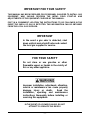
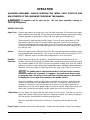
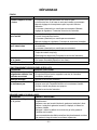
Oven Thermostat — Varies by oven type:
STANDARD OVEN: Combination snap-acting and modulating control with precise LOW control
at approximately 150°F (66°C) to HIGH control at approximately 550°F
(288°C).
FINISHING OVEN: Combination snap-acting and modulating control with precise LOW control
at approximately 400°F (204°C) to HIGH control at approximately 650°F
(343°C).
CONVECTION OVEN: Snap-acting control with temperature range from LOW at approximately
200°F (93°C) to HIGH at approximately 550°F (288°C).
Safety Valve – Monitors standing pilot. All ovens and select griddle and open top burner devices (Flame
Safety models) feature a standing pilot that is monitored by a thermocouple and pilot safety valve. If the
pilot goes out, the safety valve will shut-off the gas supply to the pilot and main burners.
Fan Switch – Turns fan on and off (Convection Ovens only). When cooking (“ON”), fan turns on when
door is closed and turns off when door is opened. In “COOL DOWN” mode, fan turns with door open or
closed. It is not possible to run a Convection oven with the fan off.
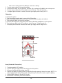
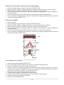
STANDARD / FINISHING
SAFETY
SHUT-OFF VALVE
THERMOSTAT
CONVECTION
SAFETY
THERMOSTAT
FAN SWITCH

- 13 -
LIGHTING PILOTS AND VERIFYING BURNER OPERATION
All burner configurations are equipped with standing pilots allowing for instant appliance use and low
maintenance. Lighting should be infrequent except during initial start-up or full appliance shut-down.
Pilot safety monitoring is standard on all ovens and is optional for open top burner and griddle devices
(Flame Safety models). Manual piezo ignition may be provided.
Open Top Burner, Griddle, and Hot Top (see next section for Flame Safety models)
1. Remove front row of grates (Open Top Only).
2. Turn the main gas supply valve to range to the ON position.
3. Light all standing pilots.
Open Top Burners - Pilot access can be reached under the grates.
Griddles/Hot Tops – Pilot access can be reached under the griddle plate through the slotted
opening in the manifold cover near the burner valve knob.
4. Turn the burner valve ON to ensure operation. Griddle/hot top burner visible thru front viewing port.
5. If burners fail to light, turn off all valves, and call an authorized installation or service person.
6. Turn the burner valve to the OFF position to shut off burner. Pilot will remain lit.
7. If complete pilot shut down is desired, turn main gas supply valve to range to OFF.
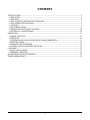
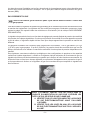
Open Top Burner, Griddle (Flame Safety models)
1. Remove front row of grates (Open Top Burners Only)
2. Turn the main gas supply valve to range to the ON position.
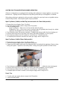
3. Depress and hold safety valve button and light pilot either conventionally by applying a flame or using
rotary piezo igniter. Repeat for each safety valve. Rotary piezo igniter operation is shown below.
4. Turn the burner valve ON to ensure operation. Griddle/hot top burner visible thru front viewing port.
5. If burners fail to light, turn off all valves, and call an authorized installation or service person.
6. Turn the burner valve to the OFF position to shut off burner. Pilot will remain lit.
7. If complete pilot shut down is desired, turn main gas supply valve to range to OFF
French Top
1. Turn the main gas supply valve to range to the ON position.
2. Light all standing pilots.

- 14 -
Pilot access can be reached by lifting the center two castings.
3. Turn the burner valve ON to ensure operation.
4. If burners fail to light, turn off all valves, and then call an authorized installation or service person.
5. Turn the burner valve to the OFF position to shut off burner. Pilot will remain lit.
6. If complete pilot shut down is desired, turn main gas supply valve to range to OFF.
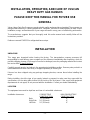
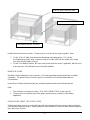
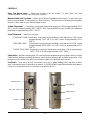
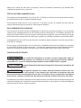
Charbroiler
1. Remove the grates.
2. Turn the main gas supply valve to range to the ON position.
3. Light all standing pilots. Pilot access can be reached under the grates and radiants.
4. Turn the burner valve ON to ensure operation.
5. If burners fail to light, turn off all valves, and call an authorized installation or service person.
6. Turn the burner valve to the OFF position to shut off burner. Pilot will remain lit.
7. If complete pilot shut down is desired, turn main gas supply valve to range to OFF.
Oven (Standard & Convection)
1. Turn thermostat to OFF position.
2. Turn the main gas supply valve to the range to the ON position.
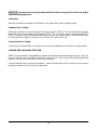
3. Lift up on the kick panel and rotate down 90°.
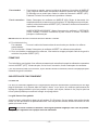
4. Depress red button on safety valve and light pilot through opening in burner box area. NOTE: For
ovens equipped with Rotary Piezo ignitor, rotary dial may be turned to create a spark for lighting.
5. Hold red button down for at least 30 seconds.
6. When button is released, pilot should remain lit.
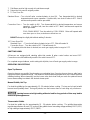
Grate
Radiant
Burner
Deflector

- 15 -
7. Pilot flame must be high enough to heat thermocouple.
8. Return the kick panel to original position.
9. To Turn Oven On:
Standard Oven – Turn shut-off valve counterclockwise to turn ON. Turn thermostat dial to desired
temperature and ensure operation. If ignition fails, turn shut-off valve to OFF. Wait 5
minutes and repeat the above procedure.
Convection Oven – Turn fan switch to ON. Turn thermostat dial to desired temperature and ensure
operation. If ignition fails, turn fan switch to OFF. Wait 5 minutes and repeat the
above procedure.
COOL-DOWN MODE: Turn fan switch to COOL DOWN. Motor will operate with
oven door open or close, main burner will not turn on.
DO NOT attempt to relight pilot without waiting 5 minutes.
10. To turn Oven Off:
Standard Oven – Turn shut-off valve clockwise to turn OFF. Pilot will remain lit.
Convection Oven – Turn fan switch to OFF. Pilot will remain lit.
11. If complete pilot shut down is desired, turn main gas supply valve to range to OFF.
SHUTTING DOWN
All burners are equipped with standing pilots that remain lit when control valves are turned OFF.
Convection ovens will additionally need the fan switch turned OFF.
For complete range shutdown, and to extinguish all pilots, turn off main gas supply valve to range.
OPERATING SUGGESTIONS
Open Top Burners
Open top burners are quickly lit and require no preheating time. Open top burners have a wide low to
high burner flame adjustment range. This allows for better simmering performance at the lowest possible
stabilized setting. When simmering, turn the burner valve knob down until you reach the optimum lowest
burner flame setting to maintain the desired simmer point.
Manual Griddle, Hot Top
Pre-heat the griddle top for approximately 15 - 20 minutes before cooking. The top can be kept hot with
burners turned partially down. During off periods, turn the burners down or heat using only one burner.
Leaving burners at a high setting without a load for long periods of time may lead to
undesired plate appearance.
Thermostatic Griddle
Pre-heat the griddle top for approximately 15 - 20 minutes before cooking. The griddle thermostats
regulate temperatures for each 12" section of the griddle from a low setting at approximately 200°F (93°C)
to high setting at approximately 550°F (288°C).

- 16 -
Leaving burners at a high setting without a load for long periods of time may lead to
undesired plate appearance.
Charbroiler
Allow the charbroiler to preheat for 30 minutes. Rub grates with cooking oil before using.
Standard Oven Cooking
Allow time to preheat ovens before using (25 minutes to 400°F [204°C]). The oven thermostat regulates
temperature from a low setting at approximately 250°F (121°C) to high setting at approximately 500°F
(260°C). If properly used, the automatic temperature control is an efficient system. Turn thermostat down
to LOW when oven is idling, or turn the oven control to OFF when not in use.
Convection Oven Cooking
Cooking time and temperature in convection oven may vary slightly from normal time and temperature.
LOADING AND UNLOADING THE OVEN
NOTE: It is the operator’s responsibility to protect skin surfaces before accessing the oven. Open the
door and load the oven as quickly as practical to conserve heat. Take care to avoid spilling liquids while
loading. Close the door and refer to recipe for cooking time.
Provide adequate space for product unloading. Rapid unloading will conserve heat and ensure proper
reheating conditions for the next load, if applicable.

- 17 -
CLEANING
Disconnect the electrical power to the machine and follow Lockout / Tagout
procedures.
Shut off the gas before cleaning the appliance.
The appliance and its parts are hot. Be very careful when operating, cleaning, or
servicing the appliance.
Exterior surfaces may be cleaned using soft cloth and mild detergent. Do not use highly chlorinated or
alkaline detergents to clean the exterior or interior components of the range, as these types of solutions
can lead to early degradation of the component.
Do not use scouring powder. It is extremely difficult to remove completely. It can build up accumulations
that will damage the oven.
Vulcan / Wolf equipment is strongly constructed and is designed to give you long, satisfactory service at
low cost, provided you give it proper care. Frequent cleaning and occasional adjusting should reward you
with low operating and maintenance costs and faster, better service.
REGULAR CLEANING
Open Top
Cast iron burner heads and grates are removable without use of tools. Clean cast iron open top burner
heads and grates with a mild soap and water solution. Rinse thoroughly and dry with a clean, water-
absorbent towel. Immediately after drying, season cast iron burners and grates lightly with liquid
vegetable or spray-type cooking oil.
After seasoning, replace cast iron parts onto the range. Turn on all open top sections to LOW and allow
them to burn for at least 15 minutes before using pots or pans on the range top. Season the cast iron
parts after each cleaning. Failure to season cast iron parts will cause grates to rust.
Burner heads and venturi must be kept clean and free of grease. Burner air shutter openings must be
kept clean.
Crumb trays, grate supports, and step-up burner boxes are removable without use of tools. Clean in
accordance with the Stainless Steel and General Cleaning guidance below.
Griddle Top
Clean the griddle regularly. A clean griddle looks better, lasts longer, and performs better. To produce
evenly cooked griddle products, keep the griddle plate clean and free of carbonized grease. Carbonized
grease on the surface hinders the transfer of heat from the griddle surface to the food, resulting in spotty
browning and loss of cooking efficiency. Carbonized grease tends to cling to griddle foods, giving them
a highly unsatisfactory and unappetizing appearance.
After each use, clean the griddle with a scouring pad or flexible spatula.
Once a day, thoroughly clean the griddle back splash, sides and front.

- 18 -
Griddle Grease Can
Empty grease can as needed throughout the day and regularly clean at least once daily. The grease
can has a weep hole to indicate that grease tray is full. Remove, empty and wash grease can in the
same manner as an ordinary cooking utensil.
In addition to grease can cleaning, inspect and clean grease can cavity weekly, or as needed. Once the
unit is cool, use an appropriate brush, towel, or cleaning device to ensure all visible surfaces are wiped
clean and that any buildup is removed from the cavity. This includes the cavity top and around the griddle
chute.
Service calls resulting from failure to properly empty the grease can or from maintaining a clean grease
can cavity will not be covered under warranty.
Charbroiler
Scrape top grates during broiling with a wire brush to keep the grates clean. Do not allow debris to
accumulate on the grates. Top grates may be immersed in strong commercial cleaning compound
overnight. In the morning, rinse with hot water to remove any residues of cleaning compound. Thoroughly
dry and apply cooking oil to prevent rusting. Places where fat, grease, or food can accumulate must be
cleaned regularly.
Never cover surface of unit with pans or other objects in attempt to “burn off” or clean
debris from unit. This will cause a buildup of heat that can damage and warp components of the
charbroiler.
Oven
Remove chrome-plated racks and clean in a sink. While still warm, wipe top with a soft cloth or other
grease absorbing material to remove spillovers, grease, etc., before they burn in. Clean oven and oven
door daily, especially if fruit pies or tomato sauces were baked, meats roasted, and if there have been
spillovers. After processing some foods at low temperatures, odors may linger in the oven. These odors
may be cleared by setting the thermostat at 500°F (260°C) and allowing the oven to operate unloaded
for 30 to 45 minutes.
EXTERIOR CLEANING
Daily
Clean exterior finish with a mild solution of soap or grease-dissolving cleaner. To remove discoloration,
use a nonabrasive cleaner. Always rub with the grain of the metal. Stainless steel areas of the range can
be polished by using a soft dry cloth. If needed, add stainless steel polish to the soft cloth.
Stainless Steel
Here are a few simple cleaning procedures that have been found effective for keeping stainless steel
equipment clean, sparkling and bright.
General Cleaning

- 19 -
Use ordinary soap or detergent and water for routine cleaning of stainless steel. To prevent water spots
and streaks, rinse thoroughly with warm water and wipe dry with a soft clean cloth. The addition of a
rinsing agent will also help prevent spotting. Do not pressure wash any portion of the range.
Fingerprints
Fingerprints are sometimes a problem on highly polished surfaces of stainless steel. They can be
minimized by applying a cleaner that will leave a thin oily or waxy film. To use these cleaners, simply
wipe on and remove excess with a soft dry cloth. After using, subsequent fingerprints will usually
disappear when wiped lightly with a soft cloth or with a cloth containing a little of the cleaner. If the surface
is especially dirty to start, wash first with soap or detergent and water.
Heat Tint
Straw-colored or slightly darkened areas may appear on stainless steel in and around ovens and ranges
where temperatures reach 500°F (260°C) or more. This "heat tint" is caused by a slight oxidation of the
stainless steel and is not harmful. To control or minimize this condition, never use more heat than is
absolutely necessary.

- 20 -
MAINTENANCE & ADJUSTMENTS
Disconnect the electrical power to the machine and follow Lockout / Tagout
procedures.
LUBRICATION
All moving parts must be checked for wear and lubricated. Contact your local authorized servicer. Motors
in Vulcan Endurance / Wolf Challenger convection ranges are permanently lubricated and require no
additional maintenance.
FLUE
Check the flue when it is cool to be sure it is free of obstructions.
SERVICE AND PARTS INFORMATION
To obtain service and parts information, contact an authorized service agency in your area (refer to our
website, www.vulcanequipment.com or www.wolfequipment.com for a complete listing of authorized
service and parts depots). When calling for service, the following information must be available: model
number, serial number, and gas type. This information can be found on the main data plate, located on
the rear of the unit, or on the secondary plate located inside the lower front kick panel. Lift up and lower
the front kick panel to view the secondary data plate.
PRECAUTIONS
When scraping off heavy deposits of grease or oil from stainless steel equipment, never use ordinary
steel scrapers. Particles of ordinary steel may become embedded in, or lodge on, the surface of the
stainless steel. These will rust, causing unsightly stains and possible contamination of food. If it is
necessary to scrape, use stainless steel, wood, plastic or rubber tools.
La page charge ...
La page charge ...
La page charge ...
La page charge ...
La page charge ...
La page charge ...
La page charge ...
La page charge ...
La page charge ...
La page charge ...
La page charge ...
La page charge ...
La page charge ...
La page charge ...
La page charge ...
La page charge ...
La page charge ...
La page charge ...
La page charge ...
La page charge ...
La page charge ...
La page charge ...
La page charge ...
La page charge ...
-
 1
1
-
 2
2
-
 3
3
-
 4
4
-
 5
5
-
 6
6
-
 7
7
-
 8
8
-
 9
9
-
 10
10
-
 11
11
-
 12
12
-
 13
13
-
 14
14
-
 15
15
-
 16
16
-
 17
17
-
 18
18
-
 19
19
-
 20
20
-
 21
21
-
 22
22
-
 23
23
-
 24
24
-
 25
25
-
 26
26
-
 27
27
-
 28
28
-
 29
29
-
 30
30
-
 31
31
-
 32
32
-
 33
33
-
 34
34
-
 35
35
-
 36
36
-
 37
37
-
 38
38
-
 39
39
-
 40
40
-
 41
41
-
 42
42
-
 43
43
-
 44
44


Vulcan HD Series Range Mode d'emploi
- Catégorie
- Cheminées
- Taper
- Mode d'emploi