Porter & Charles FEC60B(x) Manuel utilisateur
- Taper
- Manuel utilisateur

USER’S MANUAL
FEC60B(x)
FEC76B(x)
FEC90B(x)
FEG60(x)
FEG76(x)
FEG90(x)

2
Congratulations on the purchase of your
Porter&Charles
appliance.
We are sure it will provide many years of great cooking experience.
You may find that it has different features and characteristics to your last
appliance.
It is essential you read this operation manual thoroughly to fully
understand all of the various functions and operations. Experiment with
your cooking and take advantage of the features your new appliance offers.
This manual should be retained for future reference. Should ownership of
the appliance be transferred, please ensure that the manual is also passed
onto the new owner.
Contents
A - Installation check and warnings Page 3 - 7
B - Range Measurements Page 8 - 11
C - Electrical Requirements Page 12
D- Using the appliance for the first time Page 13 - 14
E- Accessories Page 14- 15
F- Electronic Programmer Operation Page 16 - 18
G- Gas Cooktop Control Panel Page 19
H- Gas Cooktop Control Functions Page 20
I- Ceramic Cooktop Control Panel Page 21 - 22
L- Ceramic Cooktop Functions Page 23
M- Oven Functions & Control Panel Page 24 - 30
N- Cleaning and maintenance Page 31 - 35
P- Trouble shooting guide Page 35
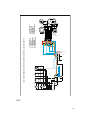
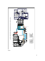
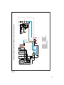
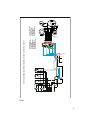
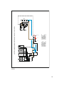
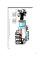
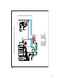
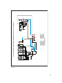
Wiring diagram Page 36-41
Q- Warranty Page 42

3
A - Installation instructions check and warnings
WARNING
This appliance is not intended for use by persons (including children) with reduced
physical, sensory or mental capabilities, or lack of experience and knowledge, unless they
have been given supervision or instruction concerning use of the appliance by a person
responsible for their safety.
Children should be supervised to ensure that they do not play with the appliance.
WARNING
During use the appliance becomes hot. Care should be taken to avoid touching heating elements
inside the oven.
IMPORTANT:
Please ensure that the cut out measurement, venting and wiring is as specified in the
relevant section B of this manual.
A licensed electrician with relevant qualifications must perform electrical work when installing or
servicing the appliance. The supply cable and fuse rating must be suitable for the appliance. You
must never repair or replace any part of the appliance unless specifically recommended in the
operation manual.
Ventilation opening must not be covered or obstructed in any way.
VENTILATION
The room containing this range should have an air supply in accordance with local regulations.
- All rooms require an open window, or equivalent and some rooms will require a
permanent vent also.
- For room areas up to 5m
2
an air vent of 100cm
2
is required.
- For room areas between 5m
2
and 100cm
2
an air vent of 50cm
2
is required.
- If the room is greater than 5m
2
and has a door that opens directly to the outside, then no
air vent is required.
- If there are other fuel burning appliances in the same room, check your local regulations
to determine the air vent requirements.

4
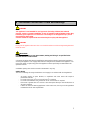
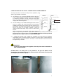
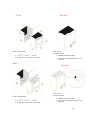
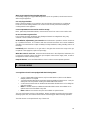
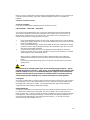
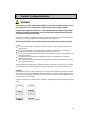
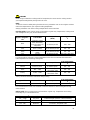
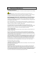
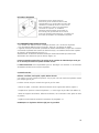
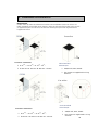
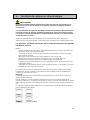
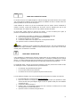
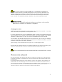
DISCHARGE OF FUEL GASES
Cooking appliances must always discharge the flue
gases into special hoods (fig.1-C), which must be
connected to chimneys, flue pipes or have direct
access to the outside. If it is not possible to connect
a hood, an electric fan can be fitted to a window or
a wall (fig.1-E), which must be turned on when the
cooker is on, as long as ventilation standards are
strictly adhered to.
Fig.1
RECOMMENDED VENTILATION HEIGHT
- for ceramic cooktop model min. 60cm (24”) above range
- for gas cooktop model min. 76cm (30”) above range
When ranges are installed in close proximity to vinyl finish cabinets, those materials should be
able to withstand temperatures up to 75°C.
Alternatively, heat insulating barriers should be installed to avoid any deterioration to the
finish.
The equipment must not be installed near inflammable materials, such as curtains, cloths, etc.
Pay particular attention to the position of the electric cable and gas pipe: they must
not touch any hot parts of the oven.
The manufacturer will not accept responsibility for damages to cabinetry where
manufacturer’s installation guidelines were not adhered to.
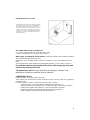
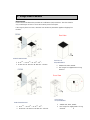
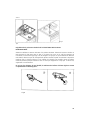
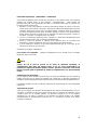
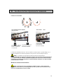
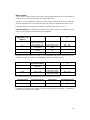
CONVERTING TO LPG
Burners: auxiliary, semi-rapid, rapid, wok burner.
These burners are all fitted with injectors designed to create a primary input of air gauged for
each type of gas.
Proceed as follows in order to convert from one type of gas to another:
- remove the grids, covers, flame diffuser and the burner supports (fig. 7);
- replace the injectors as indicated in 7/C according to the type of gas used (see table 1);
- put the burner supports, flame diffusers, covers and grids back in position;
- regulate the minimum output following the instructions in paragraph 1.7.
NOTE: Regulator needs to be set for the gas being used.

5
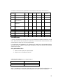
Table 1
Fig.7
7/C
REGULATING THE MINIMUM OUTPUT OF THE COOKTOP BURNERS
Normal/valve taps:
Ignite the burners and turn the knob to the minimum position. Remove the knob and insert a small
flat-head screwdriver into the rod or through the holes on the side of the control panel, in
accordance with the type (fig. 8 A/B). Adjust the screw until the flame is lowered but stable, even
when rapid changes are made from the maximum to the minimum position with the burner cold. If
safety taps are fitted, let the burner run on minimum for a few minutes to ensure that the device
does not cut in. If it does, increase the minimum.
N.B. For liquid gas settings, the burner minimum must be set by fully tightening the tap
by-passes.
Fig.8

6
WARNINGS:
- Using a gas cooktop produces heat and humidity in the room where it is installed. Ensure the
room is well ventilated by keeping all the natural air vents open or by installing an extraction
hood with flue pipe.
- Intensive or extensive use of the range may require supplementary ventilation e.g. opening a
window, or more efficient ventilation e.g. increasing the capacity of the mechanical
ventilation, if installed.
- If the burner flames accidentally go out due to excessive airflow, turn off the KNOB and wait
for at least one minute before igniting.
N.B. When the burners are alight, there must not be any draughts inside the room
in that they may affect the flame or even blow it out.
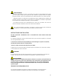
INSTALLATION INSTRUCTIONS
DO NOT LIFT RANGE BY THE FRONT DOOR HANDLE AS THIS WILL DAMAGE THE UNIT.
The operations indicated below must be followed by a qualified technician, in compliance with
local regulations.
The supplier refuses all responsibility for damages to person or property, resulting from
the failure to comply with such provisions.
All units are 208/240Volt power and 60Hz.
The appliance is designed to be used near heat resistant pieces of furniture or kitchen cabinetry
only.
ATTENTION
Disregard of this precaution could cause the incorrect operation of the touch control system of the
cooktop and affect the product warranty provisions.
WARNING:
All aspects of the installation must conform to North American wiring standards, as well
as your local electrical and building codes and regulations, and any other applicable
requirements and conditions of your local power supply authority. Your appliance must be
properly installed and grounded by a qualified and licensed technician.
208/240Volt 60 Hz 30Amp/40Amp service
Incorrect installation of the appliance, resulting from the installer not following the detailed
installation specifications, can affect the performance of the appliance.

7
CONNECTION TO THE GAS SUPPLY: CURRENT INSTALLATION STANDARDS
The range should be connected according to local regulations, using
either a rigid or flexible connections.
a) For building in: Use a continuous flexible stainless steel pipe,
as per current installation standards, which can be extended
to a maximum of 2000mm.; the ends of the pipe must be fitted
with an ISO 228/1coupling and gasket or an ISO 7/1 threaded
coupling with mechanical gasket.
b) For free standing: A non-metallic flexible pipe can be used as
long as it complies with current standards and the following
installation instructions are observed: the pipe must be longer
than 400mm and shorter than 1500mm; it must not exceed
50°C at any point; it is not pulled or twisted; it cannot be
choked and the entire edges, sharp corners or other similar
hazards.
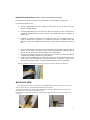
Before connecting the non-metallic flexible pipe, the brass
adapter and gasket supplied with the range and/or available from the reseller must be fitted to
the pipe/gas train on the back of the range. The regulator provided should be positioned
between the brass adapter and the non metallic flexible pipe.
c) A certified gas plumber must complete the installation and meet with local regulation
requirements for gas connections. Where the unit has an armour cable a certified electrician
must complete the electrical connection. The white, or neutral wire will not be used and must
be capped using a marrette.
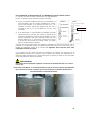
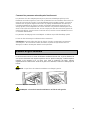
WARNINGS:
In order to prevent tipping of the appliance, the safety chain must be attached to a
hook secured to the wall.
(PLEASE NOTE: The fixing hook is not provided as the type will depend on the
construction of the wall to which it will be drilled and fitted. The installer should provide
the fixing hook per customer request).
Washer inside brass adaptor
Brass Adaptor
Show the regulator.…

8
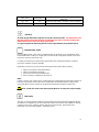
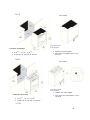
B - Range Measurements
Measurements
Please note that all dimensions provided are in millimeters (mm) and inches. The sizes allow for
only a small degree of error so all cut-outs must be precise and square.
If the range is placed on a base, measures have to taken to prevent the appliance slipping from
the base.
FEC60 Rear View
•
D: 25
3/16
” • W: 23
5/8
” • H: 33
7/8
” - 36
1/4
”
•
D: 640 mm • W: 600 mm • W: 860 mm – 920 mm
RANGE DIMENSIONS
•
208/240 Volt, 60Hz, 40AMP
•
P&C ranges are supplied with a 5’ long
electrical.
ELECTRICAL
REQUIREMENTS
•
D: 25
3/16
” • W: 23
5/8
” • H: 33
7/8
” - 36
1/4
”
•
D: 640 mm • W: 600 mm • W: 860 mm – 920 mm
RANGE DIMENSIONS
•
208/240 Volt, 60Hz, 40AMP
•
P&C ranges are supplied with a 5’ long
electrical.
ELECTRICAL
REQUIREMENTS
FEG60
Rear
View

9
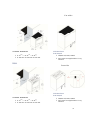
FEC76
FEG76
Rear View
Rear View
•
D: 25
3/16
” • W: 30” • H: 36
1/4
”
•
D: 640 mm • W: 762 mm • W: 920 mm
RANGE DIMENSIONS
•
208/240 Volt, 60Hz, 40AMP
•
P&C ranges are supplied with a 5’ long
electrical.
ELECTRICAL
REQUIREMENTS
•
D: 25
3/16
” • W: 30” • H: 36
1/4
”
•
D: 640 mm • W: 762 mm • W: 920 mm
RANGE DIMENSIONS
•
208/240 Volt, 60Hz, 40AMP
•
P&C ranges are supplied with a 5’ long
electrical.
ELECTRICAL
REQUIREME
NTS

10
FEC90 Rear View
FEG90
Rear View
•
D: 25
3/16
” • W: 35
7/16
” • H: 36
1/4
”
•
D: 640 mm • W: 900 mm • W: 920 mm
RANGE DIMENSIONS
•
208/240 Volt, 60Hz, 40AMP
•
P&C ranges are supplied with a 5’ long
electrical.
ELECTRICAL
REQUIREMENTS
•
D: 25
3/16
” • W: 35
7/16
” • H: 36
1/4
”
•
D: 640 mm • W: 900 mm • W: 920 mm
RANGE DIMENSIONS
•
208/240 Volt, 60Hz, 40AMP
•
P&C ranges are supplied with a 5’ long
electrical.
ELECTRICAL
REQUIREMENTS

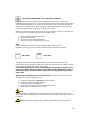
11
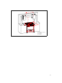
C
D
A
B
C
A= same dimension of appliance
B= 30" ( 762mm)
C= 4,5" (110mm)
D= 8,1"(200mm)

12
C – Electrical requirements
WARNING:
All aspects of the installation must conform to the requirements of the standard North
American wiring rules, as well as your local electrical and building codes and regulations,
and any other applicable requirements and conditions of your local power supply
authority. A licensed electrician must perform the electrical work when installing this
appliance. The supply cable and fuse rating must be suitable for the appliance. The range
is supplied with a 40AMP corded plug.
240Volt 60Hz 40AMP (range with ceramic cooktop)
240Volt 60Hz 30AMP (range with gas cooktop)
Note:
To the electrician – please ensure sufficient supply cable is provided to allow the appliance to be
removed from the cavity should any servicing be necessary. This will also allow easy connection
of the supply.
Voltage supply connection, if unit not supplied with power cord
To connect the electrical supply:
1- This appliance must be installed individually on a separate and distinct final sub-circuit.
2- Ensure the supply cable and fuse rating are suitable for the appliance (see the electrical
loading).
3- Remove the cover plate by undoing the screw.
4- Fit a suitable entry bush to the conduit entry on the rear left of the appliance (with the rear
toward you) and feed the fixed wiring through.
5- Connect the wiring to the terminal block using the screw connections provided. Ensure
the wires are properly secured to prevent any high resistance electrical connection.
6- Replace the cover plate making certain that the supply wiring is clear of any metal work
and the screws.
7- If the supply cord is damaged, it must be replaced by the manufacturer, its service agent
or similarly qualified persons in order to avoid hazard
When connected to a sub circuit, protected by a circuit breaker, it is recommended the circuit
breaker be the same as the total rating of the appliance.
To fully disconnect the power supply, it is necessary to have a proper mean in the fixed
wiring in accordance with the wiring rules. It must have full disconnection under
overvoltage category III conditions.
If you wish a direct connection to the line, it is necessary to use a double pole switch, with a
minimum opening between the contacts of 3mm. suitable for the purpose and in compliance with
local regulations (the green ground cable should not be interrupted by the switch).

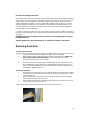
13
D – Using the appliance for the first time
After installation remove all notification labels (not identification or warning labels) and packaging
materials. After cleaning make sure cleaned surfaces are thoroughly rinsed and wiped dry using a
clean, soft cloth.
Power on
NOTE: Oven will not operate unless the clock is set.
When power is first applied the display will flash and shows 00:00.
The time of day is displayed in digital 24 hour format (e.g.: 18:00 is 6:00 pm).
Burning in
Before cooking in the appliance an initial pre-heating is required to burn off the fine oil film used to
protect the elements for shipping. Select a cooking mode and set the oven temperature to 180°C.
With the oven door closed, leave for approximately 5 minutes.
Repeat the above step for each cooking mode.
After completing the above make sure all controls are turned off. The oven is now ready for
cooking and grilling.
DO NOT use aluminum foil on the base of ovens
The use of foil on the base of the oven to avoid spillage and improve cleaning is not
recommended. The bottom element is concealed under the base of the oven liner (not exposed).
Foil or dishes with reflective qualities must never be placed on the base of the oven during
cooking as the concentration of direct and reflected heat will damage the enamel surface.
WARNING
Damage resulting from such use is not covered under the provisions of the warranty.
Initial heat up
Some smoke and smell may be noticed during the initial heat up cycle. This is normal and should
quickly dissipate. If abnormal levels of smoke occur during use (i.e.: it is not food that is burning),
have the appliance thoroughly checked.
Don’t use the appliance as a space heater
The appliance must never be used for warming or heating the surrounding room. Combustible
materials must never be placed on or near the appliance.
Do not leave children alone
Children must not be left unsupervised in the area where the appliance is in use. Children must
never be allowed to sit or stand on any part of the appliance.

14
Wear proper apparel when using the appliance
Loose fitting, hanging or highly flammable garments (such as synthetics) should never be worn
while using the appliance.
Use only dry pot holders
Moist or damp pot holders on hot surfaces may result in burns from steam. Do not allow pot
holder to touch hot heating elements. Do not use a towel or bulky cloth when handling hot
cooking utensils in the appliance.
Oven compartments must never be used for storage
Items, particularly flammable materials, must never be stored in an oven or near surface units.
Do not use water on grease fires
Fires or flame should be smothered using flameproof material or extinguished using a dry
chemical or other suitable fire retardant.
All installation, adjustments, gas-conversion and maintenance operations must be carried out
by a qualified technician, in accordance with the enclosed instructions and current installation
standards. The manufacturer accepts no liability for faulty installation, setting, handling and use of
the range.
Periodically check that there are no gas leaks in the pipe that connects the range to the gas
receptacle or the supply line; replace it upon expiry.
When the cooker is not in use, ensure that all the knobs are in the off position; furthermore, if it
is unused for a period of time, shut off the gas receptacle valve and the supply valve, as well as
the appliance’s mains electricity supply.
Keep the burners, covers and flame diffusers clean in order to ensure optimum operation
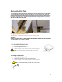
E - Accessories
Your appliance should come equipped with the following items.
• 1 x pair of Retractable Slide Runners( only for model 76/90cm.) which can be fitted to
multiple positions as required
• 1 x Deep Enameled Roasting Pan with dual height reversible Grill Rack insert – ready for
sliding into side rack positions or fitting onto Retractable Slide Runners
• 2 x Wire Oven Shelves that can be fitted into Retractable Slide Runners or for sliding into
side rack positions
• Note: For models 76/90cm. Additional Retractable Slide Runners are available as an
optional extra and can be fitted at any time
• Note: Additional oven shelves and pans are available as optional extras.
The oven shelf support consists of 5/6 positions. Always remember to position the racks before
warming up the oven, and remove all the shelves and roasting pan before cleaning operations.
The slide runners can be positioned in any of the 6 rails

15
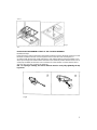
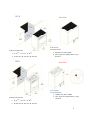
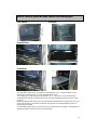
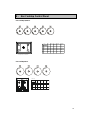
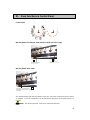
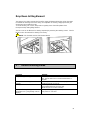
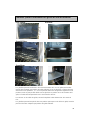
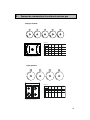
How to correctly place the oven shelves and roasting pan
Oven 76/90cm Oven 60cm.
1
2
3
4
5
6
Oven 60/76cm.
Oven 90cm.
The retractable slide runners can operate on shelf positions 2 to 6. The wire shelves can be
inserted at any shelf position, or on the retractable slide runner.
The roasting pan can be inserted on shelf positions 1, 2, 3, 4 and 5. It can be used with the
retractable slide runners for shelf position 6, but cannot be used with the slide runners for shelf
position 4.
When inserting the wire shelf, the riser should be positioned upwards at the rear of the oven. The
grooves at the sides of the shelves, toward the rear provide an anti-slide stability for the oven
shelves when extended.
The retractable slide runners can be inserted on any shelf position by clipping or unclipping them
between the upper and lower rail of each shelf position

16
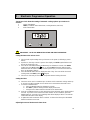
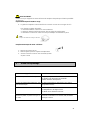
F - Electronic Programmer Operation
The 24 hour clock allows the setting of automatic cooking options up to 24 hours in
advance.
1 - Minus Time Button
2 Mode (Countdown Timer with Alarm, Cooking duration, End Time)
3 + Plus Time Button
IMPORTANT – NOTE FOR NEW INSTALLATION AND FIRST OPERATION
Setting the time on the 24 hour clock
1- The clock will require setting when you first turn on the power (or following a power
failure).
2- At power on, the relay contact is opened. The display and AUTO symbol flashes and
time of day starts from 0:00.
3- Press PLUS and MINUS button simultaneously for minimum 3 seconds. The AUTO
symbol goes out, POT symbol goes on, and the DOT is flashing. With the PLUS
button the time will advance slowly, and then speed up. If you over-shoot the desired
time, use the MINUS button).
4- Press the MODE button twice to display the time of day. The oven will be in manual
cooking mode, with POT symbol displayed.
5- The oven is now ready for use and to accept the selected cooking functions.
Setting the Timer
6- The timer can be set for countdown up to 24 hours and for automatic cooking modes up
to 10 hours and will countdown to zero. When zero is reached the alarm will sound.
7- To set the countdown timer
a. Press the MODE button for minimum 3 seconds.
b. The BELL symbol is flashing and the display shows 0:00.
c. Using the PLUS button advance the timer to the desired time.
8- Once the countdown timer is set, the normal time of day will return to the display within 7
seconds. If you wish to check how much time remains on the countdown, press the
MODE button for 3 seconds. The remaining time will be displayed. After 7 seconds the
normal time will return to the display.
9- A digital alarm will sound when time is reached. To silence the alarm press the MODE
button for minimum 4 seconds.
Adjusting the tone of the electronic timer alarm.

17
THE TONE
There are 3 different tones from which you can select. To change the tone you press the “+” and
“-“ simultaneously, then press the Mode button once, ton will be displayed. Pressing the “-“ button
while ton is in the display, will change the tone to the desired setting, then press the mode button
once. The electronic timer will store in its memory the last tone activated.
Manual cooking
Once the time of day is set the POT symbol will be displayed. The oven is now in
manual operation mode ready for you to select the desired cooking function and
temperature.
Automatic cooking modes – Based on setting the duration “DUR”
1 Set cooking function and temperature to the desired position.
2 For example: If you wish to cook for 45 minutes, press the MODE button minimum for 4
seconds. Press the MODE button again. The AUTO symbol is flashing and the display
shows “dur”. The display automatically switches over between "dur" display and 0:00.
During this time you can set the duration time of 45 minutes by pressing the PLUS button
(use MINUS button should you over-shoot the required time). Release and the display
will return to the normal time of day after 7 seconds. The AUTO symbol will also appear
indicating that you have set the automatic cooking function.
3 The oven will operate for 45 minutes only, turn off automatically and the alarm will sound.
The AUTO symbol is flashing and the POT symbol will disappear. The alarm will turn off
after pressing the MODE button. If you hold the MODE button down longer than 4
seconds the oven will return to the normal cooking mode.
4 If further cooking is required, either leave on manual or repeat the above setting
sequence.
Note: If you have not turned the cooking function and temperature setting off, your oven will now
continue to operate manually. The AUTO symbol will disappear and the POT symbol will
reappear.
Automatic cooking modes – Based on setting a cook end time
1 Set the function and thermostat control to the desired position.
2 For example: If you would like the oven to turn off at 6.00pm, press the MODE button
minimum for 4 seconds. Display shows 00:00 with BELL flashing. Press the MODE
button two times again. The AUTO symbol is flashing and the display shows “End”. The
display automatically switches over between "End" and time of day. During this time you
can set the cooking stop time to 6.00pm, i.e.18:00 on the 24 hour clock, by pressing the
PLUS button (use MINUS button should you over-shoot the required time). Release and
the display will return to the normal time of day after 7 seconds. The AUTO symbol will
also appear indicating that you have set the automatic cooking function.
3 The oven will continue to cook until 18:00 (6.00pm) and then switch off and the alarm will
sound. The AUTO symbol is flashing and the POT symbol will disappear. The alarm will
turn off after pressing the MODE button.
4 If you hold the MODE button pressed longer then 4 seconds the oven will return to the
normal cooking mode.
5 If further cooking is required, either leave on manual or repeat the above setting
sequence.

18
Note: If you have not turned the cooking function and temperature setting off, your oven will now
continue to operate manually. The AUTO symbol will disappear and the POT symbol will
reappear.
C
ANCELING AUTOMATIC SETTINGS
To cancel a program:
Press plus and minus button simultaneously for minimum 3 seconds.
Fully automatic – (Start Later – Stop Later)
Your oven may be programmed to start, cook for the desired time and turn off automatically.
This function is particularly useful in the preparation of the evening meal, should you be out
during the day, it will be ready on your return home. For example, if your cooking time is 45
minutes and you want the cooking to finish at 6.00 p.m.
1 Press the MODE button minimum for 4 seconds, display shows 00:00. Press the MODE
button again, display shows DUR. Set the cooking duration time for say 45 minutes using
the PLUS or MINUS button.
2 Press the MODE button again, display shows END. Set the stop cooking time to 6.00pm
(18:00hrs). Release and the display will return to the normal time of day after 7 seconds.
The AUTO symbol will be displayed.
3 Using the above settings, the oven is now programmed automatically to commence
cooking 45 minutes prior to 6.00 pm (18:00hrs). The AUTO symbol and the POT symbol
will be displayed. Then automatically turn off.
When cooking is complete the AUTO symbol is flashing and the POT symbol will
disappear and the alarm will sound. The alarm will turn off after pressing the MODE
button.
4 If you hold the MODE button longer then 4 seconds the oven will return to the normal
cooking mode.
NOTE:
On oven start up or possibly at other times, due to electricity supply deviations – the set
program may freeze on a function – if this occurs we recommend that, after checking other
solutions without success, it is recommended that power supply be disconnected to the
appliance and allow it to be in this position for 5 minutes before reconnecting. This may
clear the frozen position allowing you to reset the clock/timer for normal operation.
Cooling Fan
The oven is provided with a cooling fan motor to reduce the heat around the oven. The fan motor
is controlled by a sensor, which will start when the oven is switched on and stop working when
the temperature is reduced accordingly. This safeguards both the range and the adjoining
cupboards from the possibility of temperature damage.
Safety Thermostat
Your range is fitted with an over-temperature sensor that will automatically shut down your oven
for a period if it is deemed to be overheating- this sensor is fitted to the rear wall of the oven,
inside the outer case – it will only activate in extreme circumstances and is provided as protection
to the appliance and the adjoining furnishings. If activated it will shut down the appliance for a
short time and will automatically reset allowing normal operation – you should consult your
service technician if the problem re-occurs.

19
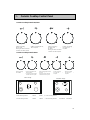
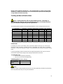
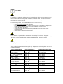
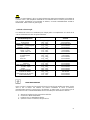
G - Gas Cooktop Control Panel
Gas cooktop 76/90cm.
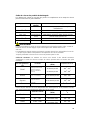
Technical Characteristic table
NOMINAL
HEAT INPUT
MAX.
(bTU/H)
INJECTOR
DIAMETER
1/100 mm
TAP BY PASS
DIAMETER
1/100mm
BURNERS
N° DESCRIPTION
GAS NORMAL
PRESSURE
mbar
2 RAPID
PROPANE 28 115 65 17.500
NATURAL 10 200 REG. 15.600
PROPANE 28 72 35 8.000
NATURAL 10 118 REG. 8.000
PROPANE 28 90 46 11.300
NATURAL 10 155 REG. 11.500
PROPANE 28 55 35 5.000
NATURAL 10 90 REG. 5.000
3 AUXILIARY
4 WOK
1 SEMI-RAPID
Gas cooktop 60cm.
21
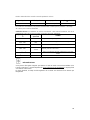
43
1= bruleur semirapid 2= bruleur rapid
3=bruleur auxiliary 4= bruleur wok
Details techniques
puissance
nominale
MAX.
(bT U/H)
INJECteurs
DIAMET ER
1/100 mm
Rob inet BY PASS
DIAM ETER
1/100m m
Bruleurs
N° DESCRIPTION
GAS Pression
normale
mbar
2 RAPID
PROPANE 28 115 65 17.500
NA TURAL 10 200 REG. 15.600
PROPANE 28 72 35 8.000
NA TURAL 10 118 REG. 8.000
PROPANE 28 90 46 11.300
NA TURAL 10 155 REG. 11.500
PROPANE 28 55 35 5.000
NA TURAL 10 90 REG. 5.000
3 AUXILIARY
4 WOK
1 SEMI-RAPID
1= semirapid burner 2= rapid burner
3=auxiliary burner 4= wok burner
1
2
3
4
1

20
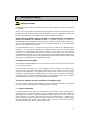
H - Gas Cooktop Functions
B - Cooking Instructions
Automatic start-up with valves
Turn the corresponding knob anticlockwise up to the maximum position and press the knob.
Once the burner has been started up, keep the knob pressed for about 6 seconds.
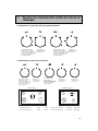
Using the burners
In order to obtain the maximum yield without wasting gas, it is important that the diameter of the
pot is suitable for the burner potential (see the following table and fig.1). This is to avoid the flame
extremities being larger than the base of the pot. All of the operating positions must be chosen
between the high and the low settings, never between the high position and the closing point.
The gas supply can be interrupted by turning the knob clockwise up to the off position.
NOTE:
When the equipment is switched off, always check that the knobs are in the off position.
NOTE:
If there is no power supply, it is possible to light the burners with matches, setting the knob to the
high setting.
NOTE:
If the flame should blow out accidentally, the safety valve will automatically stop the gas supply,
after 20 - 30 seconds. To restore operation, turn the knob to the off position.
WARNING:
-Do not use sprays near the appliance in operation.
-Do not place unstable pots on the burner to prevent them from tipping or overflowing.
-Always turn gas off if moving a pot away from the appliance.
-While cooking with fat or oil, pay the utmost attention as these substances can catch fire when
overheated.
La page est en cours de chargement...
La page est en cours de chargement...
La page est en cours de chargement...
La page est en cours de chargement...
La page est en cours de chargement...
La page est en cours de chargement...
La page est en cours de chargement...
La page est en cours de chargement...
La page est en cours de chargement...
La page est en cours de chargement...
La page est en cours de chargement...
La page est en cours de chargement...
La page est en cours de chargement...
La page est en cours de chargement...
La page est en cours de chargement...
La page est en cours de chargement...
La page est en cours de chargement...
La page est en cours de chargement...
La page est en cours de chargement...
La page est en cours de chargement...
La page est en cours de chargement...
La page est en cours de chargement...
La page est en cours de chargement...
La page est en cours de chargement...
La page est en cours de chargement...
La page est en cours de chargement...
La page est en cours de chargement...
La page est en cours de chargement...
La page est en cours de chargement...
La page est en cours de chargement...
La page est en cours de chargement...
La page est en cours de chargement...
La page est en cours de chargement...
La page est en cours de chargement...
La page est en cours de chargement...
La page est en cours de chargement...
La page est en cours de chargement...
La page est en cours de chargement...
La page est en cours de chargement...
La page est en cours de chargement...
La page est en cours de chargement...
La page est en cours de chargement...
La page est en cours de chargement...
La page est en cours de chargement...
La page est en cours de chargement...
La page est en cours de chargement...
La page est en cours de chargement...
La page est en cours de chargement...
La page est en cours de chargement...
La page est en cours de chargement...
La page est en cours de chargement...
La page est en cours de chargement...
La page est en cours de chargement...
La page est en cours de chargement...
La page est en cours de chargement...
La page est en cours de chargement...
La page est en cours de chargement...
La page est en cours de chargement...
La page est en cours de chargement...
La page est en cours de chargement...
La page est en cours de chargement...
La page est en cours de chargement...
La page est en cours de chargement...
La page est en cours de chargement...
La page est en cours de chargement...
-
 1
1
-
 2
2
-
 3
3
-
 4
4
-
 5
5
-
 6
6
-
 7
7
-
 8
8
-
 9
9
-
 10
10
-
 11
11
-
 12
12
-
 13
13
-
 14
14
-
 15
15
-
 16
16
-
 17
17
-
 18
18
-
 19
19
-
 20
20
-
 21
21
-
 22
22
-
 23
23
-
 24
24
-
 25
25
-
 26
26
-
 27
27
-
 28
28
-
 29
29
-
 30
30
-
 31
31
-
 32
32
-
 33
33
-
 34
34
-
 35
35
-
 36
36
-
 37
37
-
 38
38
-
 39
39
-
 40
40
-
 41
41
-
 42
42
-
 43
43
-
 44
44
-
 45
45
-
 46
46
-
 47
47
-
 48
48
-
 49
49
-
 50
50
-
 51
51
-
 52
52
-
 53
53
-
 54
54
-
 55
55
-
 56
56
-
 57
57
-
 58
58
-
 59
59
-
 60
60
-
 61
61
-
 62
62
-
 63
63
-
 64
64
-
 65
65
-
 66
66
-
 67
67
-
 68
68
-
 69
69
-
 70
70
-
 71
71
-
 72
72
-
 73
73
-
 74
74
-
 75
75
-
 76
76
-
 77
77
-
 78
78
-
 79
79
-
 80
80
-
 81
81
-
 82
82
-
 83
83
-
 84
84
-
 85
85


Porter & Charles FEC60B(x) Manuel utilisateur
- Taper
- Manuel utilisateur
dans d''autres langues
Autres documents
-
Stoves 720EF Manuel utilisateur
-
Blomberg BERU24100SS Manuel utilisateur
-
LG LSG5513BD Le manuel du propriétaire
-
LG LSG4515BM Le manuel du propriétaire
-
-
LG LSSG3019BD Le manuel du propriétaire
-
-
LG LSSG3016ST Le manuel du propriétaire
-