Küppersbusch D633.1 Instructions For Use And Installation Instructions
- Taper
- Instructions For Use And Installation Instructions

D633.1 - D933.1
BEDIENUNGSANWEISUNG
mit Montageanweisungen
GB
Instructions for use and installation instructions
Instructions d'utilisation et avis de montage
Gebruiksaanwijzing en montagehandleiding
Istruzioni di uso e di montaggio
Instrucciones de uso y de montaje
Instruções de uso e de montagem
F
NL
I
E
P

zu verschließen.
3) Wandbefestigung: 4 Löcher unter Berücksichtigung der in Abb.3 angegebenen Maße in die Wand Bohren und Dübel
einstecken; Stecken Sie 2 der mitgelieferten Schrauben (Abb. 4G) in die obersten Dübel und drehen Sie sie ein ohne sie
festzuziehen. Hängen Sie die Haube in die beiden Schrauben ein und ziehen Sie die Schrauben von der Geräteinnenseite
aus an. Nehmen Sie die endgültige Befestigung durch Eindrehen der Schrauben H (Abb.4) vor.
4) Befestigung des Haubenunterschrankes : Wenn Sie die Haube in Abluftversion mit Dunstabführung in das obere
Loch installieren (Abb. 2B), müssen Sie vor der Befestigung ein Loch des Durchmessers 133 mm (Abb. 5) in den
Hängeschrank bohren. 5). Bohren Sie die 4 Löcher unter Beachtung der in Afb. 6 angegebenen Maße in den Hängeschrank.
Befestigen Sie die Haube mit den 4 Schrauben von der Innenseite der Haube aus (die 4 Schrauben sind nicht im Lieferumfang
enthalten).
5) Bei der Abluftversion: Verbinden Sie den Schlauch unter Verwendung einer Schlauchschelle aus Metall mit dem
Flansch der Dunsthaube. Schlauch und Schlauchschelle sind nicht im Lieferumfang enthalten.
6) Stellen Sie den Anschluss an die Stromversorgung her.
7) ÜBERPRÜFEN SIE, DAß SICH DER HEBEL ”ABLUFT-/UMLUFTVERSION” IN DER KORREKTEN POSITION BEFINDET:
der Hebel befindet sich auf dem Motoraggregat und muss auf dem Symbol (P) eingestellt werden, wenn die Abluftversion
installiert ist, bzw. auf dem Symbol (Q), wenn die Umluftversion installiert ist (Abb. 7).
8) ACHTEN SIE AUF DEN/DIE KOHLENFILTER (A) - Abb. 8: Bei der Umluftversion müssen Kohlenfilter verwendet
werden; falls diese(r) nicht bereits in der Haube installiert ist/sind, ist er / sind sie im Innern des Fettfilter(s)/
Fettgitter(s) zu montieren und mit den Filterhaltern aus Metall (M) zu befestigen. Bei der Abluftversion ist / sind
diese(r) Filter nicht erforderlich; falls er/sie bereits montiert ist/sind, können Sie den/die Filter samt den Filterhalter(n),
entfernen.
SCHALTUNG DES GERÄTS
Bedienungsschalter (Abb. 9):
A = Lichtschalter.
B = Zündschalter Motor ON/OFF bei der I. Geschwindigkeit.
C = Schalter II. Geschwindigkeit.
D = Schalter III. Geschwindigkeit.
E = Motorfunktionsanzeige.
Fettfilter (Abb. 10N): dieser aus Metall bestehende Filter befindet sich im Innern des Metallgitters und ist je nach Benutzung
periodisch (wenigstens alle zwei Monate) zu reinigen. Den Filter mit neutralem Reinigungsmittel abwaschen. Entfernen Sie
die 2 Filterhalter (M) und ziehen Sie den Metallpaneelfilter heraus.
Kohlenfilter: die Kohlefilter müssen regelmäßig, je nach Gebrauch des Geräts mehr oder weniger häufig ausgetauscht
werden (durchschnittlich alle 6 Monate). Zur Entfernung der Kohlenfilter (A), Filterhalter M (Abb.8). abnehmen.
Beleuchtung: Zum Austausch der Lampen ist die Deckenleuchte nach Herausnehmen der Halteschraube “A”
(Abb.11) zu entfernen. Durch Lampen desselben Typs ersetzen.
ENGLISH
WARNING
The distance between the supporting surface for the cooking vessels on the hob and the lower part of the hood must
be at least 35 cm. If the instructions for installation for the hob specify a greater distance, this has to be taken into account.
The air collected must not be conveyed into a duct used to blow off smokes from appliances fed with an energy other
than electricity (central heating systems, thermosiphons, water-heaters, etc.).
Comply with the official instructions provided by the competent authorities in merit when installing the disposal duct. In
addition, exhaust air should not be discharged into a wall cavity, unless the cavity is designed for that purpose.
The room must be well aerated in case a hood and some other heat equipment fed with an energy other than electricity
(gas, oil, coal heaters, etc) operate at the same time.
In fact the intake hood, disposing of air, could create a vacuum in the room. The vacuum should not exceed 0,04mbar.
This prevents the gas exhausted by the heat source from being intaken again. It is therefore advisable to ensure the
room contains air taps able to ensure a steady flow of fresh air.
Check the data label inside the appliance; if the symbol ( ) is printed, read the following: this appliance has such
technical particulars that it belongs to class II insulation, therefore it must not be earthed.
The following warning is valid in the United Kingdom only: in case your cable is not furnished with a plug, read the following
instructions; as the colours of the wires in the mains lead of this appliance may not correspond with the coloured markings
identifying the terminals in your plug, proceed as follows: – the wire which is coloured blue must be connected to the
terminal which is marked with the letter N or coloured black; – the wire which is coloured brown must be connected to
the terminal which is marked with the letter L or coloured red. – terminal of a three-pin plug.
Check the data label inside the appliance; if the symbol ( ) is NOT printed, read the following: ATTENTION: This
appliance must be earthed. When making the electrical connections, check that the current socket has a ground
connection.
The following warning is valid in the United Kingdom only: in case your cable is not furnished with a plug, read the following
instructions; as the colours of the wires in the mains lead of this appliance may not correspond with the coloured markings

identifying the terminals in your plug, proceed as follows:
– the wire which is coloured green and yellow must be connected to the terminal in the plug which is marked with the letter
E or by the earth symbol [
], or coloured green or green and yellow; – the wire which is coloured blue must be connected
to the terminal which is marked with the letter N or coloured black; – the wire which is coloured brown must be connected
to the terminal which is marked with the letter L or coloured red.
When making the electrical connections, check that the voltage values correspond to those indicated on the data plate
inside the appliance itself. In case your appliance is not furnished with a non separating flexible cable and has no plug,
or has not got any other device ensuring omnipolar disconnection from the electricity main, with a contact opening distance
of at least 3 mm, such separating device ensuring disconnection from the main must be included in the fixed installation.
If your unit features a power lead and plug, position this so the plug is accessible.
Always switch off the electricity supply before carrying out any cleaning or servicing operations on the appliance.
USE
Avoid using materials which could cause spurts of flame (flambées) near the appliance.
When frying, take particular care to prevent oil and grease from catching fire. Already used oil is especially dangerous
in this respect. Do not use uncovered electric grates.
To avoid possible risks of fire always comply with the indicated instructions when cleaning anti-grease filters and when
removing grease deposits from the appliance.
MAINTENANCE
Thorough servicing guarantees correct and long-lasting operation.
Any fat deposits should be removed from the appliance periodically depending on amount of use (at least every 2 months).
Avoid using abrasive or corrosive products. To clean painted appliances on the outside, use a cloth dipped in lukewarm
water and neutral detergent. To clean steel, copper or brass appliances on the outside, it is always best to use specific
products, following the instructions on the products themselves. To clean the inside of the appliance, use a cloth (or
brush) dipped in denatured ethyl alcohol.
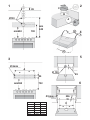
INSTALLATION
The hood is available in the ducting version (air evacuated outside the room) or the filtering version (air recirculated
inside the room).
1) The following operations are essential for assembly:
Install a proper wiring system.
If your apparatus is to be assembled as a Ducting appliance, you must first make the air venting hole and get a
proper pipe to connect the hole to the flange of the hood; use an outlet pipe with: - minimum indispensable length;
- minimum possible bends (maximum angle of bend:90°); - certified material (according to the State); - an as smooth
as possible inside. It is also advisable to avoid any drastic changes in pipe cross-section (recommended diameter:
125 mm). For air evacuation to the outside, follow all the instructions given on the “Warnings” sheet.
Make an air evacuation hole in the wall (diameter 133 mm) as shown in Fig. 1 which gives all the measurements required
for the various possible installations.
2) The hood is fitted with two air outlets, one at the top (Fig. 2B) and one at the rear (Fig. 2A), which can
be used according to requirements. In the ducting version, mount the flange (C) on the opening used and close
the other opening with the plug (E). In the filtering version, close both openings with the two plugs (E).
3) Wall mounting : Drill 4 holes in the wall using the measurements shown in Fig. 3 and insert the screw anchors;
take 2 of the supplied screws (Fig. 4G) and screw them into the uppermost anchors without tightening them. Attach
the hood to the 2 screws and, working from inside, fully tighten them. Complete mounting by inserting and tightening
the other 2 screws H (Fig. 4).
4) Mounting under a wall unit : If the ducting version of the hood is mounted with the air outlet in the upper opening
(Fig. 2B), before mounting, drill a 133 mm diameter hole in the wall unit (Fig. 5).
Drill 4 holes in the wall unit using the measurements shown in Fig. 6. Attach the hood with 4 screws working from inside
the wall unit (the 4 screws are not supplied).
5) For the ducting version: connect a flex tube to the hood flange using a metal retainer clamp. The tube and clamp
are not included in the supply.
6) Make the electrical connection.
7) CHECK THAT THE DUCTING-FILTERING LEVER IS IN THE RIGHT POSITION: The lever is found on the motor
unit and must be positioned on the symbol (P) in the case of installation in ducting version, on the symbol (Q) in
the case of installation in filtering version (Fig. 7).
8) CHARCOAL FILTER/S (A) - Fig. 8: one or more charcoal filters are required in the filtering version. If they are not
yet installed in the hood, fit them inside the grease filter/grille (M). Charcoal filters are not required In the ducting version.
If they are already installed in the hood remove them together with the relative filter retainers.

OPERATION
Controls (Fig. 9):
A = light switch.
B = first speed motor ON/OFF switch.
C = second speed switch.
D = third speed switch.
E = warning light: indicates motor operation.
Grease filter/s (Fig. 10N): this is a metal filter and is positioned inside the metal grid; the filter must be periodically
cleaned, depending on extent of operation (at least every two months). Wash the filter with neutral detergent. Remove
the 2 filter retainers (M) and the metal panel filter.
Charcoal filter/s: Replace the charcoal filters once every 6 months or at a different frequency depending on how often
they are used. To replace the charcoal filters (A), remove the filter retainers M (Fig. 8).
Lighting: To replace the lamps unscrewing the setscrew and remove the light fitting “A” (Fig. 11). Replace with a neon
lamp of the same type.
FRANCAIS
ATTENTION
La distance minimum entre la surface de support des casseroles sur le plan de cuisson et la partie inférieure de la hotte
doit être de 35 cm. Si les consignes, pour l’installation du plan de cuisson, indiquent une plus grande distance, il faut
en tenir compte.
L'air aspiré ne doit pas être canalisé dans un conduit qui est utilisé pour évacuer les fumées produites par des appareils
alimentés par des sources d'énergies autres que l'énergie électrique (installations de chauffage central, radiateurs,
chauffe-eau, etc.).
Pour évacuer l'air qui doit être éliminé respectez les prescriptions des autorités compétentes. De plus l'air qui doit être
évacué ne doit pas être déchargé dans une cavité du mur, à moins que cette cavité soit prévue pour ce but.
Prévoyez une aération de la pièce adéquate quand une hotte et des appareils alimentés par une énergie autre que l'énergie
électrique (poêle à gaz, à huile, à charbon etc.) sont utilisés en même temps. En effet, en évacuant l'air, la hotte pourrait
créer une dépression dans la pièce. La pression négative de la pièce ne doit pas dépasser 0,04mbar, évitant ainsi que
la source de chaleur provoque un appel des gaz qui doivent être évacués. Il est donc nécessaire d'équiper la pièce de
prises d'air alimentant un flux d'air frais constant.
Contrôler la plaque des caractéristiques techniques se trouvant à l’intérieur de l’appareil; si le symbole ( ) figure
sur la plaque suivre les instructions suivantes: cet appareil est construit pour appartenir à la classe d’isolation
II ; il ne doit donc pas être relié à la terre.
Contrôler la plaque des caractéristiques techniques se trouvant à l’intérieur de l’appareil; si le symbole ( ) NE
figure pas sur la plaque suivre les instructions suivantes: ATTENTION: cet appareil doit être relié à la terre. Lors
du raccordement électrique s’assurer que la prise de courant est équipée d’une connexion de mise à la terre.
Lors du raccordement électrique assurez-vous que les valeurs de tension correspondent à celles qui sont indiquées sur
la plaque des caractéristiques de l’appareil, qui se trouve à l'intérieur de celui-ci. Si votre appareil, n'a pas de câble flexible
qui ne peut pas être séparé ni de prise, ou bien d'autre dispositif qui garantisse le débranchement de tous les pôles du
réseau, avec une distance d'ouverture entre les contacts d'au moins 3 mm, ces dispositifs de séparation du réseau doivent
alors être prévus dans l'installation fixe. Si votre appareil est muni d’un câble d’alimentation, positionner l’appareil de
manière à ce que la fiche soit accessible.
Avant de procéder à une opération d’entretien ou de nettoyage quelconque, débranchez l’appareil.
UTILISATION
Evitez d'utiliser des matériaux qui provoquent des flammes à proximité de l'appareil.
Dans le cas de fritures, faites tout particulièrement attention au danger d’incendie que représentent les huiles et les corps
gras. A cause de son inflammabilité l’huile usagée est particulièrement dangereuse. N'utilisez pas de grils électriques
découverts.
Pour éviter des risques d'incendie possibles suivez les instructions données concernant le nettoyage des filtres à graisse
et sur la façon d'enlever des dépôts éventuels de graisse sur l'appareil.
ENTRETIEN
Un entretien soigné est une garantie de bon fonctionnement et de bon rendement de votre appareil dans le temps.
L’élimination, d’éventuels dépôts de graisse sur l’appareil, doit être effectuée en fonction de l’utilisation de ce dernier
(au moins tous les 2 mois). Il faut éviter d’utiliser des produits contenant des abrasifs ou des corrosifs. Pour le nettoyage
extérieur des appareils peints, utiliser un chiffon mouillé avec de l’eau tiède et un détersif neutre. Pour le nettoyage extérieur
des appareils en acier, en cuivre et en laiton il est conseillé d’utiliser des produits spécifiques et de suivre les instructions
fournies sur le produit. Pour le nettoyage de l’intérieur de l’appareil, utiliser un chiffon (ou un pinceau) imbibé d’alcool
dénaturé.

85
Ø133
720
min
940
min650
C
E
2
B
A
1
Ø 8mm
A
44
732
min650
=
=
MODELS A X
50cm 44cm 41cm
55cm 49cm 46cm
60cm 54cm 51cm
70cm 64cm 61cm
80cm 74cm 71cm
90cm 84cm 81cm
3
4
G
H
5
Ø 133
85
6
Ø 6mm
X
35
256
=
=

7
P
Q
9
A
B
C
D
E
8
A
M
10
N
M
11
-
 1
1
-
 2
2
-
 3
3
-
 4
4
-
 5
5
-
 6
6


Küppersbusch D633.1 Instructions For Use And Installation Instructions
- Taper
- Instructions For Use And Installation Instructions
dans d''autres langues
- English: Küppersbusch D633.1
- Deutsch: Küppersbusch D633.1