Astria Fireplaces MLDVT Guide d'installation
- Catégorie
- Cheminées
- Taper
- Guide d'installation

INSTALLATION INSTRUCTIONS
Please read and understand these instructions
before starting installation.
INSTALLER: Leave this manual with the appliance.
CONSUMER: Retain this manual for future reference.
INSTALLATEUR : Laissez cette notice avec l’appareil.
CONSOMMATEUR : Conservez cette notice pour
consultation ultérieure.
AVERTISSEMENT : Assurez-vous de bien suivre les
instructions données dans cette notice pour réduire au
minimum le risque d’incindie ou d’explosion ou pour
éviter tout dommage matériel, toute blessure ou la mort.
WARNING: If the information in these instructions
is not followed exactly, a fire or explosion may
result, causing property damage, personal injury,
or death.
WARNING /AVERTISSEMENT/AVISO
• HOT GLASS WILL CAUSE
BURNS.
• DO NOT TOUCH GLASS
UNTIL COOLED.
• NEVER ALLOW CHILDREN
TO TOUCH GLASS.
• UNE SURFACE VITRÉE CHAUDE
PEUT CAUSER DES BRÛLURES.
• LAISSER REFROIDIR LA SURFACE
VITRÉE AVANT D'Y TOUCHER.
• NE PERMETTEZ JAMAIS À UN ENFANT
DE TOUCHER LA SURFACE VITRÉE.
• EL VIDRIO CALIENTE
CAUSARÁ QUEMADURAS.
• USTED DEBE NUNCA
TOCAR EL VIDRIO CALIENTE.
• LOS NIÑOS DEBEN NUNCA
TOCAR EL VIDRIO.
- Do not store or use gasoline or other flammable
vapors and liquids in the vicinity of this or any other
appliance.
- WHAT TO DO IF YOU SMELL GAS:
• Do not try to light any appliance.
• Do not touch any electrical switch; do not use any
phone in your building.
• Immediately call your gas supplier from a
neighbor’s phone. Follow the gas supplier’s
instructions.
• If you cannot reach your gas supplier, call the fire
department.
- Installation and service must be performed by a
qualified installer, service agency or the gas supplier.
- Ne pas entreposer ni utilizer d’essence ni d’autres vapeurs
ou liquides inflammables dans le voisinage de cet appareil
ou de tout autre appareil.
- QUE FAIRE SI VOUS SENTEZ UNE ODEUR DE GAZ :
• Ne pas tenter d’allumer d’appareil.
• Ne touchez à aucan interrupteur. Ne pas vous servir des
téléphones se trouvant dans le bâtiment où vous trouvez.
• Appelez immédiatement votre fournisseur de gaz depuis
un voisin. Suivez les instructions du fournisseur.
• Si vous ne pouvez rejoindre le fournisseur de gaz,
appelez le service des incindies.
- L’installation et l’entretien doivent être assurés par un
installateur ou un service d’entretien qualifié ou par le
fournisseur de gaz.
P/N 506015-10 Rev. B 04/2013
This manual is one of a set of two supporting this product.
Refer to P/N 506017-09 for Care and Operation Instructions.
Ce manuel est disponible en francais, simplement
en faire la demande. Numéro de la pièce 506223-56.
This appliance may be installed in an aftermarket permanently located, manufactured home (USA only) or mobile
home, where not prohibited by local codes. This appliance is only for use with the type of gas indicated on the
rating plate. This appliance is not convertible for use with other gases, unless a certified kit is used.
Report No. 100326540PRT-001
ELECTRONIC:MILLIVOLT:
MLDVT Direct-Vent
Gas Fireplaces
MLDVT30NE-2
MLDVT35NE-2
MLDVT-35NE-FB
MLDVT40NE-2
MLDVT-40NE-FB
MLDVT45NE-2
MLDVT-30PM
MLDVT-35PM
MLDVT-35PM-FB
MLDVT-40PM
MLDVT-45PM
MLDVT-30NM
MLDVT-35NM
MLDVT-35NM-FB
MLDVT-40NM
MLDVT-40NM-FB
MLDVT-45NM
MODELS
™

DIAGRAMS & ILLUSTRATIONS ARE NOT TO SCALE.
2
LENNOX HEARTH PRODUCTS • MERIT® SERIES DIRECT-VENT GAS FIREPLACES • MLDVT-30/35/40/45 • INSTALLATION INSTRUCTIONS
TABLE OF CONTENTS
Packaging ............................ 2
Introduction .......................... 2
General Information .................... 2
Requirements for the Commonwealth
of Massachusetts ...................... 4
Cold Climate Insulation.................. 4
Manufactured Home Requirements ........ 5
Location ............................. 5
Vent Termination Clearances ............. 6
Minimum Clearance to Combustibles ....... 8
Pre-Installation Steps ................... 8
Typical Installation Sequence ............. 9
Detailed Installation Steps................ 9
Optional Blower Kit Wiring ............... 9
Framing.............................. 9
Fireplace and Framing Specifications ...... 10
Routing Gas Line ..................... 11
Installing the Venting System . . . . . . . . . . . . 12
Vertical Termination Systems ............ 12
Vent Section Length Chart .............. 13
Vertical Vent Tables and Figures .......... 16
Horizontal Vent Tables and Figures ........ 20
Venting Using Flexible Vent Pipe.......... 22
Field Wiring.......................... 23
Optional Blower Kit Wiring .............. 24
Connecting Gas Line................... 24
Verifying Appliance Operation............ 25
Installing Logs ....................... 26
Removing/Installing Glass Door .......... 29
Adjusting Burner...................... 29
Installing Hood ....................... 31
Finishing Requirements ................ 31
Attaching Safety-in-Operation Warnings.... 32
Installation Accessories ................ 33
Gas Conversion Kits ................... 35
Please read and understand these
instructions before beginning
your installation.
PACKAGING
The assembled vented gas fireplace heater
is packaged with:
• (1 set) Logs
(Packaged in a carton inside the firebox)
• (1 bag) Volcanic Stone
(In bottom compartment)
• (1 bag) Glowing Embers
(In bottom compartment)
• Literature Kit
(Envelope in bottom compartment
containing Care and Operation
Instructions, Installation Instructions,
Safety-In-Operation Warning Labels,
Warranty)
• (1) U-Shaped Vent Restrictor
(Attached to Literature Kit envelope)
• (1) Hood
(Inside firebox)
INTRODUCTION
Millivolt appliances have a millivolt gas
control valve with piezo ignition system. If
any optional accessories that will require
electrical power are to be installed, the
electrical power must be provided at the
time of appliance installation.
Electronic appliances are designed to
operate on natural or propane gas. An
electronic intermittent pilot ignition system
provides safe, efficient operation. External
electrical power is required to operate
these units. In the event of a power outage,
four (4) “AA” batteries (in battery holder)
provide backup power for appliance
operation (excluding [optional] blower).
These vented gas fireplace heaters
are sealed combustion, air-
circulating gas fireplaces designed for
residential applications.
Approved Vent Components
These fireplaces are designed, tested and
listed for operation and installation with the
following vent components only:
• Secure Vent® Direct-Vent System
Components manufactured by Security
Chimneys International,
• Secure Flex® Flexible Vent Components
manufactured by Security Chimneys
International, and
• Z-FLEX® Model GA Venting Systems
listed to UL1777 and ULCS635
manufactured by Flexmaster
Canada Limited.
Use only the correct size venting (4 1/2 in.
inner and 7 1/2 in. outer).
These approved vent system components
are labeled for identification. DO NOT use
any other manufacturer’s vent components
with these appliances.
GENERAL INFORMATION
WARNING
Young children should be
carefully supervised when
they are in the same room
as the appliance. Toddlers,
young children and others may
be susceptible to accidental
contact burns. A physical
barrier is recommended if
there are at-risk individuals in
the house. To restrict access
to a fireplace or stove, install
an adjustable safety gate to
keep toddlers, young children
and other at risk individuals
out of the room and away from
hot surfaces.
AVERTISSEMENT
Les jeunes enfants devraient
être surveillés étroitement
lorsqu’ils se trouvent dans la
même pièce que l’appareil.
Les tout petits, les jeunes
enfants ou les adultes
peuvent subir des brûlures
s’ils viennent en contact
avec la surface chaude. Il
est recommandé d’installer
une barrière physique si des
personnes à risques habitent
la maison. Pour empêcher
l’accès à un foyer ou à un
poêle, installez une barrière
de sécurité; cette mesure
empêchera les tout petits,
les jeunes enfants et toute
autre personne à risque
d’avoir accès à la pièce et aux
surfaces chaudes.
NOTE: Children and adults should be alerted
to the hazards of high surface temperature
and should stay away to avoid burns or
clothing ignition.
Remarqué : Les enfants et les adultes
devraient être infor-més des dangers
que posent les températures de surface
élevées et se tenir à distance afin d’éviter
des brûlures ou que leurs vêtements ne
s’enflamment.
DO NOT ATTEMPT TO ALTER OR
MODIFY THE CONSTRUCTION OF THE
APPLIANCE OR ITS COMPONENTS.
ANY MODIFICATION OR ALTERATION
MAY VOID THE WARRANTY,
CERTIFICATION, AND LISTINGS OF
THIS UNIT.

DIAGRAMS & ILLUSTRATIONS ARE NOT TO SCALE.
3
LENNOX HEARTH PRODUCTS • MERIT® SERIES DIRECT-VENT GAS FIREPLACES • MLDVT-30/35/40/45 • INSTALLATION INSTRUCTIONS
Codes and Standards
These appliances comply with National
Safety Standards and are tested and
listed by ETL/Intertek. (Report No.
100326540PRT-001) to ANSI Z21.88
(in Canada, CSA-2.33), and CAN/
CGA-2.17-M91 in both USA and Canada, as
vented gas fireplace heaters.
These appliances are listed by ETL/
Intertek for installation in bedrooms and
manufactured homes.
The installation must conform to local
codes or, in the absence of local codes, with
the National Fuel Gas Code, ANSI Z223.1/
NFPA 54—latest edition (In Canada, the
current CAN/CSA-B149.1 installation code).
The appliance, when installed, must
be electrically grounded and wired in
accordance with local codes or, in the
absence of local codes, with the National
Electrical Code, ANSI/NFPA 70—latest
edition, or the Canadian Electrical Code,
CSA C22.1—latest edition.
Provide adequate clearances around
air openings and adequate accessibility
clearance for service and proper operation.
Never obstruct the front or back openings
of the appliance.
These appliances are designed to operate
on natural or propane gas only. The use
of other fuels or combination of fuels will
degrade the performance of this system and
may be dangerous.
It is advisable to have an alternate primary
heat source when installed in a dwelling.
These appliances must not be connected to
a chimney or flue serving a separate solid
fuel burning appliance.
Electronic models come standard with
a remotely-modulated gas valve. Flame
appearance and heat output cannot be
controlled at the gas valve. The BTU Input
for these appliances is shown in Table 1.
Table 1: Input Rate, Gas Valves
Models Input Rate (BTU/HR)
Natural Gas Propane Gas
MLDVT-30 13,500 high
10,500 low 12,500 high
9,000 low
MLDVT-35 16,000 high
12,500 low 15,000 high
11,500 low
MLDVT-40 20,000 high
15,500 low 20,000 high
15,800 low
MLDVT-45 23,000 high
17,500 low 22,000 high
17,000 low
WARNING
Failure to position the parts in
accordance with these diagrams
or failure to use only parts
specifically approved with this
appliance may result in property
damage or personal injury.
AVERTISSEMENT
Risque de dommages ou de
blessures si les pièces ne sont
pas installées conformément à
ces schémas et ou si des pièces
autres que celles spécifiquement
approuvées avec cet appareil
sont utilisées.
NOTE: Installation and repair should be
done by a qualified service person. The
appliance should be inspected before use
and at least annually by a professional
service person. More frequent cleaning
may be required due to excessive lint from
carpeting, bedding material, etcetera. It
is imperative that control compartments,
burners and circulating air passageways of
the appliance be kept clean.
Remarqué : L’installation et la
réparation devrait être confiées à un
technicien qualifié. L’appareil devrait
faire l’objet d’une inspection par un
technicien professionnel avant d’être
utilisé et au moins une fois l’an par la
suite. Des nettoyages plus fréquents
peuvent être nécessaires si les tapis,
la literie, et cetera produisent une
quantité importante de pous-sière. Il
est essentiel que les compartiments
abritant les commandes, les brûleurs
et les conduits de circulation d’air de
l’appareil soient tenus propres.
NOTE: Do not use these appliances if any
part has been under water. Immediately call
a qualified, professional service technician
to inspect the appliance and to replace any
parts of the control system and any gas
control which have been under water.
Remarqué : Ne pas utiliser cet appareil
s’il a été plongé, même partiellement,
dans l’eau. Appeler un technicien
qualifié pour inspecter l’appareil et
remplacer toute partie du système de
commande et toute commande qui a été
plongée dans l’eau.
NOTE: Only trim kit(s) supplied by
the manufacturer shall be used in the
installation of this appliance.
Remarqué : Seules les trousses de
garniture fournies par le fabricant
doivent être utilisées pour l’installation
de cet appareil.
WARNING
Improper installation,
adjustment, alteration, service
or maintenance can cause injury
or property damage. Refer to
this manual. For assistance or
additional information consult
a qualified installer, service
agency or the gas supplier.
WARNING
Failure to comply with these
installation instructions will
result in an improperly installed
and operating appliance, voiding
its warranty. Any change to this
appliance and/or its operating
controls is dangerous.
WARNING
Clothing or other flammable
material should not be placed on
or near the appliance.
AVERTISSEMENT
On ne devrait pas placer de
vêtements ni d’autres matières
inflammables sur l’appareil ni à
proximité.
WARNING
Any safety screen or guard
removed for servicing the
appliance must be replaced prior
to operating the appliance.
AVERTISSEMENT
Tout écran ou protecteur retiré
pour permettre l’entretien de
l’appareil doit être remis en
place avant de mettre l’appareil
en marche.
WARNING
Improper installation or use of
this appliance can cause serious
injury or death from fire, burns,
explosion or carbon monoxide
poisoning.

LENNOX HEARTH PRODUCTS • MERIT® SERIES DIRECT-VENT GAS FIREPLACES • MLDVT-30/35/40/45 • INSTALLATION INSTRUCTIONS
DIAGRAMS & ILLUSTRATIONS ARE NOT TO SCALE.
4
REQUIREMENTS FOR THE
COMMONWEALTH OF
MASSACHUSETTS
These fireplaces are approved for
installation in the U.S. state of
Massachusetts if the following additional
requirements are met:
• Install this appliance in accordance with
Massachusetts Rules and Regulations
248 C.M.R..
• Installation and repair must be done by
a plumber or gas fitter licensed in the
Commonwealth of Massachusetts.
• The flexible gas line connector used
shall not exceed 36 in. (92 cm)
in length.
• The individual manual shut-off must be
a T-handle type valve.
Massachusetts Horizontal Vent
Requirements
In the Commonwealth of Massachusetts,
horizontal terminations installed less than
seven (7) feet above the finished grade
must comply with the following additional
requirements:
• A hard wired carbon monoxide detector
with an alarm and battery back-up must
be installed on the floor level where the
gas fireplace is installed. The carbon
monoxide detector must comply with
NFPA 720, be ANSI/UL 2034 listed and
be ISA certified.
• A metal or plastic identification plate
must be permanently mounted to the
exterior of the building at a minimum
height of eight (8) feet above grade and
be directly in line with the horizontal
termination. The sign must read, in
print size no less than one-half (1/2)
inch in size, GAS VENT DIRECTLY
BELOW. KEEP CLEAR OF ALL
OBSTRUCTIONS.
COLD CLIMATE INSULATION
For cold climate installations, seal all cracks
around your appliance with noncombustible
material and wherever cold air could enter
the room. It is especially important to
insulate outside chase cavity between studs
and under floor on which appliance rests, if
floor is above ground level. Gas line holes
and other openings should be caulked or
stuffed with unfaced fiberglass insulation.
If the fireplace is being installed on a
cement slab in cold climates, a sheet of
plywood or other raised platform can be
placed underneath to prevent conduction
of cold transferring to the fireplace and
into the room. It also helps to sheetrock
inside surfaces and tape for maximum air
tightness and caulk firestops.
The appliance and its appliance main gas
valve must be disconnected from the gas
supply piping system during any pressure
testing of that system at test pressures in
excess of 1/2 psi (3.5 kPa).
The appliance must be isolated from
the gas supply piping system by closing
its equipment shutoff valve during any
pressure testing of the gas supply piping
system at test pressures equal to or less
than 1/2 psi (3.5 kPa).
Orifice Sizes—Sea Level to
High Altitude
These appliances are tested and approved
for installation at elevations of 0–4500 ft
(0–1372 m) above sea level using the
standard burner orifice sizes (marked with
an “*” in Table 4).
For elevations above 4500 ft, contact your
gas supplier or qualified service technician.
Deration
At higher elevations, the amount of BTU fuel
value delivered must be reduced by either:
• Using gas that has been derated by the
gas company.
• Changing the burner orifice to a
smaller size as regulated by the local
authorities having jurisdiction and by
the (USA) National Fuel Gas Code NFPA
54/ANSI Z223.1—latest edition or, in
Canada, the CAN/CSA-B149.1 codes—
latest edition.
NOTE: Flame breadth, height and width will
diminish 4% for every 1,000 feet of altitude.
Table 4: Burner Orifice Sizes,
Elevation 0–4500 ft ( 0–1372 m)
Model Natural Gas
drill size
(inches)
Propane
drill size
(inches)
MLDVT-30 #50 (0.070 in.)*
H4873•
#59 (0.041 in.)*
H7838•
MLDVT-35 (0.0748 in.)*
H1355•
(0.045 in.)*
75L10•
MLDVT-40 #44 (0.086 in.)*
60J80•
#55 (0.052 in.)*
19L52•
MLDVT-45 (0.090 in.)*
37L70•
#54 (0.055 in.)*
99K79•
* Standard size installed at factory
• Catalog number
In Canada—CAN/CGA-2.17-M91
(high altitude):
THE CONVERSION SHALL BE CARRIED
OUT BY A MANUFACTURER’S
AUTHORIZED REPRESENTATIVE, IN
ACCORDANCE WITH THE REQUIREMENTS
OF THE MANUFACTURER, PROVINCIAL
OR TERRITORIAL AUTHORITIES HAVING
JURISDICTION AND IN ACCORDANCE
WITH THE REQUIREMENTS OF THE
CAN/CGA-B149.1 OR CAN/CGA-B149.2
INSTALLATION CODES.
Gas Pressure
Table 2 and Table 3 show the appliance
inlet and manifold gas pressure
requirements.
Table 2: Inlet Gas Supply Pressure
Fuel Minimum Maximum
Natural Gas 4.5 in. WC
(1.12 kPa) 10.5 in. WC
(2.61 kPa)
Propane 11.0 in. WC
(2.74 kPa) 13.0 in. WC
(3.23 kPa)
Table 3: Manifold Gas Supply Pressure
Fuel Low High
Natural Gas 2.2 in. WC
(0.55 kPa) 3.5 in. WC
(0.87 kPa)
Propane 6.3 in. WC
(1.57 kPa) 10.0 in. WC
(2.49 kPa)
Test gauge connections are provided on
the front of the electronic gas control valve
(identified IN for the inlet and OUT for the
manifold side). The control valves have a
3/8 in. (10 mm) NPT thread inlet and outlet
side of the valve (Figure 1 and Figure 2 ).
Figure 1: SIT Millivolt Gas Valve
H
I
LO
W
HTPTHTPT
P
I
L
O
T
P
I
L
O
T
O
N
it
O
F
F
IN OUT
HI/LO Variable
Flame Height
Adjustment
Manifold Pressure Tap
Inlet Pressure Tap
Pilot Adjustment
Screw
Main Gas Control Knob
OFF/PILOT/ON
Figure 2: SIT Electronic Gas Valve
Orange Wire
(from DFC
Wire
Harness)
Main
Gas Inlet
3/8 in. NPT
Green Wire
(from DFC Wire
Harness)
Inlet (IN) Test Port
Manifold (OUT)
Test Port
Hi/Lo
Flame
Control
Knob
Yellow Ground Wire
(from DFC
Wire Harness)
Propane tanks are at pressures that will
cause damage to valve components. Verify
that the tanks have step down regulators to
reduce the pressure to safe levels.

LENNOX HEARTH PRODUCTS • MERIT® SERIES DIRECT-VENT GAS FIREPLACES • MLDVT-30/35/40/45 • INSTALLATION INSTRUCTIONS
DIAGRAMS & ILLUSTRATIONS ARE NOT TO SCALE.
5
The minimum height from the base of the
appliance to the underside of combustible
materials used to construct a utility shelf in
this fashion is shown in Table 8.
The appliance must be mounted on a
fully supported base extending the full
width and depth of the unit. The appliance
may be located on or near conventional
construction materials. However, if
installed on combustible materials, such as
carpeting, vinyl tile or other combustible
material other than wood flooring, the
appliance shall be installed on a metal or
wood panel extending the full width and
depth of the appliance.
LOCATION
In selecting the location, the aesthetic and
functional use of the appliance are primary
concerns. However, vent system routing to
the exterior and access to the fuel supply
are also important.
Due to high temperatures, the appliance
should be located out of traffic and away
from furniture and draperies (Figure 3).
En raison des températures élevées,
l’appareil devrait être installé dans
un endroit où il y a peu de circulation
et loin du mobilier et des tentures
(Figure 3).
Figure 3: Typical Locations
NOITACILPPA
TNEVPOT
APPLICATION
TOP VENT
TNEVPOT
NOITACILPPA
RECESSED
INSTALLATION
TOP VENT
APPLICATION
NOITACILPPA
TNEVPOT
NOITACILPPA
TNEVPOT
HORIZONTAL VENT
(Top Vent Application)
VERTICAL VENT
(Top Vent Application)
NOTE: When the unit is installed with
one side flush with a wall, the wall
on the other side of the unit must
not extend beyond the front edge of
the unit.
The location should also be free of
electrical, plumbing or other heating/air
conditioning ducting.
These direct-vent appliances are uniquely
suited for installations requiring a utility
shelf positioned directly above the fireplace.
Utility shelves like these are commonly
used for locating television sets and
decorative plants.
Be aware that this is a heat producing
appliance. Objects placed above the unit are
exposed to elevated temperatures.
Do not insulate the space between the
appliance and the area above it (Table 8).
MANUFACTURED HOME
REQUIREMENTS
This appliance may be installed in
an aftermarket permanently located,
manufactured home and must be installed
in accordance with the manufacturer’s
instructions.
Cet appareil peut être installé cómme
du matéri-el d’origine dans une maison
préfabriquée (É.U. seulement) ou
mobile et doit être installé selon les
instructions du fabricant.
This appliance is only for use with the type
of gas indicated on the rating plate. This
appliance is not convertible for use with
other gases, unless a certified kit is used.
Cet appareil doit être utilisé uniquement
avec le type de gaz indiqué sur la plaque
signalétique. Cet appareil ne peut être
converti à d’autres gaz, sauf si une
trousse de conversion est utilisée.
CAUTION
Ensure that the cross members
are not cut or weakened during
installation. The structural
integrity of the manufactured
home floor, wall, and ceiling /
roof must be maintained.
CAUTION
This appliance must be
grounded to the chassis of
the manufactured home in
accordance with local codes or
in the absence of local codes,
with the National Electrical Code
ANSI / NFPA 70—latest edition or
the Canadian Electrical Code CSA
C22.1—latest edition.

LENNOX HEARTH PRODUCTS • MERIT® SERIES DIRECT-VENT GAS FIREPLACES • MLDVT-30/35/40/45 • INSTALLATION INSTRUCTIONS
DIAGRAMS & ILLUSTRATIONS ARE NOT TO SCALE.
6
Horizontal Vent
Termination Clearances
The horizontal vent termination must have
a minimum of 6 in. (152 mm) clearance
to any overhead combustible projection of
2 1/2 in. (64 mm) or less. For projections
exceeding 2 1/2 in. (64 mm), see Figure 7.
For additional vent location restrictions,
refer to Table 6.
Figure 6: Horizontal Vent Termination
Clearances, Side Elevation
6"
(152 mm)
12"
(305 mm)
Combustible Projection greater
Combustible Projection
2-1/2 inches or less in length
18"
(457 mm)
Ventilated
Soffit Unventilated
Soffit
than 2-1/2 inches in length
Termination Kit
Figure 7: Horizontal Vent Termination
Clearances
Termination Kit
All horizontal terminations
may be located as close as
6” (152mm) to any
(non-combustible and
combustible) exterior
sidewall. This distance
may be decreased to 2”
(51mm) for non--
combustible exterior
sidewalls only, if the
SV4.5HT-2 termination
is used.
Figure 5: Vertical Vent Termination
Clearances
12
X
Roof Pitch is X/12
2 FT
MIN.
2 FT MIN.
Lowest
Discharge
Opening
H*
*H = MINIMUM HEIGHT FROM ROOF TO
LOWEST DISCHARGE OPENING OF VENT
TERMINATION HEIGHTS FOR VENTS ABOVE
FLAT OR SLOPED ROOFS
Horizontal Overhang
Vertical
Wall
Vent
Termination
Storm Collar
Concentric
Vent Pipe
Flashing
1 inch (25.4 mm) Minimum
Clearance to Combustibles
Table 5: Termination Heights for Vents
above Flat or Sloped Roofs
Roof Pitch Feet * Meters *
Flat to 6 1/2 10.3
6 1/2 to 7 1/2 1 1/4 0.38
7 1/2 to 8 1/2 1 1/2 0.46
8 1/2 to 9 1/2 20.61
9 1/2 to 10 1/2 2 1/2 0.76
10 1/2 to 11 1/2 3 1/4 0.99
11 1/2 to 12 1/2 41.22
12 1/2 to 14 1/2 51.52
14 1/2 to 16 1/2 61.83
16 1/2 to 18 1/2 72.13
18 1/2 to 201/2 7 1/2 2.29
20 1/2 to 21 1/2 82.44
VENT TERMINATION CLEARANCES
These instructions should be used
as a guideline and do not supersede
local codes in any way. Install venting
according to local codes, these
instructions, the current National
Fuel Gas Code (ANSI-Z223.1) in the
USA or the current standards of CAN/
CSA-B149.1 in Canada.
Vertical Vent Termination Clearances
Terminate multiple vent terminations
according to the installation codes listed
above, Figure 4, Figure 5, and Table 5.
Figure 4: Multiple Terminations
12 in.
(305 mm)
Minimum

LENNOX HEARTH PRODUCTS • MERIT® SERIES DIRECT-VENT GAS FIREPLACES • MLDVT-30/35/40/45 • INSTALLATION INSTRUCTIONS
7
Table 6: Exterior Horizontal Vent Termination Clearances
V
VV
V
V
F
C
Fixed
Closed
Window
Operable
Window
B
B
A
B
H
M
I
= Area where Termination is not Permitted
= Air Supply Inlet
X= Vent Termination
V
D
V
3 ft
3 ft
11
1
= 9 in. in U.S.
= 12 in. in Canada
V
L
B
J
X
V
A
G
Inside
Corner Detail
B
C
C
C
*18 in.
Ventilated Soffit
Horizontal
Termination
Detail D
Exterior Wall
6 in.
Inside Corner
* See Item D in the Text Below.
V
P
V
O
NN
Q
NOTE: Local Codes Or Regulations
May Require Different Clearances.
NOTE: Location Of The Vent Termination
Must Not Interfere With Access To The
Electrical Service.
E
K
X
U.S. Installation ** Canadian Installation *
AClearance above grade, veranda, porch, desk, or balcony 12 in. (300 mm) ** 12 in. (300 mm) *
BClearance to window or door that may be opened 6 in. (150 mm)
for appliances < 10,000 Btuh (3 kW),
9 in. (230 mm)
for appliances > 10,000 Btuh (3 kW), and < 50,000 Btuh (15 kW),
12 in. (300 mm)
for appliances > 50,000 Btuh (15 kW) **
6 in. (150 mm)
for appliances < 10,000 Btuh (3 kW),
12 in. (300 mm)
for appliances > 10,000 Btuh (3 kW)
CClearance to permanently closed window 9 in. (229 mm)
recommended to prevent window condensation 12 in. (305 mm)
recommended to prevent
window condensation
DVertical clearance to ventilated soffit located above the
termination within a horizontal distance of 18 in. (458 mm) 18 in. (458 mm) 18 in. (458 mm)
EClearance to unventilated soffit 12 in. (305 mm) 12 in. (305 mm)
FClearance to outside corner 5 in. (127 mm)
minimum 5 in. (127 mm)
minimum
GClearance to inside corner 2 in. (50.8 mm)
minimum—SV4.5HT-2 •
6 in. (152 mm)
minimum—SV4.5HTSS
2 in. (50.8 mm)
minimum—SV4.5HT-2 •
6 in. (152 mm)
minimum—SV4.5HTSS
HClearance to each inside of center line extended above
meter / regulator assembly 36 in. (910 mm)
within a height of 15 ft above the meter / regulator assembly ** 36 in. (910 mm)
within a height of 15 ft above the meter /
regulator assembly *
IClearance to service regulator vent outlet 36 in. (910 mm)** 36 in. (910 mm)*
JClearance to nonmechanical air supply inlet to building or
the combustion air inlet to any other appliance 6 in. (150 mm)
for appliances < 10,000 Btuh (3 kW),
9 in. (230 mm)
for appliances > 10,000 Btuh (3 kW) and < 50,000 Btuh (15 kW),
12 in. (300 mm)
for appliances > 50,000 Btuh (15 kW)**
6 in. (150 mm)
for appliances < 10,000 Btuh (3 kW),
12 in. (300 mm)
for appliances > 10,000 Btuh (3 kW)
KClearance to a mechanical air supply inlet 36 in. (910 mm) above if within 10 ft (3 m) horizontally ** 72 in. (1830 mm) *
LClearance above paved sidewalk or paved diveway located
on public property 84 in. (2130 mm) ‡ 84 in. (2130 mm) ‡
MClearance under veranda, porch, deck or balcony 12 in. (300 mm) *‡ 12 in. (300 mm) *‡
NDepth of alcove (maximum) 72 in. (1830 mm) ** 72 in. (1830 mm) *
OClearance to termination (alcove) 6 in. (15.2 mm) ** 6 in. (15.2 mm)*
PWidth of alcove (minimum) 36 in. (910 mm) ** 36 in. (910 mm) *
QClearance to combustible above (alcove) 18 in. (457 mm) ** 18 in. (457 mm) *
*
**
‡
*‡
•
In accordance with the current CSA-B149.1 National Gas And Propane Installation Code
In accordance with the curent ANSI SZ223.1/NFPA 54 National Fuel Gas Codes
A vent shall not terminate directly above a sidewalk or paved driveway which is located between two single family dwellings and serves both dwellings
Only permitted if veranda, porch, deck, or balcony is fully-open on a minimum two sides beneath the floor
2 in. clearance to non-combustibles for SV4.5HT-2 only

LENNOX HEARTH PRODUCTS • MERIT® SERIES DIRECT-VENT GAS FIREPLACES • MLDVT-30/35/40/45 • INSTALLATION INSTRUCTIONS
DIAGRAMS & ILLUSTRATIONS ARE NOT TO SCALE.
8
Figure 8: Minimum Mantel Clearances
8 (203)
2
(51)
4
(102)
6
(152)
8
(203)
10
(254)
12
(305)
10 (254)
14 (356)
18 (457)
16 (406)
12 (305) Top of
Appliance
inches (millimeters)
Mantel
Depth
Hood
Header
Figure 9: Minimum Distance to
Side Wall
3 1/2 in.
(89 mm)
6 in.
(152 mm)
Top View of
Fireplace
45o
Combustible
mantel legs may
project beyond either side
of the fireplace opening
as long as they are kept
within the shaded area
illustrated here.
Combustible Materials
Allowed In Shaded Area
“Safe Zone”
Combustible Walls
shown in dark gray
At 6 in. minimum
side wall clearance,
a combustible wall
can project to any
length.
Table 8: Shelf Height Minimum Clearances
Shelf Height
(see table)
Do not insulate the
space between the
appliance and the
area above it.
Models Top Vent—with One 90° Elbow
Secure Vent Secure Flex
MLDVT-30/35 46 1/2 in. (1181 mm) 48 1/4 in. (1226 mm)
MLDVT-40/45 51 1/2 in. (1308 mm) 53 1/4 in. (1349 mm)
Wall Finishes, Surrounds,
and Mantels
NOTE: Combustible wall finish materials
and/or surround materials must not be
allowed to encroach the area defined by the
appliance front face (black sheet metal).
Never allow combustible materials to be
positioned in front of or overlapping the
appliance face (Figure 39 on Page 31).
Non-combustible materials, such as
surrounds and other appliance trim,
may be installed on the appliance face,
but they must not cover any portion of
the removable glass panel or control
compartment.
Vertical installation clearances to
combustible mantels vary according to the
depth of the mantel (Figure 8). Mantels
constructed of non-combustible materials
may be installed at any height above the
appliance opening. However, do not allow
anything to hang below the fireplace hood.
Minimum clearance requirements include
any projections such as shelves, window
sills, mantels, etc. above the appliance.
NOTE: We recommend the use of high
temperature paint (rated 175 °F, or higher)
on the underside of the mantel.
MINIMUM CLEARANCE TO
COMBUSTIBLES
The appliance is approved with zero
clearance to combustible materials on
all sides (Table 7), with the following
exception: When the unit is installed with
one side flush with a wall, the wall on the
other side of the unit must not extend
beyond the front edge of the unit. In
addition, when the unit is recessed, the side
walls surrounding the unit must not extend
beyond the front edge of the unit (Figure 3).
Hearth Extension—A hearth extension is
not required with this appliance. If a hearth
extension is used, do not block the lower
control compartment door. Any hearth
extension used is for appearance only
and does not have to conform to standard
hearth extension installation requirements.
Shelf Height—To provide for the lowest
possible shelf surface, use the alternate
rear vent outlet, the venting attached to
the top vent should be routed in a way to
minimize obstructions to the space above
the appliance. Do not insulate the space
between the appliance and the area above
it (Table 8). The minimum height from the
base of the appliance to the underside of
combustible materials used to construct
a utility shelf in this fashion is shown in
Table 8.
The appliance should be mounted on a
fully supported base extending the full
width and depth of the unit. The appliance
may be located on or near conventional
construction materials. However, if
installed on combustible materials, such as
carpeting, vinyl tile, etc., a metal or wood
barrier covering the entire bottom surface
must be used.
Table 7: Minimum Clearances *
Back 1/2 in. (13 mm)
0 in. (0 mm) from Spacers or Dimples
Sides 1/2 in. (13 mm)
0 in. (0 mm) from Spacers or Dimples **
Top of
Fireplace
3 in. (76 mm)
0 in. (0 mm) with standoff(s) in vertical
position (Figure 10)
Floor 0 in. (0 mm)
From
Bottom
of Unit To
Ceiling
minimum of 64 in. (1626 mm)
Vent 3 in. (76 mm)—Top * ***
1 in. (25.4 mm)—Sides and Bottom
Front
Service 36 in. (914 mm)
* Note: 3 in. (75 mm) above any horizontal/
inclined vent component.
** Note: See Frame the Fireplace on Page 9
for clearance requirements to the nailing flange
located at each side of the unit and any screw heads
adjacent to it.
*** Note: Top vent clearance can be reduced to 2 in.
on horizontal runs when first elbow is located at
least 6 ft above the fireplace.

LENNOX HEARTH PRODUCTS • MERIT® SERIES DIRECT-VENT GAS FIREPLACES • MLDVT-30/35/40/45 • INSTALLATION INSTRUCTIONS
DIAGRAMS & ILLUSTRATIONS ARE NOT TO SCALE.
9
DETAILED INSTALLATION STEPS
Follow these steps to complete fireplace
installation:
Wire the [Optional] Blower Kit Before
Installation in the Framing
Remove the left side blower cover panel
screw, and blower cover panel (Table 11).
Retain the panel and screw for later
reinstallation.
Slide the blower through the opening
and position it with the bracket oriented
to the front of the firebox and the blower
discharge to the rear of the firebox. Bend
the two tabs in the firebox floor to secure
the blower to the floor.
Reinstall the blower cover panel and secure
with the removed screw.
Access the blower supply wiring through
the front of the firebox and plug it into the
junction box in the right, rear of the firebox
(Figure 28).
Install the blower control switch according
to its included instructions.
Frame the Fireplace
Frame the appliance as illustrated in
Table 9 on Page 10. For corner
framing installations, use Table 10 on
Page 10. All framing details must allow
for a minimum clearance to combustible
framing members as shown in Table 7 on
Page 8.
If the appliance is to be elevated above floor
level, a solid continuous platform must be
constructed below the appliance.
Bend up the outer pair for 1/2 in. materials
and the inner pair for 5/8 in. materials.
Headers may be in direct contact with the
appliance top standoff spacers when they
are bent up vertically, maintaining the 3 in.
clearance to the fireplace top, but must
not be supported by them or notched to fit
around them. All construction above the
appliance must be self-supporting. DO NOT
use the appliance for structural support.
Bend out the appropriate nailing flanges
for the drywall/finish material to be
used (Figure 10). Nailing flanges are
provided for:
• flush framing,
• 1/2 in., and
• 5/8 in. framing depths.
Secure the fireplace to the side framing
members using the unit’s nailing flanges—
one top and bottom on each side of the
fireplace front (Figure 10). Use 8d nails or
their equivalent.
TYPICAL INSTALLATION SEQUENCE
The typical sequence of installation is
outlined below; however, each installation
is unique and may result in variations to the
steps described.
1. Wire the [Optional] Blower Kit Before
Installation in the Framing
2. Frame the Fireplace
3. Route the Gas Line
4. Install the Vent System
5. Field Wiring
6. Wire the [Optional] Blower Kit After
Installation in the Framing
7. Connect the Gas Line
8. Verify Proper Appliance Operation
9. Install the Logs, Volcanic Stone, and
Embers
10. Install the Glass Door
11. Adjust the Burner
12. Install the Hood
13. Attach the Safety-in-
Operation Warnings
PRE-INSTALLATION STEPS
The appliance is shipped with all gas
controls and components installed and pre-
wired. Before installing the appliance, follow
these steps:
1. Remove the shipping carton.
2. Remove the shipping pad, exposing the
front glass door.

LENNOX HEARTH PRODUCTS • MERIT® SERIES DIRECT-VENT GAS FIREPLACES • MLDVT-30/35/40/45 • INSTALLATION INSTRUCTIONS
DIAGRAMS & ILLUSTRATIONS ARE NOT TO SCALE.
10
Table 9: Fireplace Framing Specifications
Model A B C D
A
BC
7
(178)
5-1/8
12-1/8
(308)
10-1/2
(267)
D
(130)
A
1/2
Vent Framing—Top Vent
with One 90° Elbow
Dimension “D” is the required framing depth when the
finish material (drywall) thickness is 1/2 in. (13mm).
Inches (millimeters)
Framing should be
constructed of 2 x 4
or larger lumber
MLDVT-30 in. 30 1/4 35 1/4 38 3/4 16
mm 768 895 984 406
MLDVT-35 in. 35 1/4 35 1/4 38 3/4 16
mm 895 895 984 406
MLDVT-40 in. 40 1/4 40 1/4 43 3/4 16
mm 1022 1022 1111 406
MLDVT-45 in. 45 1/4 40 1/4 43 3/4 16
mm 1149 1022 1111 406
Based on CSA P. 4.1-09
Note:
Diagrams, illustrations and photographs are not to scale. Consult installation
instructions. Product designs, materials, dimensions, specifications, colors, and
prices are subject to change or discontinuation without notice.
Table 10: Fireplace Framing Specifications—Corner Installation with Horizontal Termination
Model A B C D E
Inches
(millimeters)
C
Back wall of chase/enclosure
(including any finishing materials)
D
E
A
B
7 (178)
MLDVT-30 in. 30 1/4 53 3/16 37 29/32 26 13/16 12 1/4
mm 768 1350 963 681 311
MLDVT-35 in. 35 1/4 57 1/2 40 5/8 28 3/4 13 3/4
mm 895 1461 1032 730 349
MLDVT-40 in. 40 1/4 61 13/16 43 11/32 30 11/16 15 1/8
mm 1022 1554 1101 779 384
MLDVT-45 in. 45 1/4 66 1/8 46 1/16 32 5/8 16 1/2
mm 1149 1680 1170 829 419

LENNOX HEARTH PRODUCTS • MERIT® SERIES DIRECT-VENT GAS FIREPLACES • MLDVT-30/35/40/45 • INSTALLATION INSTRUCTIONS
DIAGRAMS & ILLUSTRATIONS ARE NOT TO SCALE.
11
Figure 11: Route the Gas Line
3"
(76 mm)
Left Side Front
Corner of Fireplace
Framing
6-1/2"
(152 mm)
Pipe Coupling
(Recommended)
Also see Table 11.
Properly size and route the gas supply
line from the supply regulator to the area
where the appliance is to be installed per
requirements outlined in the National Fuel
Gas Code, NFPA 54—latest edition (USA) or
CAN/CSA-B149.1—latest edition (Canada).
Never use galvanized or plastic pipe.
Refer to Table 13 for proper sizing of
the gas supply line, if black iron pipe is
being used. Gas lines must be routed,
constructed and made of materials that
are in strict accordance with local codes
and regulations. We recommend that a
qualified individual such as a plumber or
gas fitter be hired to correctly size and
route the gas supply line to the appliance.
Installing a gas supply line from the fuel
supply to the appliance involves numerous
considerations of materials, protection,
sizing, locations, controls, pressure,
sediment, and more. Certainly no one
unfamiliar and unqualified should attempt
sizing or installing gas piping.
NOTE: The nailing flanges, combustible
members, and screw heads in areas directly
adjacent to the nailing flanges are EXEMPT
from the 1/2 in. (13 mm) clearance to
combustible requirements for the firebox
outer wrapper.
Combustible framing may be in direct
contact with the nailing flanges and may be
located closer than 1/2 in. (13 mm) from
screw heads and the firebox wrapper in
areas adjacent to the nailing flanges.
Frame the opening to the exact dimensions
specified in the framing details in
this manual.
Vertical Venting through the Ceiling
Use a plumb line from the ceiling above
the appliance to locate center of the
vertical run. Cut and/or frame an opening,
10 1/2 x 10 1/2 in. (267 x 267 mm) inside
dimensions, about this center mark
(Figure 14).
Route the Gas Line
Route a 1/2 in. (13 mm) gas line to the
left side of the appliance as shown in
Figure 11. Gas lines must be routed,
constructed, and made of materials that
are in strict accordance with local codes
and regulations. All appliances are factory-
equipped with a flexible gas line connector
and 1/2 in. shutoff valve. (see Connect the
Gas Line on Page 24).
Table 11: Fireplace Specifications
J
Front View
H
G
F
E
M
K
L
Top View
*CONCENTRIC FLUE
FLUE: 4 1/2 (114)
COMBUSTION AIR:
7 1/2 (190)
9 1/4 (235)
1/2
(13)
16 (406)
1 5/8 (42)
EYEBROW
HOOD
GAS INLET
KNOCKOUT
(Either Side)
Right Side View
5 7/8
(149)
NOTE: It is recommended that the gas be stubbed in from the left
side only.
3 (76)
3 (76)
9 1/2
(241)
ELECTRICAL INLET
KNOCKOUT - 2-3/4 X 2
(70 X 51) COVER PLATE
(With KNOCKOUT -
Right Side Only)
OPTIONAL
ELECTRICAL
INLET KNOCKOUT,
REQUIRING A FIELD
PROVIDED
JUNCTION BOX
(Either Side)
5.125
(130.2)
0.5 (12.7) 0.525 (13.3)
Left Side View
BLOWER
ACCESS PANEL
Model E F G H J K L M
MLDVT-30 in. 32 1/4 28 1/8 23 1/4 27 30 1/4 20 10 28
mm 819 714 590 686 768 508 254 711
MLDVT-35 in. 32 1/4 28 1/8 23 1/4 32 35 1/4 25 12 1/2 33
mm 819 714 590 813 895 635 317 838
MLDVT-40 in. 37 1/4 33 1/8 28 1/4 37 40 1/4 30 15 38
mm 946 841 718 940 1022 762 381 965
MLDVT-45 in. 37 1/4 33 1/8 28 1/4 42 45 1/4 35 17 1/2 43
mm 946 841 718 1067 1149 889 445 1092
Table 12: Thermal Efficiency (%)
Model Natural Gas Propane
AFUE P4 AFUE P4
MLDVT-30 62 51 62.8 54
MLDVT-35 63 59 63.2 61
MLDVT-40 65.8 61 66.6 61
MLDVT-45 68.1 59 68.9 61
Figure 10: Unit Secured to Framing by
Nailing Flange
NOTE: Bend up the appropriate
header spacing top standoffs
before installing the fireplace.
Side
Framing
Unit Nailing
Flange
(No clearance to
combustible framing
is required)
Header Spacing Top Standoffs
(two pairs on front edge of firebox top)
Lift up outer pair for
1/2 in. finish materials Lift up inner pair for
5/8 in. finish materials

LENNOX HEARTH PRODUCTS • MERIT® SERIES DIRECT-VENT GAS FIREPLACES • MLDVT-30/35/40/45 • INSTALLATION INSTRUCTIONS
DIAGRAMS & ILLUSTRATIONS ARE NOT TO SCALE.
12
Select Venting System—
Horizontal or Vertical
With the appliance secured in framing,
determine vent routing and identify the
exterior termination location. The following
sections describe vertical (roof) and
horizontal (exterior wall) vent applications.
Refer to the section relating to your
installation. A list of approved venting
components are shown on Page 33.
A vent restrictor may be needed when
vertically terminating the vent system above
the roof (when using the appliance top
vent), install vent restrictor in the top vent
of the fireplace outlet (top vent units). If
needed, install the restrictor orientated as
shown, either from inside or outside the
unit, in the inner fireplace collar.
Figure 12: Vent restrictor installation—
Top vent
A vent restrictor may be needed when
vertically terminating the vent system above
the roof (when using the appliance top vent),
install vent restrictor in the top vent of the
fireplace outlet on MPD35/40/45
and MPDT33 series models.
U-SHAPED VENT
RESTRICTOR
APPLIANCE TOP
VENT OUTLET
If needed, install the restrictor orientated as
shown, either from inside or outside the unit,
in the inner fireplace collar.
INNER
FIREPLACE
COLLAR
Vertical Termination Systems
See Figure 13, Figure 20, Table 17, and
Table 18 on Page 16 that illustrate the
various vertical venting configurations that
are possible for use with these appliances.
Secure Vent® pipe applications are shown in
these Figures; Secure Flex® pipe may also
be used. A vertical vent table summarizes
each system’s minimum and maximum
vertical and horizontal length values that
can be used to design and install the vent
components in a variety of applications.
Both these vertical vent systems terminate
through the roof. The minimum vent height
above the roof and/or adjacent walls is
specified in ANSI Z223.1 (In Canada, the
current CAN/CSA-B149.1 installation code)
by major building codes. Always consult
your local codes for specific requirements.
A general guide to follow is the Gas Vent
Rule (Figure 6 on Page 6).
Install the Vent System
These instructions should be used
as a guideline and do not supersede
local codes in any way. Install venting
according to local codes, these
instructions, the current National Fuel
Gas Code (ANSI-Z223.1) in the USA or
the current standards of CAN/CSA-B149.1
in Canada.
Ensure clearances are in accordance
with local installation codes and the
requirements of the gas supplier.
Dégagement conforme aux codes
d’installa tion locaux et aux exigences
du foumisseunde gaz.
Use only approved vent components
(Page 2).
NOTE: These fireplaces must be vented
directly to the outside.
The vent system may not service multiple
appliances, and must never be connected to
a flue serving a separate solid fuel burning
appliance. The vent pipe is tested to be run
inside an enclosed wall (such as a chase).
There is no requirement for inspection
openings in the enclosing wall at any of the
joints in the vent pipe.
Installation of Vent Restrictor
A vent restrictor may be needed with
this appliance, install vent restrictor
(provided) in the appliance top flue outlet
as shown in Figure 12. It is held in place by
friction, only.
NOTE: The vent restrictor is included in
the firebox.
Table 13: Schedule 40 Black Iron Pipe—
Inside Diameter
Schedule 40
Pipe Length
(feet)
Natural
Gas Propane
Gas
0–10 1/2 in. 3/8 in.
10–40 1/2 in. 1/2 in.
40–100 1/2 in. 1/2 in.
100–150 3/4 in. 1/2 in.
150–200 3/4 in. 1/2 in.
NOTE:
• All appliances are factory-equipped with
a flexible gas line connector and 1/2 in.
shutoff valve (Figure 29).
• See Massachusetts Horizontal Vent
Requirements on Page 4 for
additional requirements for installations
in the state of Massachusetts in the
USA.
• The gas supply line should Not be
connected to the appliance until
Connect the Gas Line on Page 24.
• A pipe joint compound rated for gas
should be used on the threaded joints.
Ensure propane resistant compounds
are used in propane applications. Be
very careful that the pipe compound
does not get inside the pipe.
• It is recommended to install a sediment
trap in the supply line as close as
possible to the appliance.
• Check with local building official for
local code requirements.
NOTE: If propane is used, be aware
that if tank size is too small (i.e., under
100 lbs, if this is the only gas appliance
in the dwelling. Ref. NPFA 58), there
may be loss of pressure, resulting
in insufficient fuel delivery (which
can result in sooting, severe delayed
ignition or other malfunctions). Any
damage resulting from an improper
installation, such as this, is not covered
under the limited warranty.

LENNOX HEARTH PRODUCTS • MERIT® SERIES DIRECT-VENT GAS FIREPLACES • MLDVT-30/35/40/45 • INSTALLATION INSTRUCTIONS
DIAGRAMS & ILLUSTRATIONS ARE NOT TO SCALE.
13
Table 14: Vent Section Length
Nominal
Section Length
(in.) 6 12 24 36 48
Total Qty
Net Section
Length (in.) 4.5 10.5 22.5 34.5 46.5
Height of Vent Number of Vent Sections
in. ft
465 38.75 000010 10
475.5 39.625 010010 11
480 40 110010 11
492 41 101010 12
499.5 41.625 000110 11
504 42 100110 12
511.5 42.625 000011 11
520.5 43.375 020111 14
531 44.25 022011 15
538.5 44.875 100211 14
549 45.75 102111 15
558 46.5 000012 12
562.5 46.875 100012 13
568.5 47.375 010012 13
573 47.75 110012 14
580.5 48.375 001012 13
589.5 49.125 012210 15
595.5 49.625 111012 15
604.5 50.375 000013 13
615 51.25 010013 14
625.5 52.125 020013 15
631.5 52.625 101013 15
637.5 53.125 011013 15
651 54.25 000014 14
655.5 54.625 100014 15
672 56 020014 16
678 56.5 101014 16
688.5 57.375 111014 17
697.5 58.125 000015 15
702 58.5 100015 16
712.5 59.375 110015 17
720 60 001015 16
Table 15: Effective Vent Length
Model Effective Length
SV4.5L6 4 1/2 in.
SV4.5L12 10 1/2 in.
SV4.5L24 22 1/2 in.
SV4.5L36 34 1/2 in.
SV4.5L48 46 1/2 in.
Table 14: Vent Section Length
Nominal
Section Length
(in.) 6 12 24 36 48
Total Qty
Net Section
Length (in.) 4.5 10.5 22.5 34.5 46.5
Height of Vent Number of Vent Sections
in. ft
45 3.75 002002
46.5 3.875 000011
51 4.25 1 0 0 0 1 2
55.5 4.625 012003
57 4.75 001102
67.5 5.625 003003
69 5.75 000202
73.5 6.125 1 0 0 2 0 3
79.5 6.625 010203
81 6.75 000112
91.5 7.625 0 0 2 0 1 3
93 7.75 000022
97.5 8.125 1 0 0 0 2 3
103.5 8.625 000303
108 9 100304
117 9.75 1 0 5 0 0 6
118.5 9.875 110305
126 10.5 001304
130.5 10.875 101305
135 11.25 006006
139.5 11.625 0 0 0 0 3 3
142.5 11.875 100405
144 12 100034
154.5 12.875 110035
160.5 13.375 020035
172.5 14.375 0 0 0 5 0 5
177 14.75 100506
186 15.5 000044
196.5 16.375 0 1 0 0 4 5
207 17.25 000606
211.5 17.625 1 0 0 6 0 7
217.5 18.125 010607
229.5 19.125 001607
232.5 19.375 0 0 0 0 5 5
241.5 20.125 000707
246 20.5 1 0 0 7 0 8
252 21 010708
276 23 000808
279 23.25 0 0 0 0 6 6
280.5 23.375 100809
289.5 24.125 010067
301.5 25.125 001067
310.5 25.875 000909
325.5 27.125 0 0 0 0 7 7
330 27.5 100078
345 28.75 00010 010
349.5 29.125 10010 011
372 31 000088
379.5 31.625 0 0 0 11 011
Vertical (Straight) Installation
Determine the number of straight vent
sections required:
• 4 1/2 in. (114 mm),
• 10 1/2 in. (267 mm),
• 22 1/2 in. (572 mm),
• 34 1/2 in. (876 mm), and
• 46 1/2 in. (1181 mm)
net section lengths are available (Table 14
and Installation Accessories on
Page 33). Plan the vent lengths so that
a joint does not occur at the intersection of
ceiling or roof joists (Table 14).
Figure 13: Vertical (Straight) Installation
SV4.5FA or
SV4.5FB Flashing
AND SV4.5SC
Storm Collar
SV4.5VF
Firestop/Spacer*
1 in (25.4 mm)
Minimum
Clearance to
Combustibles
SV4.5CGV-1
Termination
SV4.5L6/12/24/36/48
Vent Sections
*When using Secure Flex,
use Firestop/Spacer
SF4.5VF.
Max. 60 ft
(18.3 m)
Table 14: Vent Section Length
Nominal
Section Length
(in.) 6 12 24 36 48
Total Qty
Net Section
Length (in.) 4.5 10.5 22.5 34.5 46.5
Height of Vent Number of Vent Sections
in. ft
4.5 0.375 100001
90.75 200002
10.5 0.875 010001
15 1.25 110002
22.5 1.875 001001
31.5 2.625 030003
34.5 2.875 000101
37.5 3.125 111003
43.5 3.625 021003

LENNOX HEARTH PRODUCTS • MERIT® SERIES DIRECT-VENT GAS FIREPLACES • MLDVT-30/35/40/45 • INSTALLATION INSTRUCTIONS
DIAGRAMS & ILLUSTRATIONS ARE NOT TO SCALE.
14
Attic insulation shield (H3907) may be
used to obtain the required clearances
indicated here (Installation Accessories
on Page 33). The gap between the
vent pipe and a vertical firestop can be
sealed with non-combustible caulking.
5. Support the vertical vent run
sections—Support the vertical portion of
the venting system every 8 ft (2.4 m) above
the fireplace vent outlet. One method of
support is by utilizing field provided support
straps (conventional plumber’s tape).
Secure the plumber’s tape to the framing
members with nails or screws. Loop the
tape around the vent, securing the ends of
the tape to the framing. If desired, sheet
metal screws #6 x 1/2 in. length may be
used to secure the support straps to the
vent pipe(Figure 16).
NOTE: Proper venting support is
very important. The weight of the vent
must not be supported by the fireplace.
Figure 15: Twist Lock Vent Pipes
Align the dimple (four places)
of the upper vent section with
the opening of the locking
incline channel on the lower vent
section or appliance collar. Twist
vent component clockwise to
engage and seal until arrow and
dimple align.
Dimple
Locking
Incline
Channel
Connected Vent
Sections Arrow
Arrow
Appliance Collar or
Vent Section
Figure 16: Supporting the Vertical
Vent Run
Blocking
Support Straps
(Plumber's tape)
8 feet (2.4 m)
Maximum
1/2 inch (12.7
mm) minimum
clearance to
combustibles
connections (Figure 15).
All of the appliances covered in this
document are fitted with collars having
locking inclined channels.The dimpled
end of the vent components fit over the
appliance collar to create the positive
twist lock connection.
To attach a vent component to the
appliance collar, align the dimpled
end over the collar, adjusting the
radial alignment until the four locking
dimples are aligned with the inlet of
the four inclined channels on the collar
(Figure 15).
Push the vent component against the
collar until it fully engages, then twist
the component clockwise, running the
dimples down and along the incline
channels until they seat at the end of
the channels. The unitized design of the
Secure Vent components will engage
and seal both the inner and outer pipe
without the need for sealant or screws.
If desired a #6 x 1/2 in. screw may be
used at the joint, but it is not required as
the pipe will securely lock when twisted.
NOTE: An elbow may also be attached
to the appliance collar. Attach in the
same manner as a vent section.
3. Attach vent components to each
other—Other vent sections may be
added to the previously installed section
in accordance with the requirements
of the vertical vent figures and tables.
To add another vent component to a
length of vent run, align the dimpled
end over the inclined channel end
of the previously installed section,
adjusting the radial alignment until the
four locking dimples are aligned with
the inlets of the four incline channels
of the previous section. Push the
vent component against the previous
section until it fully engages, then twist
the component clockwise running the
dimples down and along the incline
channels until they seat at the end of
the channels.This seating position is
indicated by the alignment of the arrow
and dimple (Figure 15).
4. Install firestop/spacer at ceiling—
When using Secure Vent, use SV4.5VF
firestop/spacer at ceiling joists; when
using Secure Flex®, use SF4.5VF
firestop/spacer. If there is living space
above the ceiling level, the firestop/
spacer must be installed on the bottom
side of the ceiling. If attic space is
above the ceiling, the firestop/spacer
must be installed on the top side of the
joist. Route the vent sections through
the framed opening and secure the
firestop/spacer with 8d nails or other
appropriate fasteners at each corner.
Maintain 1 in. (25 mm) clearance to
combustibles, framing members,
and attic or ceiling insulation when
running vertical chimney sections.
Vertical (Offset) Installation
Analyze the vent routing and determine the
quantities of vent sections and number of
elbows required. Refer to Table 14 to select
the type of vertical installation desired. Vent
sections are available in net lengths of
• 4 1/2 in. (114 mm),
• 10 1/2 in. (267 mm),
• 22 1/2 in. (572 mm),
• 34 1/2 in. (876 mm), and
• 46 1/2 in. (1181 mm).
Refer to Table 14 for an aid in selecting
length combinations. Elbows are available
in 90° and 45° configurations. Refer to
Figure 17 for the SV4.5E45 and SV4.5E90
elbow dimensional specifications.
Where required, a telescopic vent section
(SV4.5LA) may be used to provide the
installer with an option of installing in
tight and confined spaces or where the
vent run made up of fixed length pieces
develops a joint in a undesirable location,
or will not build up to the required length.
The SV4.5LA telescopic vent section
has an effective length of from 1 1/2 in.
(38 mm) to 7 1/2 in. (191 mm). The
SV4.5LA is fitted with a locking inclined
channel end (identical to a normal vent
section component) and a plain end with
3 pilot holes. Slip the plain end over the
locking channel end of a standard SV4.5
vent component the required distance and
secure with three (3) screws.
Maintain a minimum 1 in. (25 mm)
clearance to combustible materials for
all vertical elements. Clearances for all
horizontal elements are 3 in. (76 mm)
on top, 1 in. (25 mm) on sides and 1 in.
(25 mm) on the bottom.
1. Frame ceiling opening—Use a
plumb line from the ceiling above the
appliance to locate center of the vertical
run. Cut and/or frame an opening,
10 1/2 x 10 1/2 in. (267 x 267 mm)
inside dimensions, about this center
mark (Figure 14).
Figure 14: Framing Ceiling Opening
Min. 10 1/2 in.
(267 mm)
Min. 10 1/2 in.
(267 mm)
2. Attach vent components to
appliance—Secure Vent® SV4.5
direct vent system components are
unitized concentric pipe components
featuring positive twist lock

LENNOX HEARTH PRODUCTS • MERIT® SERIES DIRECT-VENT GAS FIREPLACES • MLDVT-30/35/40/45 • INSTALLATION INSTRUCTIONS
DIAGRAMS & ILLUSTRATIONS ARE NOT TO SCALE.
15
are aligned with the inlets of the four
incline channels of the last vent section.
Push the termination down until it fully
engages, then twist the termination
clockwise running the dimples down
and along the incline channels until they
are seated at the end of the channels.
Figure 19: SV4.5CGV-1 Vertical
Termination
NOTE: If the vent system extends
more than 5 ft (1.5 m) above the roof
flashing, stabilizers may be necessary.
Additional screws may be used at
section joints for added stability. Guide
wires may be attached to the joint for
additional support on multiple joint
configurations.
Table 16: Framing Dimensions for Roof
C
D
Pitch C D
0/12 10 1/2 in.
(267 mm) 10 1/2 in.
(267 mm)
6/12 10 1/2 in.
(267 mm) 12 in.
(305 mm)
12/12 10 1/2 in.
(267 mm) 17 3/4 in.
(451 mm)
9. Install the roof flashing—Extend
the vent sections through the roof
structure. Install the roof flashing over
the vent section and position such that
the vent column rises vertically (use
carpenters level) (Figure 18 ). Nail along
perimeter to secure flashing or adjust
roofing to overlap the flashing edges
at top and sides only and trim where
necessary. Seal the top and both sides
of the flashing with waterproof caulking.
Figure 18: Installing the Roof Flashing
and Storm Collar
Storm
Collar
10. Install the storm collar—Install the
storm collar, supplied with the flashing,
over the vent/flashing joint (Figure 18).
Loosen the storm collar screw. Slide
collar down until it meets the top of the
flashing. Tighten the adjusting screw.
Apply non-combustible caulking or
mastic around the circumference of the
joint to provide a water tight seal.
11. Install the vertical termination—The
final step involves installation of the
SV4.5CGV-1 vertical termination.
Extend the vent sections to the height
as shown in Vertical Vent Termination
Clearances on Page 6. The
SV4.5CGV-1 vertical termination
(Figure 19) installs in the exact same
fashion as any other Secure Vent®
section. Align the termination over the
end of the previously installed section,
adjusting the radial alignment until the
four locking dimples of the termination
6. Change vent direction to horizontal/
inclined run—At transition from or
to a horizontal/inclined run, install
the SV4.5E45 and SV4.5E90 elbows
in the same manner as the straight
vent sections. The elbows feature
a twist section to allow them to be
routed about the center axis of their
initial collar section to align with the
required direction of the next vent run
element. Twist elbow sections in a
clockwise direction only so as to avoid
the possiblity of unlocking any of the
previously connected vent sections
(Figure 15).
Figure 17: Vent Elbows
SV4.5E90
(90
°
Elbow)
8 1/8 in.
(206 mm)
Swivel Joint
(360
°
swivel)
4 13/16 in.
(122 mm)
SV4.5E45
(45
°
Elbow)
Swivel Joint
(360
°
swivel)
7. Continue installation of horizontal/
inclined sections—Continue with the
installation of the straight vent sections
in horizontal/inclined run as described
on Page 14. Install support straps
every 5 ft (1.52 m) along horizontal/
inclined vent runs using conventional
plumber’s tape.
It is very important that the horizontal/
inclined run be maintained in a straight
(no dips), slightly elevated plane. The
recommended incline is approximately
1/4 in. per foot (20 mm per meter)
horizontal, in a direction away from
the fireplace. Rise per foot run ratios
that are smaller are acceptable all the
way down to at or near level. Use a
carpenter’s level to measure from a
constant surface and adjust the support
straps as necessary.
It is important to maintain the required
clearances to combustibles:
• 1 in. (25 mm) at all sides for all
vertical runs; and
• 3 in. (76 mm) at the top,
• 1 in. (25 mm) at sides, and
• 1 in. (25 mm) at the bottom for all
horizontal/inclined runs.
8. Frame roof opening—Identify location
for vent at the roof. Cut and/or frame
opening (Table 16).

LENNOX HEARTH PRODUCTS • MERIT® SERIES DIRECT-VENT GAS FIREPLACES • MLDVT-30/35/40/45 • INSTALLATION INSTRUCTIONS
DIAGRAMS & ILLUSTRATIONS ARE NOT TO SCALE.
16
Table 17: Top Vent—Two 90° Elbows
H
V
V1
Ceiling
Firestop/Spacer
SV4.5VF*
Wall
Firestop/Spacer
SV4.5HF**
*When using Secure Flex, use
Ceiling Firestop/Spacer SF4.5VF.
**When using Secure Flex, use
Wall Firestop/Spacer SF4.5HF.
H Maximum V Maximum
feet meters feet meters
51.524 elbow only
51.524 10.305
10 3.048 20.610
15 4.572 30.914
20 6.096 41.219
V + V1 + H = 60 ft (18.3 m) maximum
H = 20 ft (6.096 m) maximum
Install the U-shaped vent restrictor in any vent run
with more than 8 ft of vertical rise (Figure 12).
If 20 ft of (H) horizontal vent run is needed,
then 4 ft minimum of (V) vertical vent will
be required.
This table shows a 1 (V) to 5 (H) ratio. For
every 1 ft of (V) vertical, you are allowed
5 ft of (H) horizontal run, up to a maximum
horizontal run of 20 ft.
An elbow is acceptable as 1 ft of vertical rise
except where an elbow is the only vertical
component in the system (Table 20).
WARNING
Under no circumstances, may
separate sections of concentric
flexible vent pipe be joined
together.
Vertical Vent Tables and Figures
NOTE: Secure Vent® rigid vent pipe
is shown in the figures. Secure Flex®
flexible vent pipe may also be used.
NOTE: It is very important that the
horizontal/inclined run be maintained
in a straight (no dips), slightly elevated
plane. The recommended incline is
approximately 1/4 in. per foot (20 mm
per meter) horizontal, in a direction
away from the fireplace. The rise per
foot run ratios that are smaller are
acceptable all the way down to at or
near level.
NOTE: SV4.5VF (Secure Vent), SF4.5VF
(Secure Flex) firestop/spacer must be
used anytime vent pipe passes through
a combustible floor or ceiling. SV4.5HF
(Secure Vent), SF4.5HF (Secure Flex)
firestop/spacer must be used anytime
vent pipe passes through a combustible
wall.
NOTE: Two 45° elbows may be used in
place of one 90° elbow. The same rise
to run ratios, as shown in the venting
figures for 90°, must be followed if 45°
elbows are used.
NOTE: An elbow is acceptable as 1 foot
of vertical rise, except where an elbow
is the only vertical component in the
system (Table 20).
Figure 20: Top Vent—Straight
u Ceiling Firestop /
Spacer (SV4.5VF)
u When using
Secure Flex, use
Firestop / Spacer
SF4.5VF
A Vent Restrictor
(Figure 12) must
be used in this
application
60 ft (18.3 m)
Maximum
A Vent Restrictor (Figure 12) must be used in
this application.

LENNOX HEARTH PRODUCTS • MERIT® SERIES DIRECT-VENT GAS FIREPLACES • MLDVT-30/35/40/45 • INSTALLATION INSTRUCTIONS
DIAGRAMS & ILLUSTRATIONS ARE NOT TO SCALE.
17
Table 18: Top Vent—Three Elbows
H + H1 Maximum V Minimum
V
H1
H
V1
Ceiling
Firestop/Spacer
SV4.5VF* Wall
Firestop/Spacer
SV4.5HF**
*When using Secure Flex, use
Ceiling Firestop/Spacer SF4.5VF.
**When using Secure Flex, use
Wall Firestop/Spacer SF4.5HF.
feet meters feet meters
51.524 Elbow Only
51.524 10.305
10 3.048 20.610
15 4.572 30.914
20 6.096 41.219
H + H1 = 20 ft (6.1 m) maximum
V + V1 + H + H1 = 60 ft (18.3 m) maximum
Install the U-shaped vent restrictor in any vent run with more than 8 ft of
vertical rise (Figure 12).
If 20 ft of (H) horizontal vent run is needed, then 4 ft minimum
of (V) vertical vent will be required.
This table shows a 1 (V) to 5 (H) ratio. For every 1 ft of (V)
vertical, you are allowed 5 ft of (H) horizontal run, up to a
maximum horizontal run of 20 ft.
An elbow is acceptable as 1 ft of vertical rise except where an
elbow is the only vertical component in the system (Table 20).

LENNOX HEARTH PRODUCTS • MERIT® SERIES DIRECT-VENT GAS FIREPLACES • MLDVT-30/35/40/45 • INSTALLATION INSTRUCTIONS
DIAGRAMS & ILLUSTRATIONS ARE NOT TO SCALE.
18
8. Change vent direction—At transition
from or to a horizontal/inclined run,
install the SV4.5E45 and SV4.5E90
elbows in the same manner as the
straight vent sections. The elbows
feature a twist section to allow them
to be routed about the center axis of
their initial collar section to align with
the required direction of the next vent
run element. Twist elbow sections in a
clockwise direction only so as to avoid
the possiblity of unlocking any of the
previously connected vent sections
(Figure 17).
9. Continue installation of horizontal/
inclined sections—Continue with the
installation of the straight vent sections
in horizontal/inclined run as described
in Step 5. Install support straps
every 5 ft. (1.52 m) along horizontal/
inclined vent runs using conventional
plumber’s tape (Figure 21). It is very
important that the horizontal/inclined
run be maintained in a straight (no
dips), slightly elevated plane. The
recommended incline is approximately
1/4 in. per foot (20 mm per meter)
horizontal, in a direction away from
the fireplace. Rise per foot run ratios
are acceptable to at or near level. Use
a carpenter’s level to measure from a
constant surface and adjust the support
straps as necessary.
It is important to maintain the required
clearances to combustibles:
• 1 in. (25 mm) on all sides for all
vertical runs; and
• 3 in. (76 mm) at the top,
• 1 in. (25 mm) on sides, and
• 1 in. (25 mm) at the bottom for all
horizontal/inclined runs.
NOTE: Top vent clearance can be
reduced to 2 in. on horizontal runs
when first elbow is located at least 6 ft
above the fireplace.
10. Assemble vent run to exterior wall—If
not previously measured, locate the
center of the vent at the exterior wall.
Prepare an opening as described in
Step 2. Assemble the vent system
to point where the terminus of the
last section is within 7 in. (178 mm)
to 11 1/4 in. (286 mm) inboard of
the exterior surface to which the
SV4.5HT termination is to be attached
(Figure 23). If the terminus of the last
section is not within this distance,
use the telescopic vent section
SV4.5LA, as the last vent section.
For wall thicknesses greater than that
shown in Figure 23, refer to Table 19
on Page 20. This table lists the
additional venting components needed
(in addition to the termination and
adaptor) for a particular range of wall
thicknesses.
4. Attach vent components to
appliance—To attach a vent
component to the appliance collar,
align the dimpled end over the collar,
adjusting the radial alignment until the
four locking dimples are aligned with
the inlets of the four incline channels
on the collar (Figure 15). Push the vent
component against the collar until it
fully engages, then twist the component
clockwise, running the dimples down
and along the incline channels until they
are seated at the end of the channels.
The unitized design of the Secure Vent
components will engage and seal both
the inner and outer pipe elements
with the same procedure. Sealant and
securing screws are not required.
NOTE: An elbow may also be attached
to the appliance collar. Attach in
the same manner as you would a
vent section.
5. Attach vent components to each
other—Other vent sections may be
added to the previously installed section
in accordance with the requirements
of the vent tables. To add another vent
component to a length of vent run,
align the dimpled end of the component
over the inclined channel end of the
previously installed section, adjusting
the radial alignment until the four
locking dimples are aligned with the
inlets of the four incline channels of
the previous section. Push the vent
component against the previous section
until it fully engages, then twist the
component clockwise running the
dimples down and along the incline
channels until they seat at the end of
the channels.This seating position is
indicated by the alignment of the arrow
and dimple as shown in (Figure 15).
6. Install firestop/spacer at ceiling—
When using Secure Vent, use SV4.5VF
firestop/spacer at ceiling joists; when
using Secure Flex, use SF4.5VF
firestop/spacer. If there is living space
above the ceiling level, the firestop/
spacer must be installed on the bottom
side of the ceiling. If attic space is
above the ceiling, the firestop/ spacer
must be installed on the top side of the
joist. Route the vent sections through
the framed opening and secure the
firestop/spacer with 8d nails or other
appropriate fasteners at each corner.
NOTE: Maintain 1 in. (25 mm) clearance
to combustibles, framing members, and
attic or ceiling insulation when running
vertical chimney sections.
7. Support the vertical run sections—On
the vertical run, support the venting
system every 8 ft (2.4 m) above the
fireplace vent outlet with field provided
support straps (Plumber’s tape). Attach
the straps to the vent pipe and secure
to the framing members with nails or
screws (Figure 16).
Horizontal Termination System
Figure 21, and Table 20 to Table 23 on
Page 20 illustrate the various horizontal
venting configurations that are possible for
use with these appliances. Secure Vent®
pipe applications are shown in these
figures; Secure Flex® pipe may also be
used. A horizontal vent table summarizes
each system’s minimum and maximum
vertical and horizontal length values that
can be used to design and install the vent
components in a variety of applications.
Both of these horizontal vent systems
terminate through an outside wall. Building
Codes limit or prohibit terminating in
specific areas. Refer to Figure 3 on
Page 5 for location guidelines.
Secure Vent SV4.5 direct vent system
components are unitized concentric pipe
components featuring positive twist
lock connection (Figure 15). All of the
appliances covered in this document are
fitted with collars having locking inclined
channels. The dimpled end of the vent
components fit over the appliance collar to
create the positive twist lock connection.
1. Plan the vent run—Analyze the vent
routing and determine the types and
quantities of sections required:
• 4 1/2 in. (114 mm),
• 10 1/2 in. (267 mm),
• 22 1/2 in. (572 mm),
• 34 1/2 in. (876 mm), and
• 46 1/2 in. (1181 mm)
net section lengths are available. It is
recommended that you plan the venting
so that a joint does not occur in the
ceiling or roof joists. Allow for elbows
as indicated in (Figure 17).
Maintain a minimum 1 in. (25 mm)
clearance to combustibles on the
vertical sections. Clearances for the
horizontal runs are:
• 3 in. (76 mm) on top,
• 1 in. (25 mm) on sides, and
• 1 in. (25 mm) at the bottom.
NOTE: Top vent clearance can be
reduced to 2 in. on horizontal runs
when first elbow is located at least 6 ft
above the fireplace.
2. Frame exterior wall opening—
Locate the center of the vent outlet
on the exterior wall according to
the dimensions shown in Table 9
on Page 10. Cut and/or frame
an opening, 10 1/2 x 12 1/8 in.
(267 x 308 mm) inside dimensions,
about this center.
3. Frame ceiling opening—If the
vertical route is to penetrate a ceiling,
use plumb line to locate the center
above the appliance. Cut and/or
frame an opening, 10 1/2 x 10 1/2 in.
(267 x 267 mm) inside dimensions,
about this center (Figure 14).

LENNOX HEARTH PRODUCTS • MERIT® SERIES DIRECT-VENT GAS FIREPLACES • MLDVT-30/35/40/45 • INSTALLATION INSTRUCTIONS
DIAGRAMS & ILLUSTRATIONS ARE NOT TO SCALE.
19
Figure 21: Typical Horizontal Vent Installation
Vertical
Rise
SV4.5E90
Elbow
Horizontal / Inclined Run SV4.5HT-2
Termination
Firestop/Spacer
SV4.5L6/12/24/36/48
Vent Sections
Support bracket spacing
every 5 ft (1.52 m)
Vertical Vent
SV4.5HT-2
Termination
Support
Brackets
Building
Support
Framing
Ceiling
Fireplace
Exterior
Wall
Exterior
Wall
TYPICAL HORIZONTAL VENT INSTALLATION
Figure 22: Installing the Square Horizontal Termination
SV4.5HT-2
Termination
10-1/2 in.
(267mm)
7 in.
(178)
5 1/8 in.
(130 mm)
12 1/8 in.
(308 mm)
Note: Centerline of Vent Piping is
NOT the Same as the Centerline of
the Framed Opening.
6 to 48 in. Vent Section,
Telescopic vent section,
Elbow or Appliance Collar
Min. Distance to Base
of Appliance.
Base of Appliance
3 in.
(76 mm)
1 in.
(25.4 mm)
Adapter
SV4.5RCH
To help minimize water
infiltration it is recommended that
the Firestop/Spacer (SV4.5HF)
be installed on the exterior
side of the wall.
Figure 23: Venting Connection and Exterior Wall Recessing of the Horizontal
Square Termination (SV4.5HT-2)
Siding
Stucco
1 1/4 in. Maximum recess of
the Square Termination into
Exterior Finishing Material
Exterior Surface of
Framing
6 in. to 9 1/4 in.
(152 to 235 mm)**
Exterior Surface of Siding
Interior Surface of
Finished Wall
Maximum wall thickness
9 1/4 in. (235 mm)**
SV4.5HT-2
Square Termination
Maximum Extent of
Vent Run Sections
Relative to Exterior
Surface of Framing
Last Vent Section. Use
Telescopic Vent
Section (SV4.5LA), If
Necessary
Adapter
SV4.5RCH
SV4.5HT-2
Square Termination
Venting Connection and Exterior Wall Recessing of the
Horizontal Square Termination (SV4.5HT-2).
*Use silicone caulking to seal
the top and sides of the
termination, up to the
underlayment, stucco, or
masonry wall surface.
** For thicknesses greater
than 9 1/4 in., see Venting
Components Required for
Various Exterior Wall Thicknesses,
when using Typical Termination Kits
*Caulk
*Caulk
11. Attach termination adaptor—Attach
the adaptor (SV4.5RCH, provided with
the termination) to the vent section
or telescoping vent section), elbow or
appliance collar as shown in Figure 23
in the same manner as any SV4.5 vent
component (Step 5).
12. Install Firestop/Spacer at exterior
wall—When using the square
termination, install SV4.5HF
(Secure Vent®), SF4.5HF (Secure Flex®)
firestop/spacer over the opening at
the exterior side of the framing, long
side up, with the 3 in. spacer clearance
at the top (Figure 22), and nail into
place. The firestop/spacer may also be
installed over the opening at the interior
side of the framing.
13. Install the desired termination
a. SV4.5HT-2 or SV4.5HTSS Square
termination—For the last step,
from outside the exterior wall,
slide the collars of the termination
onto the adaptor (the outer over
the outer and the inner inside the
inner) until the termination seats
against the exterior wall surface to
which it will be attached. Orient the
housing of the termination with the
arrow pointed upwards. Secure the
termination to the exterior wall. The
horizontal termination must not be
recessed into the exterior wall or
siding by more than the 1 1/4 in.
(32 mm) as shown in Figure 23.
b. SVHRK Snorkel Cap—The snorkel
cap is designed to be fitted into a
basement window box. The SVHRK
cap is for use with flex vent. The
vertical distance between the inlet
and outlet of the cap is 28 in.
(711 mm).
NOTE: The vent termination is hot while
in operation and for a period of time
following the use of the fireplace. To
prevent contact with hot surfaces, use
a termination guard (Page 33). This
can be purchased at your local dealer.
Horizontal terminations have been designed
to perform in a wide range of weather
conditions. Our terminations meet or exceed
industry standards.
When selecting the locations of your
horizontal terminations, do not place the
termination where water from eaves and
adjoining rooflines may create a heavy flow
of cascading water onto the termination
cap. If the cap must be placed where the
possibility of cascading water exists, it is
the responsibility of the builder to direct
the water away from the termination cap by
using gutters or other means.
Take care to carefully follow the installation
instructions for the termination, including
the use of silicone caulking where required.

LENNOX HEARTH PRODUCTS • MERIT® SERIES DIRECT-VENT GAS FIREPLACES • MLDVT-30/35/40/45 • INSTALLATION INSTRUCTIONS
DIAGRAMS & ILLUSTRATIONS ARE NOT TO SCALE.
20
Table 20: Top Vent—One 90° Elbow, Elbow Connection at Appliance
H
V
Wall Firestop/
Spacer
SV4.5HF**
**When using Secure
Flex, use Wall Firestop/
Spacer SF4.5HF.
H Maximum V Minimum
feet meters feet meters
30.914 Elbow Only (30/35/40 Models)
2.5 0.762 Elbow Only (45 Model)
Install the U-shaped vent restrictor in any vent run with more than 8 ft of vertical rise (Figure 12).
Square termination (SV4.5HT-2) shown.
See Table 19 as an aid in venting component selection for a particular range of exterior wall thicknesses.
Table 21: Top Vent—One 90° Elbow, Elbow Connection NOT at Appliance
H
V
Ceiling
Firestop/
Spacer
SV4.5VF*
Wall Firestop/
Spacer SV4.5HF**
*When using Secure Flex, use
Ceiling Firestop/Spacer SF4.5VF.
**When using Secure Flex, use
Wall Firestop/Spacer SF4.5HF.
H Maximum V Minimum
feet meters feet meters
51.524 10.305
10 3.048 20.610
15 4.572 30.914
20 6.096 41.219
V + H = 60 ft (18.3 m) maximum
H = 20 ft (6.096 m) maximum
Install the U-shaped vent restrictor in any vent run with more than 8 ft of vertical rise (Figure 12).
Square termination (SV4.5HT-2) shown.
If 20 ft of (H) horizontal vent run is needed, then 4 ft minimum of (V) vertical vent will be required.
This table shows a 1 (V) to 5 (H) ratio. For every 1 ft of (V) vertical, you are allowed 5 ft of (H) horizontal run, up to a
maximum horizontal run of 20 ft.
Horizontal Vent Tables and Figures
NOTE: Secure Vent® components (rigid vent
pipe and terminal) are shown in the figures;
Secure Flex® components (flexible vent pipe
and terminal) may also be used.
NOTE: Two 45° elbows may be used in place
of one 90° elbow. The same rise to run ratios,
as shown in the venting figures for 90° elbows,
must be followed if 45° elbows are used.
NOTE: It is very important that the
horizontal/inclined run be maintained
in a straight (no dips), slightly elevated
plane. The recommended incline is
approximately 1/4 in. per foot (20 mm per
meter) horizontal, in a direction away from
the fireplace. Rise per foot run ratios are
acceptable to at or near level.
NOTE: SV4.5VF (Secure Vent), SF4.5VF
(Secure Flex) firestop/spacer must be
used anytime vent pipe passes through
a combustible floor or ceiling. SV4.5HF
(Secure Vent), SF4.5HF (Secure Flex)
firestop/spacer must be used anytime vent
pipe passes through a combustible wall.
WARNING
Under no circumstances, may
separate sections of concentric
flexible vent pipe be joined together.
Table 19: Venting Components Required
for Various Exterior Wall Thicknesses,
when using Typical Termination Kits
Vent Components
Required Exterior Wall Thickness
Termination Kit Only 6–9 1/4 in.
(152–235 mm)
Termination Kit and 6 in.
Vent Section (SV4.5L6) 10 3/4–14 in.
(2733–356 mm)
Termination Kit and 12 in.
Vent Section (SV4.5L12) 16 3/4–20 in.
(426–508 mm)
Termination Kit and
Telescopic Section
(SV4.5L12)
11 3/4–20 in.
(299–508 mm)
La page est en cours de chargement...
La page est en cours de chargement...
La page est en cours de chargement...
La page est en cours de chargement...
La page est en cours de chargement...
La page est en cours de chargement...
La page est en cours de chargement...
La page est en cours de chargement...
La page est en cours de chargement...
La page est en cours de chargement...
La page est en cours de chargement...
La page est en cours de chargement...
La page est en cours de chargement...
La page est en cours de chargement...
La page est en cours de chargement...
La page est en cours de chargement...
-
 1
1
-
 2
2
-
 3
3
-
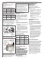 4
4
-
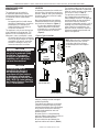 5
5
-
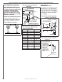 6
6
-
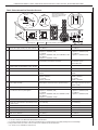 7
7
-
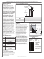 8
8
-
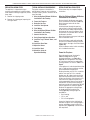 9
9
-
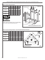 10
10
-
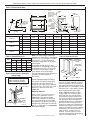 11
11
-
 12
12
-
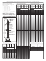 13
13
-
 14
14
-
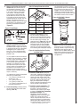 15
15
-
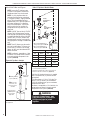 16
16
-
 17
17
-
 18
18
-
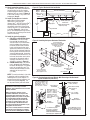 19
19
-
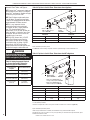 20
20
-
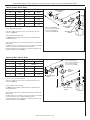 21
21
-
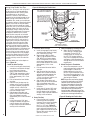 22
22
-
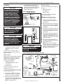 23
23
-
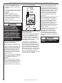 24
24
-
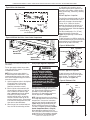 25
25
-
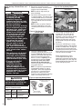 26
26
-
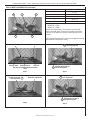 27
27
-
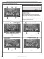 28
28
-
 29
29
-
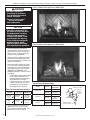 30
30
-
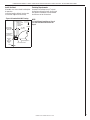 31
31
-
 32
32
-
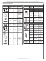 33
33
-
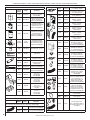 34
34
-
 35
35
-
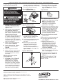 36
36


Astria Fireplaces MLDVT Guide d'installation
- Catégorie
- Cheminées
- Taper
- Guide d'installation
dans d''autres langues
Documents connexes

Autres documents
-
 Lennox Hearth ADAGIO-EN Manuel utilisateur
-
Lennox merit plus mpb3530cpm-b Manuel utilisateur
-
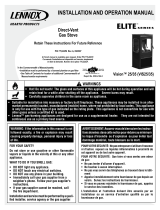 Lennox Hearth Gas Stove Manuel utilisateur
-
Superior Fireplaces BRT40ST Mode d'emploi
-
-
-
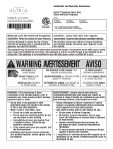 Astria EnvyCD40xxx series Installation And Operation Instructions Manual
-
-
Lennox LSBV-4228MN Manuel utilisateur
-
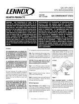 Lennox Hearth FGCK Manuel utilisateur


