Bradley S19-130BF Guide d'installation
- Catégorie
- Articles sanitaires
- Taper
- Guide d'installation

P.O. Box 309, Menomonee Falls, WI USA 53052-0309
PHONE 1-800-BRADLEY FAX (262) 251-5817
http://www.bradleycorp.com
Installation
215-1263 Rev. C; ECN 07-522
© 2007 Bradley Corporation
Page 1 of 5 8/27/07
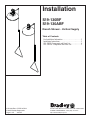
S19-130BF
S19-130ABF
Drench Shower - Vertical Supply
Table of Contents
Pre-Installation Information . . . . . . . . . . . . . . . . . . . . . 2
Installation Instructions. . . . . . . . . . . . . . . . . . . . . . . . . 3
S19-130BF Components and Parts List . . . . . . . . . . . . 4
S19-130ABF Components and Parts List. . . . . . . . . . . 5

2
S19-130BF, S19-130ABF Installation
8/27/07 Bradley Corporation • 215-1263 Rev. C; ECN 07-522
WARNING
Read this installation manual completely to ensure proper installation, then file it
with the owner or maintenance department. Compliance and conformity to drain
requirements and other local codes and ordinances is the responsibility of the installer.
Separate parts from packaging and make sure all parts are accounted for before
discarding any packaging material. If any parts are missing, do not begin installation
until you obtain the missing parts.
Flush the water supply lines before beginning installation and after installation is
complete. Test the unit for leaks and adequate water flow. Main water supply to the
eyewash should be “ON” at all times. Provisions shall be made to prevent unauthorized
shutoff.
The ANSI Z358.1 standard requires an uninterruptible supply of flushing fluid at a
minimum 30 PSI (0.21 MPa) flowing pressure. Flushing fluid should be tepid per ANSI
Z358.1.
The inspection and testing results of this equipment should be recorded weekly
to verify proper operation. This equipment should be inspected annually to ensure
compliance with ANSI Z358.1.
Workers who may come in contact with potentially hazardous materials should be
trained regarding the placement and proper operation of emergency equipment per
ANSI Z358.1.
For questions regarding the operation or installation of this product, visit www.
bradleycorp.com or call 1-800-BRADLEY.
Product warranties may also be found under ”Product Information” on our web site at
www.bradleycorp.com.
Installation
THIS
SIDE
UP
Packing List
•
•
•
•
P
.
O
.
B
o
x
3
0
9
,
M
e
n
o
m
o
n
e
e
F
a
ll
s
,
W
I 5
3
0
5
1
R
T
E
S
T
T
H
I
S
U
N
I
T
E
A
C
H
W
E
E
K
Test-o
perate v
alv
e(s) ea
c
h w
eek an
d sign
belo
w
.
R
eport an
y m
alfunction
s immed
iat
el
y
.
Ventil(e) w
öc
hen
tlic
h im
Testbe
trie
b
prüfen,
b
est
ätigt
durch U
ntersc
hrift. J
eglic
he S
törun
g s
of
or
t m
elden.
Date
Datum
Date
Signed
Unterschrift
Signe
Date
Date
Date
Signed
Signed
Signed
D
I
E
S
E
S
G
E
R
Ä
T
1
S
T
W
Ö
C
H
E
N
T
L
IC
H
Z
U
P
R
Ü
F
E
N
.
E
S
S
A
I
H
E
B
D
O
M
A
D
A
I
R
E
Test le
fonctio
nnem
ent d
es v
alv
es
chaque sem
aine et
sign
e en b
as. S
'il y
à quelqu
e c
ho
se qui n
e v
a p
as fait
un
rappor
t im
m
édiatem
ent.
P.O. BOX 309, MENOMONEE FALLS, WI 53052-0309 USA
TEL: 1-800-BRADLEY FAX: (262-251-5817)
http://www.bradleycorp.com
114-051

3
Installation S19-130BF, S19-130ABF
Bradley Corporation • 215-1263 Rev. C; ECN 07-522 8/27/07
Installation
Supplies Required:
• Teflon tape and pipe sealant
• Piping to 1" NPT water supply inlet
• Adequate supply pipe supports
• Minimum 4" (102 mm) drain to
accommodate 30 gallons per minute
discharge for drench shower waste
• Sign-mounting hardware
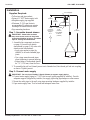
Step 1: Assemble drench shower
IMPORTANT: Some teflon sealants
may cause stress cracks in the plastic
showerhead leading to failure. Use teflon
tape for sealing the showerhead.
1. Assemble the components as shown
on page 4 (for units with plastic
showerhead) or page 5 (for units with
stainless steel showerhead).
• Apply pipe sealant or tape (by
installer) to all male-threaded pipe
joints.
• Use a strap wrench around pipes
when tightening to prevent marring.
• Bottom edge of showerhead should
be 7'-0" (2134 mm) from the floor.
2. To assemble the pull rod, thread jam nut on to threaded end, then thread pull rod into coupling
as shown. Tighten jam nut.
Step 2: Connect water supply
IMPORTANT: Do not rely on Bradley’s Drench Shower to support supply piping.
1. Connect water supply piping to 1" NPT inlet on unit (piping supplied by installer). Provide
adequate supports (supplied by installer) for supply pipe using pipe hangers or other means.
2. Mount the safety sign to the wall using sign-mounting hardware supplied by installer.
3. Open water supply lines. Test for leaks and adequate water flow.
1" IPS Supply
S19-130BF
Ø 10"
(254mm)
S19-130ABF
Ø 10-3/4"
(273mm)
7-1/4"
(184mm)
9"
(229mm)
7'-0"
(2134mm)
Suggested
Height to
Floor
9"
(229mm)
45"
(1142mm)

4
S19-130BF, S19-130ABF Installation
8/27/07 Bradley Corporation • 215-1263 Rev. C; ECN 07-522
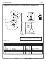
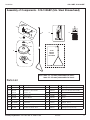
Assembly of Components - S19-130BF (Plastic Showerhead)
P.O. Box 309, Menomonee Falls, WI 53051
R
TEST THIS UNIT EACH WEEK
Test-operate valve(s) each week and sign below.
Report any malfunctions immediately.
Ventil(e) wöchentlich im Testbetrieb prüfen, bestätigt
durch Unterschrift. Jegliche Störung sofort melden.
Date
Datum
Date
Signed
Unterschrift
Signe
Date
Date
Date Signed
Signed
Signed
DIESES GERÄT 1ST WÖCHENTLICH ZU PRÜFEN.
ESSAI HEBDOMADAIRE
Test le fonctionnement des valves chaque semaine et
signe en bas. S'il y à quelque chose qui ne va pas fait
un rapport immédiatement.
P.O. BOX 309, MENOMONEE FALLS, WI 53052-0309 USA
TEL: 1-800-BRADLEY FAX: (262-251-5817)
http://www.bradleycorp.com
114-050
5
6
1.2
1.3
1.4
1.5
1.11
1.1
1
1" NPT
Supply Inlet
3
4
NOTE: Use
teflon tape
only.
4.3
4.2
4.1
2
ALIGN
HANDLE
PIECES
AS SHOWN
Parts List
1 S30-060 1 Stay-Open Ball Valve 1" NPT
1.1 S27-278 1 Ball Valve 1" with Jam Nut
1.11 110-214 1 Jam Nut only
1.2 140-720 1 Stop Bracket
1.3 124-048 1 Friction Washer
1.4 128-132 1 Handle
1.5 142-002DC 1 Lockwasher
2 S90-365D 1 Pull Rod - 45" Long
2.1 161-026 1 Hex Nut 1/4"-20 Stn. Steel
3 113-006LN 1 Pipe Nipple
4 S24-070 1 Plastic Showerhead Assembly
4.1 154-057 1 Plastic Showerhead Shell
4.2 155-005 1 Diffuser
4.3 160-245 3 Screw
5 114-050 1 Safety Sign
6 204-421 1 Emergency Inspection Tag
Item Part No. Qty Description
Item Part No. Qty Description
NOTE: Items 1.1–1.5 come preassembled as Item 1.
Items 4.1–4.3 come preassembled as Item 4.

5
Installation S19-130BF, S19-130ABF
Bradley Corporation • 215-1263 Rev. C; ECN 07-522 8/27/07
Assembly of Components - S19-130ABF (Stn. Steel Showerhead)
Parts List
1 S30-060 1 Stay-Open Ball Valve 1" NPT
1.1 S27-278 1 Ball Valve 1" with Jam Nut
1.11 110-214 1 Jam Nut only
1.2 140-720 1 Stop Bracket
1.3 124-048 1 Friction Washer
1.4 128-132 1 Handle
1.5 142-002DC 1 Lockwasher
2 S90-365D 1 Pull Rod - 45" Long
2.1 161-026 1 Hex Nut 1/4"-20 Stn. Steel
3 113-006LN 1 Pipe Nipple
4 S24-084 1 Stn. Steel Showerhead Assembly
4.1 187-053 1 Stn. Steel Showerhead Shell
4.2 155-008 1 Diffuser
4.3 160-138 2 Screw
4.4 125-001DP 1 Washer
4.5 153-312 1 Adapter, Celcon
5 114-050 1 Safety Sign
6 204-421 1 Emergency Inspection Tag
Item Part No. Qty Description
Item Part No. Qty Description
P.O. Box 309, Menomonee Falls, WI 53051
R
TEST THIS UNIT EACH WEEK
Test-operate valve(s) each week and sign below.
Report any malfunctions immediately.
Ventil(e) wöchentlich im Testbetrieb prüfen, bestätigt
durch Unterschrift. Jegliche Störung sofort melden.
Date
Datum
Date
Signed
Unterschrift
Signe
Date
Date
Date Signed
Signed
Signed
DIESES GERÄT 1ST WÖCHENTLICH ZU PRÜFEN.
ESSAI HEBDOMADAIRE
Test le fonctionnement des valves chaque semaine et
signe en bas. S'il y à quelque chose qui ne va pas fait
un rapport immédiatement.
P.O. BOX 309, MENOMONEE FALLS, WI 53052-0309 USA
TEL: 1-800-BRADLEY FAX: (262-251-5817)
http://www.bradleycorp.com
114-050
5
6
2
1.2
1.3
1.4
1.5
1.11
1.1
1
1" NPT
Supply Inlet
3
4
4.3
4.2
4.1
4.4
4.5
ALIGN
HANDLE
PIECES
AS SHOWN
NOTE: Items 1.1–1.5 come preassembled as Item 1.
Items 4.1–4.5 come preassembled as Item 4.
-
 1
1
-
 2
2
-
 3
3
-
 4
4
-
 5
5


Bradley S19-130BF Guide d'installation
- Catégorie
- Articles sanitaires
- Taper
- Guide d'installation
dans d''autres langues
- English: Bradley S19-130BF Installation guide
Documents connexes
-
Bradley S19-310BF Guide d'installation
-
-
-
-
-
-
-
-