ESAB Plasma Cutting System PAK 10 Manuel utilisateur
- Catégorie
- Système de soudage
- Taper
- Manuel utilisateur

Plasma Cutting
System
PAK 10
April 12, 2002 Manual No. 0-0515
Instruction Manual

WARNINGS
Read and understand this entire Manual and your employer’s safety practices before installing, oper-
ating, or servicing the equipment.
While the information contained in this Manual represents the Manufacturer's best judgement, the
Manufacturer assumes no liability for its use.
Plasma Cutting System PAK 10
Instruction Manual Number 0-0515
Published by:
Thermal Dynamics Corporation
82 Benning Street
West Lebanon, New Hampshire, USA 03784
(603) 298-5711
www.thermal-dynamics.com
Copyright 1984 by
Thermal Dynamics Corporation
All rights reserved.
Reproduction of this work, in whole or in part, without written per-
mission of the publisher is prohibited.
The publisher does not assume and hereby disclaims any liability to
any party for any loss or damage caused by any error or omission in
this Manual, whether such error results from negligence, accident, or
any other cause.
Printed in the United States of America
Publication Date: April 12, 2002
Record the following information for Warranty purposes:
Where Purchased:_________________________________________
Purchase Date:____________________________________________
Power Supply Serial #:_____________________________________
Torch Serial #:_____________________________________________

Contents
SECTION 1:
GENERAL INFORMATION ....................................................................................................i
1.01 Notes, Cautions and Warnings ..........................................................................i
1.02 Important Safety Precautions ............................................................................i
1.03 Publications......................................................................................................ii
1.04 Note, Attention et Avertissement .....................................................................iii
1.05 Precautions De Securite Importantes.............................................................. iii
1.06 Documents De Reference ............................................................................... v
1.07 Declaration of Conformity ............................................................................... vii
1.08 Statement of Warranty................................................................................... viii
SPECIFICATIONS ........................................................................................................................ 1
1.1. DESCRIPTION OF EQUIPMENT ................................................................... 2
1.2. SPECIFICATIONS........................................................................................... 2
1.3. PLASMA CUTTING........................................................................................ 3
1.4. THEORY OF OPERATION.............................................................................. 3
INSTALLATION............................................................................................................................. 5
2.1 UNPACKING ................................................................................................... 5
2.2 EQUIPMENT ASSEMBLY ............................................................................... 5
2.3 EQUIPMENT INSTALLATION ......................................................................... 6
OPERATION................................................................................................................................. 9
3.1 OPERATING CONTROLS............................................................................... 9
3.2 PRE-OPERATION SET-UP ............................................................................. 9
3.3 OPERATION ................................................................................................. 10
3.4 CUTTING CURRENT AND SPEED SELECTION......................................... 13
SERVICE.................................................................................................................................... 15
4.1 TORCH MAINTENANCE .............................................................................. 15
4.2 TORCH LEADS AND LEADS EXTENSION PACKAGES .............................. 17
4.3 PAK UNIT MAINTENANCE ........................................................................... 18
4.4 GAS PRESSURE REGULATORS ................................................................. 18
4.5 TROUBLE SHOOTING GUIDE ..................................................................... 19
4.6 TEST PROCEDURES................................................................................... 21
PARTS LISTS ............................................................................................................................. 25
General Arrangement............................................................................................ 25
PAK 10 Cutting System ......................................................................................... 26
Equipment Board Assembly .................................................................................. 28
Control P.C. Board Assembly................................................................................. 29
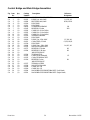
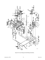
Control Bridge and Main Bridge Assemblies ......................................................... 30
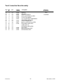
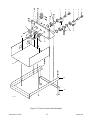
Torch Connection Panel Assembly ........................................................................ 32
Pilot Resistor and Rear Panel Assembly ............................................................... 34
Front Panel Assembly ........................................................................................... 36
Base Components Assembly ................................................................................ 38
Torch Leads, Leads Extension Packages, Torch Guide and
Circle Cutting Attachment, Remote Control Assembly .................................. 40
Series 4B Gas-Cooled Torches ............................................................................. 42
Gas Pressure Regulators...................................................................................... 44


Date: November 15, 2001 i GENERAL INFORMATION
SECTION 1:
GENERAL INFORMATION
1.01 Notes, Cautions and Warnings
Throughout this manual, notes, cautions, and warnings
are used to highlight important information. These high-
lights are categorized as follows:
NOTE
An operation, procedure, or background informa-
tion which requires additional emphasis or is help-
ful in efficient operation of the system.
CAUTION
A procedure which, if not properly followed, may
cause damage to the equipment.
WARNING
A procedure which, if not properly followed, may
cause injury to the operator or others in the oper-
ating area.
1.02 Important Safety Precautions
WARNINGS
OPERATION AND MAINTENANCE OF
PLASMA ARC EQUIPMENT CAN BE DAN-
GEROUS AND HAZARDOUS TO YOUR
HEALTH.
Plasma arc cutting produces intense electric and
magnetic emissions that may interfere with the
proper function of cardiac pacemakers, hearing
aids, or other electronic health equipment. Per-
sons who work near plasma arc cutting applica-
tions should consult their medical health profes-
sional and the manufacturer of the health
equipment to determine whether a hazard exists.
To prevent possible injury, read, understand and
follow all warnings, safety precautions and in-
structions before using the equipment. Call 1-603-
298-5711 or your local distributor if you have any
questions.
GASES AND FUMES
Gases and fumes produced during the plasma cutting
process can be dangerous and hazardous to your health.
• Keep all fumes and gases from the breathing area.
Keep your head out of the welding fume plume.
• Use an air-supplied respirator if ventilation is not
adequate to remove all fumes and gases.
• The kinds of fumes and gases from the plasma arc
depend on the kind of metal being used, coatings
on the metal, and the different processes. You must
be very careful when cutting or welding any met-
als which may contain one or more of the follow-
ing:
Antimony Chromium Mercury
Arsenic Cobalt Nickel
Barium Copper Selenium
Beryllium Lead Silver
Cadmium Manganese Vanadium
• Always read the Material Safety Data Sheets
(MSDS) that should be supplied with the material
you are using. These MSDSs will give you the in-
formation regarding the kind and amount of fumes
and gases that may be dangerous to your health.
• For information on how to test for fumes and gases
in your workplace, refer to item 1 in Subsection 1.03,
Publications in this manual.
• Use special equipment, such as water or down draft
cutting tables, to capture fumes and gases.
• Do not use the plasma torch in an area where com-
bustible or explosive gases or materials are located.
• Phosgene, a toxic gas, is generated from the vapors
of chlorinated solvents and cleansers. Remove all
sources of these vapors.
• This product, when used for welding or cutting,
produces fumes or gases which contain chemicals
known to the State of California to cause birth de-
fects and, in some cases, cancer. (California Health
& Safety Code Sec. 25249.5 et seq.)
ELECTRIC SHOCK
Electric Shock can injure or kill. The plasma arc process
uses and produces high voltage electrical energy. This
electric energy can cause severe or fatal shock to the op-
erator or others in the workplace.
• Never touch any parts that are electrically “live”
or “hot.”

GENERAL INFORMATION ii Date: November 15, 2001
• Wear dry gloves and clothing. Insulate yourself
from the work piece or other parts of the welding
circuit.
• Repair or replace all worn or damaged parts.
• Extra care must be taken when the workplace is
moist or damp.
• Install and maintain equipment according to NEC
code, refer to item 9 in Subsection 1.03, Publica-
tions.
• Disconnect power source before performing any
service or repairs.
• Read and follow all the instructions in the Operat-
ing Manual.
FIRE AND EXPLOSION
Fire and explosion can be caused by hot slag, sparks, or
the plasma arc.
• Be sure there is no combustible or flammable ma-
terial in the workplace. Any material that cannot
be removed must be protected.
• Ventilate all flammable or explosive vapors from
the workplace.
• Do not cut or weld on containers that may have
held combustibles.
• Provide a fire watch when working in an area where
fire hazards may exist.
• Hydrogen gas may be formed and trapped under
aluminum workpieces when they are cut under-
water or while using a water table. DO NOT cut
aluminum alloys underwater or on a water table
unless the hydrogen gas can be eliminated or dis-
sipated. Trapped hydrogen gas that is ignited will
cause an explosion.
NOISE
Noise can cause permanent hearing loss. Plasma arc pro-
cesses can cause noise levels to exceed safe limits. You
must protect your ears from loud noise to prevent per-
manent loss of hearing.
• To protect your hearing from loud noise, wear pro-
tective ear plugs and/or ear muffs. Protect others
in the workplace.
• Noise levels should be measured to be sure the deci-
bels (sound) do not exceed safe levels.
• For information on how to test for noise, see item 1
in Subsection 1.03, Publications, in this manual.
PLASMA ARC RAYS
Plasma Arc Rays can injure your eyes and burn your skin.
The plasma arc process produces very bright ultra violet
and infra red light. These arc rays will damage your
eyes and burn your skin if you are not properly protected.
• To protect your eyes, always wear a welding hel-
met or shield. Also always wear safety glasses with
side shields, goggles or other protective eye wear.
• Wear welding gloves and suitable clothing to pro-
tect your skin from the arc rays and sparks.
• Keep helmet and safety glasses in good condition.
Replace lenses when cracked, chipped or dirty.
• Protect others in the work area from the arc rays.
Use protective booths, screens or shields.
• Use the shade of lens as suggested in the following
per ANSI/ASC Z49.1:
Minimum Protective Suggested
Arc Current Shade No. Shade No.
Less Than 300* 8 9
300 - 400* 9 12
400 - 800* 10 14
* These values apply where the actual arc is clearly
seen. Experience has shown that lighter filters
may be used when the arc is hidden by the work-
piece.
1.03 Publications
Refer to the following standards or their latest revisions
for more information:
1. OSHA, SAFETY AND HEALTH STANDARDS, 29CFR
1910, obtainable from the Superintendent of Docu-
ments, U.S. Government Printing Office, Washington,
D.C. 20402
2. ANSI Standard Z49.1, SAFETY IN WELDING AND
CUTTING, obtainable from the American Welding So-
ciety, 550 N.W. LeJeune Rd, Miami, FL 33126
3. NIOSH, SAFETY AND HEALTH IN ARC WELDING
AND GAS WELDING AND CUTTING, obtainable
from the Superintendent of Documents, U.S. Govern-
ment Printing Office, Washington, D.C. 20402
4. ANSI Standard Z87.1, SAFE PRACTICES FOR OCCU-
PATION AND EDUCATIONAL EYE AND FACE PRO-
TECTION, obtainable from American National Stan-
dards Institute, 1430 Broadway, New York, NY 10018
5. ANSI Standard Z41.1, STANDARD FOR MEN’S
SAFETY-TOE FOOTWEAR, obtainable from the Ameri-
can National Standards Institute, 1430 Broadway, New
York, NY 10018

Date: November 15, 2001 iii GENERAL INFORMATION
6. ANSI Standard Z49.2, FIRE PREVENTION IN THE USE
OF CUTTING AND WELDING PROCESSES, obtain-
able from American National Standards Institute, 1430
Broadway, New York, NY 10018
7. AWS Standard A6.0, WELDING AND CUTTING CON-
TAINERS WHICH HAVE HELD COMBUSTIBLES, ob-
tainable from American Welding Society, 550 N.W.
LeJeune Rd, Miami, FL 33126
8. NFPA Standard 51, OXYGEN-FUEL GAS SYSTEMS
FOR WELDING, CUTTING AND ALLIED PRO-
CESSES, obtainable from the National Fire Protection
Association, Batterymarch Park, Quincy, MA 02269
9. NFPA Standard 70, NATIONAL ELECTRICAL CODE,
obtainable from the National Fire Protection Associa-
tion, Batterymarch Park, Quincy, MA 02269
10. NFPA Standard 51B, CUTTING AND WELDING PRO-
CESSES, obtainable from the National Fire Protection
Association, Batterymarch Park, Quincy, MA 02269
11. CGA Pamphlet P-1, SAFE HANDLING OF COM-
PRESSED GASES IN CYLINDERS, obtainable from the
Compressed Gas Association, 1235 Jefferson Davis
Highway, Suite 501, Arlington, VA 22202
12. CSA Standard W117.2, CODE FOR SAFETY IN WELD-
ING AND CUTTING, obtainable from the Canadian
Standards Association, Standards Sales, 178 Rexdale
Boulevard, Rexdale, Ontario, Canada M9W 1R3
13. NWSA booklet, WELDING SAFETY BIBLIOGRAPHY
obtainable from the National Welding Supply Associa-
tion, 1900 Arch Street, Philadelphia, PA 19103
14. American Welding Society Standard AWSF4.1, RECOM-
MENDED SAFE PRACTICES FOR THE PREPARA-
TION FOR WELDING AND CUTTING OF CONTAIN-
ERS AND PIPING THAT HAVE HELD HAZARDOUS
SUBSTANCES, obtainable from the American Welding
Society, 550 N.W. LeJeune Rd, Miami, FL 33126
15. ANSI Standard Z88.2, PRACTICE FOR RESPIRATORY
PROTECTION, obtainable from American National
Standards Institute, 1430 Broadway, New York, NY
10018
1.04 Note, Attention et
Avertissement
Dans ce manuel, les mots “note,” “attention,” et
“avertissement” sont utilisés pour mettre en relief des
informations à caractère important. Ces mises en relief
sont classifiées comme suit :
NOTE
Toute opération, procédure ou renseignement
général sur lequel il importe d’insister davantage
ou qui contribue à l’efficacité de fonctionnement
du système.
ATTENTION
Toute procédure pouvant résulter
l’endommagement du matériel en cas de non-
respect de la procédure en question.
AVERTISSEMENT
Toute procédure pouvant provoquer des blessures
de l’opérateur ou des autres personnes se trouvant
dans la zone de travail en cas de non-respect de la
procédure en question.
1.05 Precautions De Securite
Importantes
AVERTISSEMENTS
L’OPÉRATION ET LA MAINTENANCE DU
MATÉRIEL DE SOUDAGE À L’ARC AU JET
DE PLASMA PEUVENT PRÉSENTER DES
RISQUES ET DES DANGERS DE SANTÉ.
Coupant à l’arc au jet de plasma produit de l’énergie
électrique haute tension et des émissions
magnétique qui peuvent interférer la fonction
propre d’un “pacemaker” cardiaque, les appareils
auditif, ou autre matériel de santé electronique.
Ceux qui travail près d’une application à l’arc au
jet de plasma devrait consulter leur membre
professionel de médication et le manufacturier de
matériel de santé pour déterminer s’il existe des
risques de santé.
Il faut communiquer aux opérateurs et au person-
nel TOUS les dangers possibles. Afin d’éviter les
blessures possibles, lisez, comprenez et suivez tous
les avertissements, toutes les précautions de sécurité
et toutes les consignes avant d’utiliser le matériel.
Composez le + 603-298-5711 ou votre distributeur
local si vous avez des questions.
FUMÉE et GAZ
La fumée et les gaz produits par le procédé de jet de
plasma peuvent présenter des risques et des dangers de
santé.

GENERAL INFORMATION iv Date: November 15, 2001
• Eloignez toute fumée et gaz de votre zone de respira-
tion. Gardez votre tête hors de la plume de fumée
provenant du chalumeau.
• Utilisez un appareil respiratoire à alimentation en air
si l’aération fournie ne permet pas d’éliminer la fumée
et les gaz.
• Les sortes de gaz et de fumée provenant de l’arc de
plasma dépendent du genre de métal utilisé, des
revêtements se trouvant sur le métal et des différents
procédés. Vous devez prendre soin lorsque vous
coupez ou soudez tout métal pouvant contenir un ou
plusieurs des éléments suivants:
antimoine cadmium mercure
argent chrome nickel
arsenic cobalt plomb
baryum cuivre sélénium
béryllium manganèse vanadium
• Lisez toujours les fiches de données sur la sécurité
des matières (sigle américain “MSDS”); celles-ci
devraient être fournies avec le matériel que vous
utilisez. Les MSDS contiennent des renseignements
quant à la quantité et la nature de la fumée et des gaz
pouvant poser des dangers de santé.
• Pour des informations sur la manière de tester la
fumée et les gaz de votre lieu de travail, consultez
l’article 1 et les documents cités à la page 5.
• Utilisez un équipement spécial tel que des tables de
coupe à débit d’eau ou à courant descendant pour
capter la fumée et les gaz.
• N’utilisez pas le chalumeau au jet de plasma dans une
zone où se trouvent des matières ou des gaz combus-
tibles ou explosifs.
• Le phosgène, un gaz toxique, est généré par la fumée
provenant des solvants et des produits de nettoyage
chlorés. Eliminez toute source de telle fumée.
• Ce produit, dans le procéder de soudage et de coupe,
produit de la fumée ou des gaz pouvant contenir des
éléments reconnu dans L’état de la Californie, qui
peuvent causer des défauts de naissance et le cancer.
(La sécurité de santé en Californie et la code sécurité
Sec. 25249.5 et seq.)
CHOC ELECTRIQUE
Les chocs électriques peuvent blesser ou même tuer. Le
procédé au jet de plasma requiert et produit de l’énergie
électrique haute tension. Cette énergie électrique peut
produire des chocs graves, voire mortels, pour l’opérateur
et les autres personnes sur le lieu de travail.
• Ne touchez jamais une pièce “sous tension” ou “vive”;
portez des gants et des vêtements secs. Isolez-vous
de la pièce de travail ou des autres parties du circuit
de soudage.
• Réparez ou remplacez toute pièce usée ou
endommagée.
• Prenez des soins particuliers lorsque la zone de tra-
vail est humide ou moite.
• Montez et maintenez le matériel conformément au
Code électrique national des Etats-Unis. (Voir la page
5, article 9.)
• Débranchez l’alimentation électrique avant tout tra-
vail d’entretien ou de réparation.
• Lisez et respectez toutes les consignes du Manuel de
consignes.
INCENDIE ET EXPLOSION
Les incendies et les explosions peuvent résulter des scories
chaudes, des étincelles ou de l’arc de plasma. Le procédé
à l’arc de plasma produit du métal, des étincelles, des
scories chaudes pouvant mettre le feu aux matières com-
bustibles ou provoquer l’explosion de fumées
inflammables.
• Soyez certain qu’aucune matière combustible ou in-
flammable ne se trouve sur le lieu de travail. Protégez
toute telle matière qu’il est impossible de retirer de la
zone de travail.
• Procurez une bonne aération de toutes les fumées
inflammables ou explosives.
• Ne coupez pas et ne soudez pas les conteneurs ayant
pu renfermer des matières combustibles.
• Prévoyez une veille d’incendie lors de tout travail dans
une zone présentant des dangers d’incendie.
• Le gas hydrogène peut se former ou s’accumuler sous
les pièces de travail en aluminium lorsqu’elles sont
coupées sous l’eau ou sur une table d’eau. NE PAS
couper les alliages en aluminium sous l’eau ou sur
une table d’eau à moins que le gas hydrogène peut
s’échapper ou se dissiper. Le gas hydrogène accumulé
explosera si enflammé.
RAYONS D’ARC DE PLASMA
Les rayons provenant de l’arc de plasma peuvent blesser
vos yeux et brûler votre peau. Le procédé à l’arc de
plasma produit une lumière infra-rouge et des rayons

Date: November 15, 2001 v GENERAL INFORMATION
ultra-violets très forts. Ces rayons d’arc nuiront à vos
yeux et brûleront votre peau si vous ne vous protégez
pas correctement.
• Pour protéger vos yeux, portez toujours un casque ou
un écran de soudeur. Portez toujours des lunettes de
sécurité munies de parois latérales ou des lunettes de
protection ou une autre sorte de protection oculaire.
• Portez des gants de soudeur et un vêtement protecteur
approprié pour protéger votre peau contre les
étincelles et les rayons de l’arc.
• Maintenez votre casque et vos lunettes de protection
en bon état. Remplacez toute lentille sale ou
comportant fissure ou rognure.
• Protégez les autres personnes se trouvant sur la zone
de travail contre les rayons de l’arc en fournissant des
cabines ou des écrans de protection.
• Utilisez la nuance de lentille qui est suggèrée dans le
recommendation qui suivent ANSI/ASC Z49.1:
Nuance Minimum Nuance Suggerée
Courant Arc Protective Numéro Numéro
Moins de 300* 8 9
300 - 400* 9 12
400 - 800* 10 14
* Ces valeurs s’appliquent ou l’arc actuel est observé
clairement. L’experience a démontrer que les filtres
moins foncés peuvent être utilisés quand l’arc est
caché par moiceau de travail.
BRUIT
Le bruit peut provoquer une perte permanente de l’ouïe.
Les procédés de soudage à l’arc de plasma peuvent
provoquer des niveaux sonores supérieurs aux limites
normalement acceptables. Vous dú4ez vous protéger les
oreilles contre les bruits forts afin d’éviter une perte
permanente de l’ouïe.
• Pour protéger votre ouïe contre les bruits forts, portez
des tampons protecteurs et/ou des protections
auriculaires. Protégez également les autres personnes
se trouvant sur le lieu de travail.
• Il faut mesurer les niveaux sonores afin d’assurer que
les décibels (le bruit) ne dépassent pas les niveaux
sûrs.
• Pour des renseignements sur la manière de tester le
bruit, consultez l’article 1, page 5.
1.06 Documents De Reference
Consultez les normes suivantes ou les révisions les plus
récentes ayant été faites à celles-ci pour de plus amples
renseignements :
1. OSHA, NORMES DE SÉCURITÉ DU TRAVAIL ET DE
PROTECTION DE LA SANTÉ, 29CFR 1910,
disponible auprès du Superintendent of Documents,
U.S. Government Printing Office, Washington, D.C.
20402
2. Norme ANSI Z49.1, LA SÉCURITÉ DES
OPÉRATIONS DE COUPE ET DE SOUDAGE,
disponible auprès de la Société Américaine de
Soudage (American Welding Society), 550 N.W.
LeJeune Rd., Miami, FL 33126
3. NIOSH, LA SÉCURITÉ ET LA SANTÉ LORS DES
OPÉRATIONS DE COUPE ET DE SOUDAGE À
L’ARC ET AU GAZ, disponible auprès du Superin-
tendent of Documents, U.S. Government Printing
Office, Washington, D.C. 20402
4. Norme ANSI Z87.1, PRATIQUES SURES POUR LA
PROTECTION DES YEUX ET DU VISAGE AU TRA-
VAIL ET DANS LES ECOLES, disponible de l’Institut
Américain des Normes Nationales (American Na-
tional Standards Institute), 1430 Broadway, New York,
NY 10018
5. Norme ANSI Z41.1, NORMES POUR LES
CHAUSSURES PROTECTRICES, disponible auprès
de l’American National Standards Institute, 1430
Broadway, New York, NY 10018
6. Norme ANSI Z49.2, PRÉVENTION DES INCENDIES
LORS DE L’EMPLOI DE PROCÉDÉS DE COUPE ET
DE SOUDAGE, disponible auprès de l’American Na-
tional Standards Institute, 1430 Broadway, New York,
NY 10018
7. Norme A6.0 de l’Association Américaine du Soudage
(AWS), LE SOUDAGE ET LA COUPE DE
CONTENEURS AYANT RENFERMÉ DES PRODUITS
COMBUSTIBLES, disponible auprès de la American
Welding Society, 550 N.W. LeJeune Rd., Miami, FL
33126
8. Norme 51 de l’Association Américaine pour la Pro-
tection contre les Incendies (NFPA), LES SYSTEMES
À GAZ AVEC ALIMENTATION EN OXYGENE
POUR LE SOUDAGE, LA COUPE ET LES
PROCÉDÉS ASSOCIÉS, disponible auprès de la Na-
tional Fire Protection Association, Batterymarch Park,
Quincy, MA 02269

GENERAL INFORMATION vi Date: November 15, 2001
9. Norme 70 de la NFPA, CODE ELECTRIQUE NA-
TIONAL, disponible auprès de la National Fire Pro-
tection Association, Batterymarch Park, Quincy, MA
02269
10. Norme 51B de la NFPA, LES PROCÉDÉS DE
COUPE ET DE SOUDAGE, disponible auprès de la
National Fire Protection Association, Batterymarch
Park, Quincy, MA 02269
11. Brochure GCA P-1, LA MANIPULATION SANS
RISQUE DES GAZ COMPRIMÉS EN CYLINDRES,
disponible auprès de l’Association des Gaz
Comprimés (Compressed Gas Association), 1235
Jefferson Davis Highway, Suite 501, Arlington, VA
22202
12. Norme CSA W117.2, CODE DE SÉCURITÉ POUR
LE SOUDAGE ET LA COUPE, disponible auprès
de l’Association des Normes Canadiennes, Stan-
dards Sales, 178 Rexdale Boulevard, Rexdale,
Ontario, Canada, M9W 1R3
13.Livret NWSA, BIBLIOGRAPHIE SUR LA
SÉCURITÉ DU SOUDAGE, disponible auprès de
l’Association Nationale de Fournitures de Soudage
(National Welding Supply Association), 1900 Arch
Street, Philadelphia, PA 19103
14. Norme AWSF4.1 de l’Association Américaine de
Soudage, RECOMMANDATIONS DE PRATIQUES
SURES POUR LA PRÉPARATION À LA COUPE ET
AU SOUDAGE DE CONTENEURS ET TUYAUX
AYANT RENFERMÉ DES PRODUITS
DANGEREUX , disponible auprès de la American
Welding Society, 550 N.W. LeJeune Rd., Miami, FL
33126
15. Norme ANSI Z88.2, PRATIQUES DE PROTECTION
RESPIRATOIRE, disponible auprès de l’American
National Standards Institute, 1430 Broadway, New
York, NY 10018

Date: November 15, 2001 vii GENERAL INFORMATION
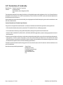
1.07 Declaration of Conformity
Manufacturer: Thermal Dynamics Corporation
Address: 82 Benning Street
West Lebanon, New Hampshire 03784
USA
The equipment described in this manual conforms to all applicable aspects and regulations of the ‘Low Voltage Directive’
(European Council Directive 73/23/EEC as amended by Council Directive 93/68/EEC) and to the National legislation for
the enforcement of this Directive.
Serial numbers are unique with each individual piece of equipment and details description, parts used to manufacture a unit
and date of manufacture.
National Standard and Technical Specifications
The product is designed and manufactured to a number of standards and technical requirements. Among them are:
* CSA (Canadian Standards Association) standard C22.2 number 60 for Arc welding equipment.
* UL (Underwriters Laboratory) rating 94VO flammability testing for all printed-circuit boards used.
* ISO/IEC 60974-1 (BS 638-PT10) (EN 60 974-1) (EN50192) (EN50078) applicable to plasma cutting equipment and associ-
ated accessories.
* Extensive product design verification is conducted at the manufacturing facility as part of the routine design and manufac-
turing process. This is to ensure the product is safe, when used according to instructions in this manual and related
industry standards, and performs as specified. Rigorous testing is incorporated into the manufacturing process to ensure
the manufactured product meets or exceeds all design specifications.
Thermal Dynamics has been manufacturing products for more than 30 years, and will continue to achieve excellence in our
area of manufacture.
Manufacturers responsible representative: Giorgio Bassi
Managing Director
Thermal Dynamics Europe
Via rio Fabbiani 8A
40067 Rastignano (BO)
Italy

GENERAL INFORMATION viii Date: November 15, 2001
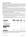
1.08 Statement of Warranty
LIMITED WARRANTY: Thermal Dynamics
®
Corporation (hereinafter “Thermal”) warrants that its products will be free of defects in
workmanship or material. Should any failure to conform to this warranty appear within the time period applicable to the Thermal
products as stated below, Thermal shall, upon notification thereof and substantiation that the product has been stored, installed, operated,
and maintained in accordance with Thermal’s specifications, instructions, recommendations and recognized standard industry practice,
and not subject to misuse, repair, neglect, alteration, or accident, correct such defects by suitable repair or replacement, at Thermal’s sole
option, of any components or parts of the product determined by Thermal to be defective.
THIS WARRANTY IS EXCLUSIVE AND IS IN LIEU OF ANY WARRANTY OF MERCHANTABILITY OR FITNESS FOR A
PARTICULAR PURPOSE.
LIMITATION OF LIABILITY: Thermal shall not under any circumstances be liable for special or consequential damages, such as, but
not limited to, damage or loss of purchased or replacement goods, or claims of customers of distributor (hereinafter “Purchaser”) for
service interruption. The remedies of the Purchaser set forth herein are exclusive and the liability of Thermal with respect to any
contract, or anything done in connection therewith such as the performance or breach thereof, or from the manufacture, sale, delivery,
resale, or use of any goods covered by or furnished by Thermal whether arising out of contract, negligence, strict tort, or under any
warranty, or otherwise, shall not, except as expressly provided herein, exceed the price of the goods upon which such liability is based.
THIS WARRANTY BECOMES INVALID IF REPLACEMENT PARTS OR ACCESSORIES ARE USED WHICH MAY IMPAIR THE
SAFETY OR PERFORMANCE OF ANY THERMAL PRODUCT.
THIS WARRANTY IS INVALID IF THE PRODUCT IS SOLD BY NON-AUTHORIZED PERSONS.
The limited warranty periods for Thermal products shall be as follows (with the exception of XL Plus Series, CutMaster Series , Cougar
and DRAG-GUN): A maximum of three (3) years from date of sale to an authorized distributor and a maximum of two (2) years from
date of sale by such distributor to the Purchaser, and with the further limitations on such two (2) year period (see chart below).
The limited warranty period for XL Plus Series and CutMaster Series shall be as follows: A maximum of four (4) years from date
of sale to an authorized distributor and a maximum of three (3) years from date of sale by such distributor to the Purchaser, and
with the further limitations on such three (3) year period (see chart below).
The limited warranty period for Cougar and DRAG-GUN shall be as follows: A maximum of two (2) years from date of sale to an
authorized distributor and a maximum of one (1) year from date of sale by such distributor to the Purchaser, and with the further
limitations on such two (2) year period (see chart below).
Parts
XL Plus & Parts Parts
PAK Units, Power Supplies CutMaster Series Cougar/Drag-Gun All Others Labor
Main Power Magnetics 3 Years 1 Year 2 Years 1 Year
Original Main Power Rectifier 3 Years 1 Year 2 Years 1 Year
Control PC Board 3 Years 1 Year 2 Years 1 Year
All Other Circuits And Components Including, 1 Year 1 Year 1 Year 1 Year
But Not Limited To, Starting Circuit,
Contactors, Relays, Solenoids, Pumps,
Power Switching Semi-Conductors
Consoles, Control Equipment, Heat 1 Year 1 Year 1 Year
Exchanges, And Accessory Equipment
Torch And Leads
Maximizer 300 Torch 1 Year 1 Year
SureLok Torches 1 Year 1 Year 1 Year
All Other Torches 180 Days 180 Days 180 Days 180 Days
Repair/Replacement Parts 90 Days 90 Days 90 Days None
Warranty repairs or replacement claims under this limited warranty must be submitted by an authorized Thermal Dynamics® repair
facility within thirty (30) days of the repair. No transportation costs of any kind will be paid under this warranty. Transportation
charges to send products to an authorized warranty repair facility shall be the responsibility of the customer. All returned goods shall
be at the customer’s risk and expense. This warranty supersedes all previous Thermal warranties.
Effective November 15, 2001

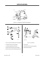
Manual No. 0-0515 1 Specifications
Pak 10
Gas
Regulators
Gas Hoses
Spare Parts
Kit
Work Cable
Torch and Leads
A-03289
4
3
1
2
A-03290
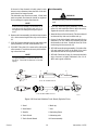
Figure 1-A Components of PAK 10 Cutting System
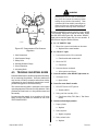
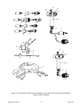
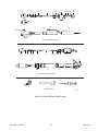
Fig. 1-B Type 4B LO-AMP Gas Cooled Torches
1. 90° Hand cutting torch (PCH-4B 90°)
2. 70° Hand cutting torch (PCH-4B 70°)
3. Machine mounted cutting torch (PCM-4BT)
4. Remote control unit for machine mounted torch
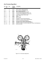
Fig. 1-C Accessories
1. Cylinder Rack
2. Torch Guide & Circle Cutting Attachment
3. Leads Extension Package
SPECIFICATIONS
Th
erm
al A
rc P
A
K
10
3
1
2
A-03291

Specifications 2 Manual No. 0-0515
1.1. DESCRIPTION OF
EQUIPMENT
A complete PAK 10 system includes a PCH-4B hand
torch and/or PCM-4BT machine torch with 25 foot or
50 foot (7.62 m or 15.24 m) leads, a spare parts kit, a
PAK 10, gas supply, pressure regulators, 10 foot gas
supply hoses and a 25 foot work cable with clamp.
Three 4B torches are available (Figure 1-B): 90° hand
torch (1), 70° hand torch (2), and a machine mounted
torch (3). The 4BT machine mounted torch is controlled
by a remote control assembly (4, Figure 1-B) with an
ON/OFF switch and a remote current control. An ini-
tial supply of parts for the 4B is in the spare parts kit
(Figure 1-A).
1.2. SPECIFICATIONS
TYPE 4B GAS COOLED TORCH
• Current Rating: 100 amperes maximum, DCSP, 80%
duty cycle
• Plasma Gas: Nitrogen (N2), 30 psi (2.2 kg/cm
2
), 15
SCFH (7.5 lpm); 65% Argon/35% Hydrogen, 40 psi
(2.8 kg/cm
2
), 30 SCFH
• Secondary Gas: Carbon dioxide (C0
2
), 50 psi (3.52
kg/cm
2
), 250 SCFH (125 lpm); compressed air, 50
psi (3.52 kg/cm
2
), 250 SCFH (125 lpm)
• Cutting Capacity (most metals): Maximum thick-
ness- 1 inch (25.4 mm); production cutting- 5/8 inch
(15.9 mm); piercing- 3/4 inch (19 mm)
• Weight: Hand torch PCH-4B- 1-3/4 lbs. (0.79 kg);
Machine mounted torch PCM-4BT- 3 lbs. (1.36 kg)
without leads
PAK 10 UNIT
Power Input: 20 KVA, 50/60 Hertz, 3-phase in one of
the following standard voltage/amperage combina-
tions:
1- 208/230/460 volts, 60/50/25 amps
2- 230/460/575 volts, 50/25/20 amps
3- 380/415/460 volts, 30/30/25 amps
4- 380/460/500 volts, 30/25/25 amps
5- 220/380/500 volts, 50/30/25 amps
6- 180/200/220 volts, 70/60/50 amps
Certain other special voltage combinations are avail-
able.
• Rated Output: 100 amperes DC straight polarity
• Current Control: 50 to 100 amps continuously ad-
justed by feedback circuit
• Control Circuit: 24 volt AC
• Plasma and Secondary Gas Pressures: Controlled
by pressure regulator at gas supply
• Weight: 615 lbs. (279 kg)
• Dimensions: Width- 26 inches (66 cm); Depth- 36
inches (91 cm); Height- 24 inches (61 cm)
ACCESSORIES AVAILABLE:
• A cylinder rack (1, Figure 1-C) that holds two gas
cylinders
• A torch guide and circle cutting attachment (2, Fig-
ure 1-C)
• Torch lead extension packages to extend the torch
leads in increments of 25 or 50 feet (3, Figure 1-C)
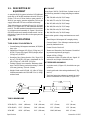
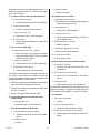
TORCH DIMENSIONS
AB CD
PCH-4B (70°) 16.00” (406 mm) 3.98” (100 mm) 1.25” (32 mm) 1.32” (34 mm)
PCH-4B (90°) 15.25” (390 mm) 3.98” (100 mm) 1.25” (32 mm) 1.32” (34 mm)
PCM-4BT 18.38” (467 mm) 8.12” (206 mm) 16.00” (406 mm) 0.69” (17 mm)
A
B
C
D
A
B MIN
C MAX
D
A-03292

Manual No. 0-0515 3 Specifications
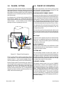
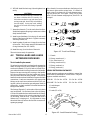
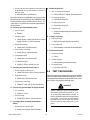
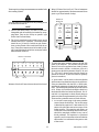
1.3. PLASMA CUTTING
Plasma is a gas which has been heated to an extremely
high temperature and ionized so that the gas becomes
electrically conductive. The plasma cutting process uses
this plasma to transfer an electric arc to the workpiece.
The metal to be cut is melted by the heat of the arc and
then blown away.
In a plasma torch, a cool gas such as nitrogen (N2) en-
ters in Zone A, Figure 1-D. In Zone B a pilot arc be-
tween the electrode and the front of the torch heats and
ionizes the gas. An arc transfers to the workpiece
through a column of plasma gas in Zone C.
A-00002
Workpiece
Power
Supply
+
_
C
B
A
Figure 1-D Plasma Torch Operation
Plasma torches deliver a high concentration of heat to
a very small area. The stiff, constricted plasma arc is
shown in Zone C. Direct current straight polarity is
used for plasma cutting, as shown in the illustration.
Plasma cutting torches use a secondary gas, which as-
sists the high velocity plasma gas in blowing the mol-
ten metal out of the cut. This results in fast, clean, dross
(slag)-free cuts. In the PAK l0 system, the secondary
gas also cools the cutting torch. CO
2
or compressed air,
supplied by either a cylinder or plant air system, is nor-
mally used as the secondary gas.
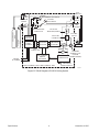
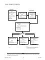
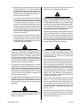
1.4. THEORY OF OPERATION
The main components of the PAK 10 cutting system
are illustrated in the block diagram (Figure 1-E) and
their function is summarized below.
PLASMA AND SECONDARY GASES
Plasma and secondary gases flow through the PAK unit
to the cutting torch at pressures set at the external regu-
lators. The pressure of each gas is indicated on the front
panel gauges. Solenoid valves turn the gases on and
off. The gas pressure interlocks shut the system down
if the plasma gas pressure falls below 25 psi (1.7 bar) or
the secondary gas pressure drops below 30 psi (2.0 bar).
The plasma gas flows through the green/black lead,
around the electrode and gas distributor, and out
through the tip orifice.
The secondary gas flows through the red/yellow torch
lead, down the outside of the torch liner, through the
holes at the base of the liner and out around the plasma
arc.
PILOT ARC
When the torch is started, the pilot arc contactor closes
and an arc is established between the electrode and
cutting tip. The pilot arc makes a path for transferring
the main arc to the work.
HIGH FREQUENCY
Because direct current alone is not sufficient to strike
and maintain the pilot arc, high frequency is superim-
posed on the direct current.
CUTTING ARC
The main bridge rectifier converts the 3-phase AC
power to DC power for the pilot and main cutting arcs.
The negative output is connected to the torch electrode
through the torch lead. The positive output is connected
to the workpiece (through the work cable) and, through
a contactor and resistor to the torch tip.
CURRENT CONTROL
The desired cutting current is set on the CURRENT
ADJUST knob. A control circuit stabilizes cutting cur-
rent against fluctuations due to changes in line volt-
ages, material thickness, torch standoff and travel
speed. Changing the amount of saturating current in
the reactor changes the amount of AC power supplied
to the main bridge rectifier. The amount of saturating
current is controlled by a comparator which compares
the actual cutting current to the amperage selector po-
tentiometer setting.

Specifications 4 Manual No. 0-0515
Figure 1-E Block Diagram of PAK 10 Cutting System
GAS PRESSURE
INTERLOCK
POWER
TRANS-
FORMER
SATURABLE
REACTOR
COMPARATOR
PILOT ARC
HIGH FREQUENCY
PILOT ARC
CONTACTOR
AMPERAGE
SELECTOR POT
SOLENOID
VALVES
SECONDARY
GAS
PLASMA
GAS
3-PHASE
AC POWER
CONTROL
CIRCUITS
SECONDARY GAS PRESS
PLASMA
GAS PRESS
MAIN BRIDGE
RECTIFIER
MAIN
CONTACTOR
SCR CONTROL
BRIDGE
RECTIFIER
WORK
CURRENT
SENSING COIL
(TOROID
TRANSFORMER)
PAK 10 POWER SUPPLY AND CONTROL UNIT
AMP
POS.
(RED/YEL)
TORCH
LEADS
CUTTING
TORCH
(-)
(+)
SHUNT
A-03293
NEG.
(GR/BLK)

Manual No. 0-0515 5 Installation
INSTALLATION
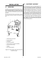
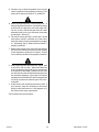
2.1 UNPACKING
The PAK 10 is skid-mounted and protected with a car-
ton and padding material to prevent damage in ship-
ment. The casters, lifting eye, gas hoses, work cable,
torch, torch leads and miscellaneous parts are packed
separately.
One copy of the PAK 10 Instruction Manual, in a trans-
parent plastic envelope, is packed in with the PAK 10
unit.
3
5
4
1
2
6
7
8
A-03356
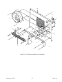
1. Washer-head cover screws
2. Cover Assembly
3. Lifting eye
4. Access door fasteners
5. Lead connection access door assembly
6. Interlock switch actuator
7. Casters
8. Work cable receptacle
Figure 2-A Power Supply and Control Unit with
Access Door Open
2.2 EQUIPMENT ASSEMBLY
After removing the carton, turn the lifting eye (3,
Fig. 2-A) all the way into the threaded socket on top
of the unit and tighten it securely. The lifting eye
may then be used to lift the unit for removal of the
skids and installation of the casters (7). If no crane
or hoist is available for lifting, a fork lift or jack may
be used. Use care so that the base of the unit will
not be damaged. Lift the unit and remove the two
skids which are secured to the base assembly with
four bolts and hex nuts. Install the two swivel cast-
ers (7) at the front of the unit using four 5/16-18 x
3/4 inch cap screws and four 5/16-18 locknuts in
each. Install the two fixed casters at the rear in the
same manner. Lower the unit onto the casters and
remove the lifting device.

Installation 6 Manual No. 0-0515
2.3 EQUIPMENT INSTALLATION
Select a clean, dry location with good ventilation and
adequate working space. Be sure that the air flow into
the unit (from underneath) and out the back is not ob-
structed. A source of 3 phase power and a source of
gases with pressure regulators are required.
Review PRECAUTIONS in the first section of this
manual to be sure that location meets all safety require-
ments.
Most users prefer nitrogen (N2) as the plasma gas and
carbon dioxide (C0
2
) as the secondary gas, since it is
easy to obtain good quality cuts with this combination.
Argon/Hydrogen (Ar/H
2
) (65% argon-35% hydrogen)
is sometimes preferred as the plasma gas when cutting
1/2" to 1" thick aluminum to improve cut finish and
reduce smoke and fumes. Compressed air (free of dirt
and oil) may also be used as the secondary gas.
1
A-03357
Figure 2-B Internal Packing Material
NOTE
A typical 50 lb. CO
2
cylinder is capable of deliv-
ering 35 SCFH on a continuous basis. There-
fore, the manifolding of several CO
2
cylinders
may be necessary to obtain the required torch flow
rate, depending on application and duty cycle.
Connect the unit as follows:
1. Remove the top of the unit as follows:
a. Remove the screws holding the cover.
b. Open the lead connection access door (5, Fig-
ure 2-A).
c. Lift off the cover of the unit.
2. Remove the paper band (1, Figure 2-B) stapled
around the main terminal board.
3. Check for possible loose connections and damage
that may have occurred during shipment.
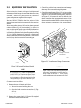
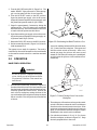
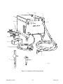
4. Check the transformer (Figure 2-C) to be sure that
it is set up for the available power. Three terminals
(Figure 2-C) are provided for each phase. As shown
in Figure 2-C, to connect the unit for 460 volts, the
three wires from the input terminals attach to the
three terminals marked 460. For other voltages, the
three wires are connected to the appropriately
marked terminals.
Voltage Connections -
Transformer
A-03358
Figure 2-C Transformer Voltage Connections
CAUTION
Input voltage of the available three phase power
source must correspond to one of the three oper-
ating voltages of the PAK 10. If not properly
connected, damage to the equipment may result.

Manual No. 0-0515 7 Installation
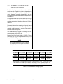
5. Check the three phase power service to be used.
Recommended fuse or circuit breaker sizes are given
in Table 2-A.
Power
Trans-
former
Line
Voltages
Accepted
Fuse or
Circuit
Breaker
Amperes
Recommended
Minimum
Primary
Wire size *
1
208
230
460
80
60
30
4
6
10
2
230
460
575
60
30
25
6
10
10
3
380
415
460
40
40
30
8
10
10
4
380
460
500
40
30
30
8
10
10
5
220
380
500
60
40
30
6
8
10
6
180
200
220
90
80
60
4
6
6
* From the National Electric Code, 1978
Table 2-A Line Voltages, Circuit Protection &
Recommended Wire Size
NOTE
Larger wires may be required if the length is over
25 feet.
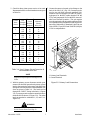
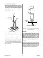
6. With the primary power disconnect switch open,
connect the electrical ground and primary power
leads to the terminals on the upper right hand side
(facing the unit from the front.) Recommended wire
sizes are given in Table 2-A. The leads are led
through the “INPUT” fitting in the back (1, Figure
2-E). A proper ground connection must be made to
the brass stud as shown (2, Figure 2-D). The other
leads are attached to terminals L1, L2, and L3 (1,
Figure 2-D).
WARNING
Do Not Turn on Power Until Step 10.
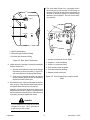
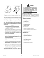
7. Connect the gases to be used to the fittings on the
back of the unit (2 & 3, Fig. 2-E). Pressure regula-
tors for use with PAK units and specifically cali-
brated for use with nitrogen (Cat. #9-2722), argon/
hydrogen (Cat. #9-3053), carbon dioxide (Cat. #9-
2759), and compressed air (Cat. #9-3022) are avail-
able from Thermal Dynamics. The gas supplies
must be equipped with adjustable pressure regula-
tors capable of being set between 0 and 60 psi (0-4.1
bar) and of delivering 15 Standard Cubic Feet per
Hour (SCFH) (7 lpm) of N2 and 250 SCFH (118 lpm)
of C0
2
or compressed air.
1
2
A-03359
1. Primary Lead Terminals
2. Ground Terminal
Figure 2-D Primary Lead Connections

Installation 8 Manual No. 0-0515
4FU
5A
INPUT
PLASMA
SEC
3
1
2
A-03360
1. INPUT cable bushing
2. SECondary gas connection fitting
3. PLASMA gas connection fitting
Figure 2-E Rear Panel Connections
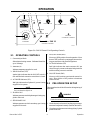
8. Check the torch to see that it is properly assembled
(Refer to Section 4.1.).
a. Pass the torch leads and control wire through
the bushing on the front panel (5, Figure 2-F)
and connect them to the appropriate fittings.
b. If the torch is machine-mounted, the remote
control assembly plug must also be inserted in
the remote current control jack.
9. Re-install the cover of the unit (the leads access door
must be open). Start the sheet metal screws but do
not tighten them until the cover is lined up.
Carefully close the leads access door, making sure
that the switch actuator (1, Figure 2-F) enters its slot
and activates the interlock switch. When the cover
is properly positioned, tighten the screws.
WARNING
Do Not Operate the Unit unless all parts of the
enclosure are in place. This is important for
proper cooling as well as safety.
10. The work cable (Figure 1-A) is equipped with a
twist-lock plug on one end and a work clamp on
the other. The plug fits into the work receptacle on
the front of the unit (8, Figure 2-A) and the clamp
attaches to the workpiece. The unit is now ready
for operation.
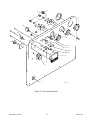
3
5
4
1
2
6
A-03361
l. Actuator for Interlock Switch (SW3)
2. Negative (-) torch lead fitting
3. Positive (+) torch lead fitting
4. Torch control switch receptacle
5. Torch lead insulating bushing
6. Remote current control jack
Figure 2-F Torch Connection Access Door and
Panel
La page est en cours de chargement...
La page est en cours de chargement...
La page est en cours de chargement...
La page est en cours de chargement...
La page est en cours de chargement...
La page est en cours de chargement...
La page est en cours de chargement...
La page est en cours de chargement...
La page est en cours de chargement...
La page est en cours de chargement...
La page est en cours de chargement...
La page est en cours de chargement...
La page est en cours de chargement...
La page est en cours de chargement...
La page est en cours de chargement...
La page est en cours de chargement...
La page est en cours de chargement...
La page est en cours de chargement...
La page est en cours de chargement...
La page est en cours de chargement...
La page est en cours de chargement...
La page est en cours de chargement...
La page est en cours de chargement...
La page est en cours de chargement...
La page est en cours de chargement...
La page est en cours de chargement...
La page est en cours de chargement...
La page est en cours de chargement...
La page est en cours de chargement...
La page est en cours de chargement...
La page est en cours de chargement...
La page est en cours de chargement...
La page est en cours de chargement...
La page est en cours de chargement...
La page est en cours de chargement...
La page est en cours de chargement...
-
 1
1
-
 2
2
-
 3
3
-
 4
4
-
 5
5
-
 6
6
-
 7
7
-
 8
8
-
 9
9
-
 10
10
-
 11
11
-
 12
12
-
 13
13
-
 14
14
-
 15
15
-
 16
16
-
 17
17
-
 18
18
-
 19
19
-
 20
20
-
 21
21
-
 22
22
-
 23
23
-
 24
24
-
 25
25
-
 26
26
-
 27
27
-
 28
28
-
 29
29
-
 30
30
-
 31
31
-
 32
32
-
 33
33
-
 34
34
-
 35
35
-
 36
36
-
 37
37
-
 38
38
-
 39
39
-
 40
40
-
 41
41
-
 42
42
-
 43
43
-
 44
44
-
 45
45
-
 46
46
-
 47
47
-
 48
48
-
 49
49
-
 50
50
-
 51
51
-
 52
52
-
 53
53
-
 54
54
-
 55
55
-
 56
56


ESAB Plasma Cutting System PAK 10 Manuel utilisateur
- Catégorie
- Système de soudage
- Taper
- Manuel utilisateur
dans d''autres langues
Documents connexes
-
 Firepower Plasma Cutting Power Supply Firepower™ PC-800 Manuel utilisateur
-
 Firepower Plasma Cutting Power Supply Firepower PC-500 Manuel utilisateur
-
 Firepower Plasma Cutting Power Supply Firepower FP-55 Manuel utilisateur
-
 Thermal Arc Inverter Arc Welder Model 400S Manuel utilisateur
-
 Thermal Dynamics PakMaster™ 100 XL™ Plus Air Plasma Cutting Power Supply Manuel utilisateur
-
 Thermal Dynamics PakMaster™ 100 XL™ Plus Air Plasma Cutting Power Supply Manuel utilisateur
-
 Thermal Dynamics PakMaster™ 75 XL™ Plus Air Plasma Cutting Power Supply Manuel utilisateur
-
 Thermal Arc Inverter Arc Welder Model LM300 CC/CV Manuel utilisateur
-
 Thermal Arc Inverter Arc Welder Model 400GTS CC/Tig Manuel utilisateur
-
 Thermal Dynamics 38 CUTMASTER™ Plasma Cutting System Manuel utilisateur


