Marvel MP30RA2LP Guide d'installation
- Catégorie
- Frigos
- Taper
- Guide d'installation

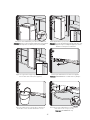
Installation
Instructions
Built-In
All Refrigerator
All Freezer
MP30RA2
MP36RA2
MP30FA2
MP36FA2

2
Table of Contents
Warnings & Important Information
_ _ _ _ _ _ _ _ _ _ _ _ _ _ _ _ _ _ _ _ _ _ _ _ _ _ _ _ _ _ _ _ _ _ _ _ _ _ _ _ _ _ _ _ _ _ _ _ _ _ _ _ _ _ _ _ _
2
Professional
D i m e n s i o n s & S p e c i f i c a t i o n s ( 3 0 ” & 3 6 ” ) _ _ _ _ _ _ _ _ _ _ _ _ _ _ _ _ _ _ _ _ _ _ _ _ _ _ _ _ _ _ _ _ _ _ _ _ _ _ _ _ _ _ _ 4
D i m e n s i o n s & S p e c i f i c a t i o n s ( 3 0 ” & 3 6 ” w i t h f l u s h m o u n t t r i m ) _ _ _ _ _ _ _ _ _ _ _ _ _ _ _ _ _ _ _ _ _ _ _ 6
C u t o u t D i m e n s i o n s ( 3 0 ” ) _ _ _ _ _ _ _ _ _ _ _ _ _ _ _ _ _ _ _ _ _ _ _ _ _ _ _ _ _ _ _ _ _ _ _ _ _ _ _ _ _ _ _ _ _ _ _ _ _ _ _ _ _ _ _ _ _ 8
A n t i - T i p D i m e n s i o n s ( 3 0 ” ) _ _ _ _ _ _ _ _ _ _ _ _ _ _ _ _ _ _ _ _ _ _ _ _ _ _ _ _ _ _ _ _ _ _ _ _ _ _ _ _ _ _ _ _ _ _ _ _ _ _ _ _ _ _ _ _ 9
C u t o u t D i m e n s i o n s ( 3 6 ” ) _ _ _ _ _ _ _ _ _ _ _ _ _ _ _ _ _ _ _ _ _ _ _ _ _ _ _ _ _ _ _ _ _ _ _ _ _ _ _ _ _ _ _ _ _ _ _ _ _ _ _ _ _ _ _ _ 1 0
A n t i - T i p D i m e n s i o n s ( 3 6 ” ) _ _ _ _ _ _ _ _ _ _ _ _ _ _ _ _ _ _ _ _ _ _ _ _ _ _ _ _ _ _ _ _ _ _ _ _ _ _ _ _ _ _ _ _ _ _ _ _ _ _ _ _ _ _ _ 1 1
D i m e n s i o n s & S p e c i f i c a t i o n s ( D u a l 3 0 ” / D u a l 3 0 ” & 3 6 ” ) _ _ _ _ _ _ _ _ _ _ _ _ _ _ _ _ _ _ _ _ _ _ _ _ _ _ _ _ 1 2
Dimensions & Specifications (Dual 30”/ Dual 30” & 36” with flush mount trim) _ _ _ _ _ _ _ _ _ 16
C u t o u t D i m e n s i o n s ( D u a l 3 0 ” ) _ _ _ _ _ _ _ _ _ _ _ _ _ _ _ _ _ _ _ _ _ _ _ _ _ _ _ _ _ _ _ _ _ _ _ _ _ _ _ _ _ _ _ _ _ _ _ _ _ _ _ _ 2 0
A n t i - T i p D i m e n s i o n s ( D u a l 3 0 ” ) _ _ _ _ _ _ _ _ _ _ _ _ _ _ _ _ _ _ _ _ _ _ _ _ _ _ _ _ _ _ _ _ _ _ _ _ _ _ _ _ _ _ _ _ _ _ _ _ _ _ _ 2 1
C u t o u t D i m e n s i o n s ( D u a l 3 0 ” & 3 6 ” ) _ _ _ _ _ _ _ _ _ _ _ _ _ _ _ _ _ _ _ _ _ _ _ _ _ _ _ _ _ _ _ _ _ _ _ _ _ _ _ _ _ _ _ _ _ _ 2 2
A n t i - T i p D i m e n s i o n s ( D u a l 3 0 ” & 3 6 ” ) _ _ _ _ _ _ _ _ _ _ _ _ _ _ _ _ _ _ _ _ _ _ _ _ _ _ _ _ _ _ _ _ _ _ _ _ _ _ _ _ _ _ _ _ _ 2 3
C u t o u t D i m e n s i o n s ( D u a l 3 6 ” ) _ _ _ _ _ _ _ _ _ _ _ _ _ _ _ _ _ _ _ _ _ _ _ _ _ _ _ _ _ _ _ _ _ _ _ _ _ _ _ _ _ _ _ _ _ _ _ _ _ _ _ _ 2 4
A n t i - T i p D i m e n s i o n s ( D u a l 3 6 ” ) _ _ _ _ _ _ _ _ _ _ _ _ _ _ _ _ _ _ _ _ _ _ _ _ _ _ _ _ _ _ _ _ _ _ _ _ _ _ _ _ _ _ _ _ _ _ _ _ _ _ _ 2 5
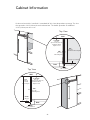
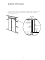
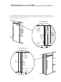
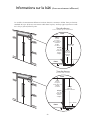
Cabinet Information _ _ _ _ _ _ _ _ _ _ _ _ _ _ _ _ _ _ _ _ _ _ _ _ _ _ _ _ _ _ _ _ _ _ _ _ _ _ _ _ _ _ _ _ _ _ _ _ _ _ _ _ _ _ _ _ _ _ _ _ 2 6
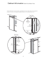
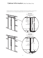
Cabinet Information (with flush mount trim) _ _ _ _ _ _ _ _ _ _ _ _ _ _ _ _ _ _ _ _ _ _ _ _ _ _ _ _ _ _ _ _ _ _ _ _ _ _ _ _ 28
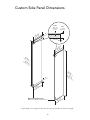
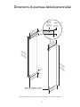
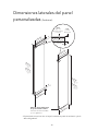
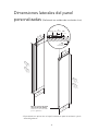
Custom Side Panel Dimensions _ _ _ _ _ _ _ _ _ _ _ _ _ _ _ _ _ _ _ _ _ _ _ _ _ _ _ _ _ _ _ _ _ _ _ _ _ _ _ _ _ _ _ _ _ _ _ _ _ _ _ _ _ _ 3 0
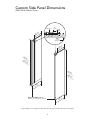
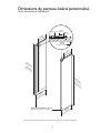
Custom Side Panel Dimensions (with flush mount trim)_ _ _ _ _ _ _ _ _ _ _ _ _ _ _ _ _ _ _ _ _ _ _ _ _ _ _ _ _ _ _ _ _ _ 31
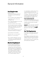
General Information _ _ _ _ _ _ _ _ _ _ _ _ _ _ _ _ _ _ _ _ _ _ _ _ _ _ _ _ _ _ _ _ _ _ _ _ _ _ _ _ _ _ _ _ _ _ _ _ _ _ _ _ _ _ _ _ _ _ _ _ _ _ _ _ 3 3
U n p a c k i n g & M o v i n g _ _ _ _ _ _ _ _ _ _ _ _ _ _ _ _ _ _ _ _ _ _ _ _ _ _ _ _ _ _ _ _ _ _ _ _ _ _ _ _ _ _ _ _ _ _ _ _ _ _ _ _ _ _ _ _ _ _ _ _ 3 4
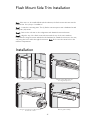
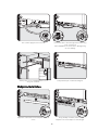
F l u s h M o u n t S i d e Tr i m I n s t a l l a t i o n _ _ _ _ _ _ _ _ _ _ _ _ _ _ _ _ _ _ _ _ _ _ _ _ _ _ _ _ _ _ _ _ _ _ _ _ _ _ _ _ _ _ _ _ _ _ _ _ _ _ _ _ 3 5
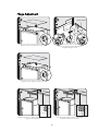
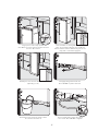
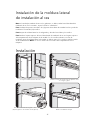
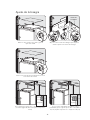
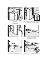
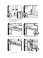
I n s t a l l a t i o n _ _ _ _ _ _ _ _ _ _ _ _ _ _ _ _ _ _ _ _ _ _ _ _ _ _ _ _ _ _ _ _ _ _ _ _ _ _ _ _ _ _ _ _ _ _ _ _ _ _ _ _ _ _ _ _ _ _ _ _ _ _ _ _ _ _ _ _ _ _ _ _ _ 3 5
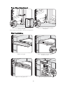
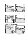
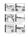
H i n g e A d j u s t m e n t _ _ _ _ _ _ _ _ _ _ _ _ _ _ _ _ _ _ _ _ _ _ _ _ _ _ _ _ _ _ _ _ _ _ _ _ _ _ _ _ _ _ _ _ _ _ _ _ _ _ _ _ _ _ _ _ _ _ _ _ _ _ 3 6
K i c k p l a t e I n s t a l l a t i o n _ _ _ _ _ _ _ _ _ _ _ _ _ _ _ _ _ _ _ _ _ _ _ _ _ _ _ _ _ _ _ _ _ _ _ _ _ _ _ _ _ _ _ _ _ _ _ _ _ _ _ _ _ _ _ _ _ _ _ _ 3 8
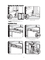
Door Stop Adjustment _ _ _ _ _ _ _ _ _ _ _ _ _ _ _ _ _ _ _ _ _ _ _ _ _ _ _ _ _ _ _ _ _ _ _ _ _ _ _ _ _ _ _ _ _ _ _ _ _ _ _ _ _ _ _ _ _ _ 3 9
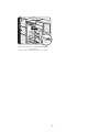
F i n a l I n s t a l l a t i o n _ _ _ _ _ _ _ _ _ _ _ _ _ _ _ _ _ _ _ _ _ _ _ _ _ _ _ _ _ _ _ _ _ _ _ _ _ _ _ _ _ _ _ _ _ _ _ _ _ _ _ _ _ _ _ _ _ _ _ _ _ _ _ _ 3 9
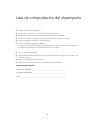
Performance Checklist _ _ _ _ _ _ _ _ _ _ _ _ _ _ _ _ _ _ _ _ _ _ _ _ _ _ _ _ _ _ _ _ _ _ _ _ _ _ _ _ _ _ _ _ _ _ _ _ _ _ _ _ _ _ _ _ _ _ _ _ _ _ 4 1
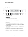
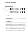
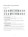
C o n t r o l P a n e l s _ _ _ _ _ _ _ _ _ _ _ _ _ _ _ _ _ _ _ _ _ _ _ _ _ _ _ _ _ _ _ _ _ _ _ _ _ _ _ _ _ _ _ _ _ _ _ _ _ _ _ _ _ _ _ _ _ _ _ _ _ _ _ _ _ _ _ _ _ 4 2
Service & Registration_ _ _ _ _ _ _ _ _ _ _ _ _ _ _ _ _ _ _ _ _ _ _ _ _ _ _ _ _ _ _ _ _ _ _ _ _ _ _ _ _ _ _ _ _ _ _ _ _ _ _ _ _ _ _ _ _ _ _ _ _ _ _ 4 3
Your safety and the safety of others is very important.
We have provided many important safety
messages in this manual and on your appliance. Always read and obey all
safety messages.
This is the safety alert symbol. This symbol alerts you to hazards that
can kill or hurt you and others.
All safety messages will be preceded by the safety alert symbol and the word“DANGER”
or “WARNING.”These words mean:
DANGER
You will be killed or seriously injured if you don’t follow instructions.
WARNING
You can be killed or seriously injured if you don’t follow instructions.
All safety messages will identify the hazard, tell you how to reduce the chance of injury,
and tell you what can happen if the instructions are not followed.

3
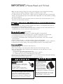
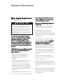
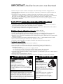
IMPORTANT–Please Read and Follow!
• Make sure that incoming voltage is the same as unit rating. An electric rating plate specifying
voltage, frequency, wattage, amperage, and phase is attached to the product.
• To reduce the risk of fire, electric shock, or injury to persons, installation work and electrical wiring
must be done by qualified people in accordance with all applicable codes and standards, including
fire-rated construction.
• The installer should leave these instructions with the consumer who should retain them for local
inspector’s use and for future reference.
A GFI
shall be used if required by NFPA-70 (National Electric Code), federal/state/local laws, or
local ordinances.
• The required use of a GFI is normally related to the location of a receptacle with respect to
any significant sources of water or moisture.
• Viking Range, LLC will NOT warranty any problems resulting from GFI outlets which are not
installed properly or do not meet the requirements below.
If the use of a GFI is required
, it should be:
• Of the receptacle type (breaker type or portable type NOT recommended)
• Used with permanent wiring only (temporary or portable wiring NOT recommended)
• On a dedicated circuit (no other receptacles, switches or loads in the circuit)
• Connected to a standard breaker of appropriate size (GFI breaker of the same size NOT
recommended)
• Rated for Class A (5 mA +/- 1 mA trip current) as per UL 943 standard)
• In good condition and free from any loose-fitting gaskets (if applicable in outdoor situations)
• Protected from moisture (water, steam, high humidity) as much as reasonably possible
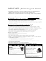
WARNING
ELECTRICAL SHOCK
HAZARD
Disconnect power or turn power
disconnect switch to OFF position
before removing
top grille. Failure to do so can
result in death or electrical shock.
WARNING
TIP OVER HAZARD
Appliance is top
heavy and tips easily
when not completely
installed. Keep doors
closed until appliance
is completely installed
and secured per installation instructions.
Use two or more people to move and
install appliance. Failure to do so can
result in death or serious injury.
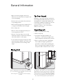
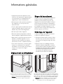
Most of the unit’s weight is at the top. Extra care is
needed when moving the unit to prevent
tipping. Use cardboard shipping material or
plywood under unit until it is installed in the
operating position to protect floor surface.
It is your responsibility to:
• comply with installation specifications and dimensions.
• properly install unit.
• remove any moldings or decorative panels that prevent the unit from being serviced.
• make sure that you have these materials (not provided with your unit), which are necessary
for proper installation:
• 1/4” (6 mm) copper tubing with shutoff valve
• 6– #8 x 3” (7.6 cm) wood screws (longer screws may be required)
• 1– Saddle valve (do not use self-piercing feature of the valve)
• assure that floor will support unit, door panels and contents (approximately 1200 pounds [540 kg]).
• provide a properly grounded electrical outlet.
• assure that location will permit appliance doors to open 90° minimum.

24”
(61.0 cm)
35”
(88.9 cm)
75–15/16”
(192.9 cm)
3–19/32”
(9.1 cm)
)
36”
36”
(91.5 cm)
(
91.5
cm
)
36”
(91.5 cm)
26”
(66.0 cm)
9–5/32”
(23.3 cm)
82–3/4”
(210.2 cm)
min.
to
84–1/16”
(213.5 cm)
max.
2
0–3/
4
”
(52.7 cm)
22–3/16”
(56.4 cm)
24”
(61.0 cm)
29”
(73.7 cm)
75–15/16”
(192.9 cm
)
3–19/32”
(9.1 cm)
30”
30”
(76.2 cm)
(76.2 cm)
30”
(76.2 cm)
9–5/32”
(23.3 cm)
82–3/4”
(210.2 cm)
min.
to
84–1/16”
(213.5 cm)
max.
2
0–3/4
”
(52.7 cm)
22–3/16”
(56.4 cm)
26”
(66.0 cm)
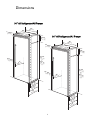
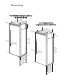
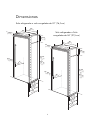
4
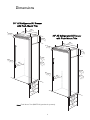
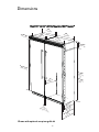
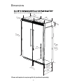
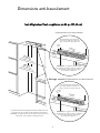
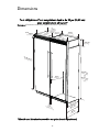
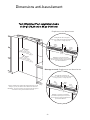
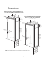
30” All Refrigerator/All Freezer
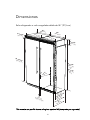
36” All Refrigerator/All Freezer
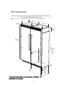
Dimensions

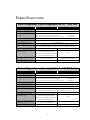
5
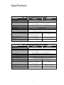
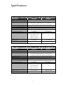
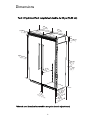
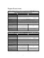
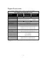
30” All Refrigerator/All Freezer
Description MP30FA2 MP30RA2
Overall width 30” (76.2 cm)
Overall height from bottom 82-3/4” (210.2 cm) min. to 84-1/16” (213.5 cm) max.
Overall depth from rear To front edge of side trim: 22-3/16” (56.4 cm)
To front of top grille: 24” (61.0 cm)
To front of handle endcap: 26” (66.0 cm)
Cutout width 29-5/8” (75.2 cm) min. to 29-3/4” (75.6 cm) max.
Cutout height 82-7/8” (210.5 cm) min. to 84-1/16” (213.5 cm) max.
Cutout depth 24” (61.0 cm) min.
Electrical requirements 115 volt, 60 Hz, 15 amp dedicated circuit; 3-wire cord with
grounded 3-prong plug attached to product
Maximum amp usage 9.1 amps 5.7 amps
Inlet water requirements 1/4” copper tubing inlet
waterline; minimum 20 psi; N/A
maximum 120 psi
Overall interior dimensions
Total capacity 15.9 cu. ft. (450 liters) 17.8 cu. ft. (504 liters)
Approximate shipping weight 550 lbs. (247.5 kg) 525 lbs. (236.3 kg)
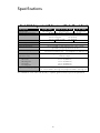
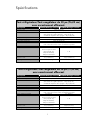
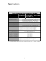
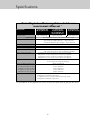
36” All Refrigerator/All Freezer
Description MP36FA2 MP36RA2
Overall width 36” (91.5 cm)
Overall height from bottom 82-3/4” (210.2 cm) min. to 84-1/16” (213.5 cm) max.
Overall depth from rear To front edge of side trim: 22-3/16” (56.4 cm)
To front of top grille: 24” (61.0 cm)
To front of handle endcap: 26” (66.0 cm)
Cutout width 35-5/8” (90.5 cm) min. to 35-3/4” (90.8 cm) max.
Cutout height 82-7/8” (210.5 cm) min. to 84-1/16” (213.5 cm) max.
Cutout depth 24” (61.0 cm) min.
Electrical requirements 115 volt, 60 Hz, 15 amp dedicated circuit; 3-wire cord with
grounded 3-prong plug attached to product
Maximum amp usage 9.5 amps 6.5 amps
Inlet water requirements 1/4” copper tubing inlet
waterline; minimum 20 psi; N/A
maximum 120 psi
Overall interior dimensions
Total capacity 19.2 cu. ft. (544 liters) 22.0 cu. ft. (623 liters)
Approximate shipping weight 605 lbs. (272.3 kg) 590 lbs. (265.5 kg)
Specifications

24”
(61.0 cm)
35”
(88.9 cm)
75–15/16”
(192.9 cm)
3–19/32”
(9.1 cm)
36”
36”
(91.5 cm)
(91
.5 cm)
36”
(91.5 cm)
26”
(66.0 cm)
9–5/32”
(23.3 cm)
82–3/4”
(210.2 cm)
min.
to
84–1/16”
(213.5 cm)
max.
2
0–3/4
”
(52.7 cm)
23–3/8”
(59.4 cm)
24”
(61.0 cm)
29”
(73.7 cm)
75–15/16”
(192.9 cm
)
3–19/32”
(9.1 cm)
30”
30”
(76.2 cm)
(76.2 cm)
30”
(76.2 cm)
9–5/32”
(23.3 cm)
82–3/4”
(210.2 cm)
min.
to
84–1/16”
(213.5 cm)
max.
2
0–3/4
”
(52.7 cm)
23–3/8”
(59.4 cm)
26”
(66.6 cm)
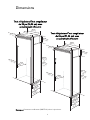
6
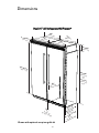
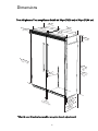
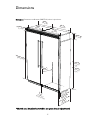
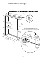
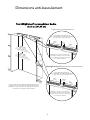
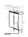
30” All Refrigerator/All Freezer
with Flush Mount Trim
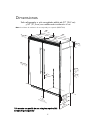
36” All Refrigerator/All Freezer
with Flush Mount Trim
Note: Flush Mount Trim (PBIRFTKSS) purchased separately.
Dimensions

7
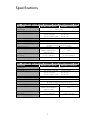
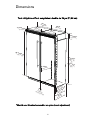
30” All Refrigerator/All Freezer with Flush Mount Trim
Description MP30FA2 Flush Mount MP30RA2 Flush Mount
Overall width 30” (76.2 cm)
Overall height from bottom 82-3/4” (210.2 cm) min. to 84-1/16” (213.5 cm) max.
Overall depth from rear To front edge of side trim: 23-3/8” (59.4 cm)
To front of top grille: 24” (61.0 cm)
To front of handle endcap: 26” (66.0 cm)
Cutout width 30” (74.9 cm)
Cutout height 82-7/8” (210.5 cm) min. to 84-1/16” (213.5 cm) max.
Cutout depth 24” (61.0 cm) min.
Electrical requirements 115 volt, 60 Hz, 15 amp dedicated circuit; 3-wire cord with
grounded 3-prong plug attached to product
Maximum amp usage 9.1 amps 5.7 amps
Inlet water requirements 1/4” copper tubing inlet
waterline; minimum 20 psi; N/A
maximum 120 psi
Overall interior dimensions
Total capacity 15.9 cu. ft. (450 liters) 17.8 cu. ft. (504 liters)
Approximate shipping weight 550 lbs. (247.5 kg) 525 lbs. (236.3 kg)
36” All Refrigerator/All Freezer with Flush Mount Trim
Description MP36FA2 Flush Mount MP36RA2 Flush Mount
Overall width 36” (91.5 cm)
Overall height from bottom 82-3/4” (210.2 cm) min. to 84-1/16” (213.5 cm) max.
Overall depth from rear To front edge of side trim: 23-3/8” (59.4 cm)
To front of top grille: 24” (61.0 cm)
To front of handle endcap: 26” (66.0 cm)
Cutout width 36” (91.4 cm)
Cutout height 82-7/8” (210.5 cm) min. to 84-1/16” (213.5 cm) max.
Cutout depth 24” (61.0 cm) min.
Electrical requirements 115 volt, 60 Hz, 15 amp dedicated circuit; 3-wire cord with
grounded 3-prong plug attached to product
Maximum amp usage 9.5 amps 6.5 amps
Inlet water requirements 1/4” copper tubing inlet
waterline; minimum 20 psi; N/A
maximum 120 psi
Overall interior dimensions
Total capacity 19.2 cu. ft. (544 liters) 22.0 cu. ft. (623 liters)
Approximate shipping weight 605 lbs. (272.3 kg) 590 lbs. (265.5 kg)
Specifications

9”
(22.9 cm)
73–3/8”
(186.4 cm)
82–7/8”
(210.5 cm) min.
anti-tip board &
opening height
84–1/16”
(213.5 cm) max.
anti-tip board &
opening height
29–5/8”
(75.2 cm) min.
to
29-3/4”
(75.6 cm) max.
3
0”
(76.
2 cm)
Flush Mount only
24”
(61.0 cm)
Electric Outlet Location
Water Line Entry Area
Note: Shown for All Freezer Only
29–5/8”
(75.2 cm)
6–3/4”
(17.1 cm)
7–5/8”
(19.4 cm)
3”
(7.6 cm)
5/8”
(1.5 cm)
5/8”
(1.5 cm)
10–1/2”
(26.7 cm)
5/8”
(1.5 cm)
10–3/4”
(27.3 cm)
1”
(2.5 cm)
3–5/8”
(9.2 cm)
Optional floor
water line entry
30”
(76.2 cm)
Flush Mount only
See Anti-Tip board installation
6”
(15.2 cm)
9”
(22.9 cm)
8
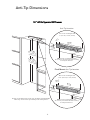
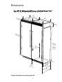
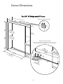
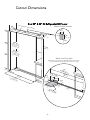
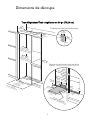
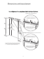
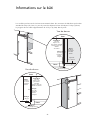
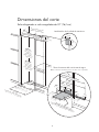
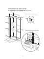
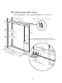
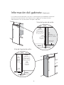
30” All Refrigerator/All Freezer
Cutout Dimensions

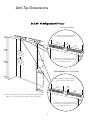
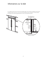
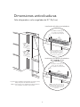
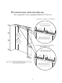
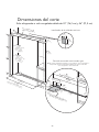
Bottom of anti-tip board is 3–7/8” (9.8 cm) below opening height.
Note: Top of unit must be placed firmly under anti-tip board.
Anti-Tip Location
Flush Mount Anti-Tip Location
NOTE: If unit is installed deeper than
24” (61.0 cm),then shim behind the mounting
board by the difference.
NOTE: If unit is installed deeper than
24” (61.0 cm), then shim behind the mounting
board by the difference.
Two 2”x 4” mounting boards
3” (7.6 cm) x 3-1/2” (8.9 cm)
One 2”x 4” mounting board
1–1/2” (3.8 cm) x 3-1/2” (8.9 cm)
79–3/8”
(201.6 cm) min.
to bottom of
anti-tip board
80–1/2”
(204.6 cm) max.
to bottom of
anti-tip board
23”
(58.4 cm)
3–1/2”
(8.9 cm)
3”
(7.6 cm)
23”
(58.4 cm)
3–1/2”
(8.9 cm)
1–1/2”
(3.8 cm)
9
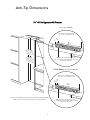
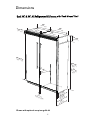
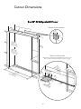
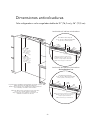
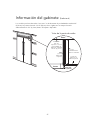
30” All Refrigerator/All Freezer
Anti-Tip Dimensions

9”
(22.9 cm)
73–3/8”
(186.4 cm)
82–7/8”
(210.5 cm) min.
anti-tip board &
opening height
84–1/16”
(213.5 cm) max.
anti-tip board &
opening height
35–5/8”
(90.5 cm) min.
to
35-3/4”
(90.8 cm) max.
36”
(9
1.4 cm)
Flush Mount only
24”
(61.0 cm)
Electric Outlet Location
Water Line Entry Area
Note: Shown for All Freezer Only
35–5/8”
(90.5 cm)
6–3/4”
(17.1 cm)
7–5/8”
(19.4 cm)
3”
(7.6 cm)
5/8”
(1.5 cm)
5/8”
(1.5 cm)
10–1/2”
(26.7 cm)
5/8”
(1.5 cm)
10–3/4”
(27.3 cm)
1”
(2.5 cm)
3–5/8”
(9.2 cm)
Optional floor
water line entry
36”
(91.4 cm)
Flush Mount only
See Anti-Tip board installation
6”
(15.2 cm)
9”
(22.9 cm)
10
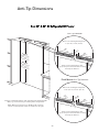
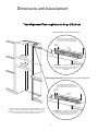
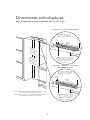
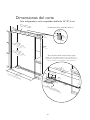
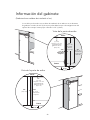
36” All Refrigerator/All Freezer
Cutout Dimensions

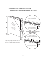
Bottom of anti-tip board is 3–7/8” (9.8 cm) below opening height.
Note: Top of unit must be placed firmly under anti-tip board.
79–3/8”
(201.6 cm) min.
to bottom of
anti-tip board
80–1/2”
(204.6 cm) max.
to bottom of
anti-tip board
Anti-Tip Location
Flush Mount Anti-Tip Location
NOTE: If unit is installed deeper than
24” (61.0 cm), then shim behind the mounting
board by the difference.
NOTE: If unit is installed deeper than
24” (61.0 cm), then shim behind the mounting
board by the difference.
Two 2”x 4” mounting boards
3” (7.6 cm) x 3-1/2” (8.9 cm)
One 2”x 4” mounting board
1–1/2” (3.8 cm) x 3–1/2” (8.9 cm)
29–1/2”
(74.9 cm)
3–1/2”
(8.9 cm)
3”
(7.6 cm)
29–1/2”
(74.9 cm)
3–1/2”
(8.9 cm)
1–1/2”
(3.8 cm)
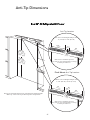
11
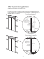
36” All Refrigerator/All Freezer
Anti-Tip Dimensions

24”
(61.0 cm)
1”
(2.54 cm)
Between
Units
82–3/4”
(210.2 cm)
min.
to
84–1/16”
(213.5 cm)
max.
20–3/4”
(52.7 cm)
22–3/16”
(56.4 cm)
75–15/16”
(192 .9 cm
)
3–19/32”
(9.1 cm)
29”
(73.7 cm)
29”
(73.7 cm)
30”30”
(76.2 cm)(76.2 cm)
30”
(76.2 cm)
30”30”
(76.2 cm)(76.2 cm)
30”
(76.2 cm)
26”
(66.0 cm)
9–5/32”
(23.3 cm)
12
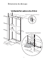
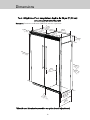
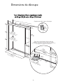
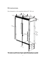
Dual 30” All Refrigerator/All Freezer*
Dimensions
*Shown with optional one-piece grille kit

24”
(61.0 cm)
1”
(2.54 cm)
Between Units
82–3/4”
(210.2 cm)
min.
to
84–1/16”
(213.5 cm)
max.
20–3/4”
(52.7 cm)
22–3/16”
(56.4 cm)
75–15/16”
(192 .9 cm
)
3–19/32”
(9.1 cm)
30”
30”
(76.2 cm)
(76.2 cm)
26”
(66.0 cm)
9–5/32”
(23.3 cm)
35”
(88.9 cm)
29”
(73.6 cm)
36”
(91.5 cm)
30”
(76.2 cm)
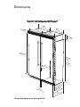
13
Dual 30” & 36” All Refrigerator/All Freezer*
Dimensions
*Shown with optional one-piece grille kit

24”
(61.0 cm)
1”
(2.54 cm)
Between Units
82–3/4”
(210.2 cm)
min.
to
84–1/16”
(213.5 cm)
max.
20–3/4”
(52.7 cm)
22–3/16”
(56.4 cm)
75–15/16”
(192 .9 cm
)
3–19/32”
(9.1 cm)
30”
30”
(76.2 cm)
(76.2 cm)
30”
30”
(76.2 cm)
(76.2 cm)
26”
(66.0 cm)
9–5/32”
(23.3 cm)
35”
(88.9 cm)
35”
(88.9 cm)
36”
(91.5 cm)
36”
(91.5 cm)
14
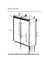
Dual 36” All Refrigerator/All Freezer*
Dimensions
*Shown with optional one-piece grille kit

15
Dual All Refrigerator/All Freezer*
Description (2) 30” Units (1) 36” & (1) 30” Unit (2) 36” Units
Overall width 60” (152.4 cm) 66” (167.6 cm) 72” (182.9 cm)
Overall height from bottom 82-3/4” (210.2 cm) min. to 84-1/16” (213.5 cm) max.
Overall depth from rear To front edge of side trim: 22-3/16” (56.4 cm)
To front of top grille: 24” (61.0 cm)
To front of handle endcap: 26” (66.0 cm)
Cutout width 59-5/8” (151.4 cm) 65-5/8” (166.7 cm) 71-5/8” (181.9 cm)
Cutout height 82-7/8” (210.5 cm) min. to 84-1/16” (213.5 cm) max.
Cutout depth 24” (61.0 cm) min.
Electrical requirements (2) 115 volt, 60 Hz, 15 amp dedicated circuit; 3-wire cord with
grounded 3-prong plug attached to product
Maximum amp usage 30” Freezer 9.1 amps per unit 30” Refrigerator 5.7 amps per unit
36” Freezer 9.5 amps per unit 36” Refrigerator 6.5 amps per unit
Inlet water requirements 1/4” copper tubing inlet waterline; minimum 20 psi;
(All Freezer only) maximum 120 psi
Overall interior dimensions
30” Freezer
15.9 cu. ft. (450 liters)
30” Refrigerator 17.8 cu. ft. (504 liters)
36” Freezer 19.2 cu. ft. (544 liters)
36” Refrigerator 22.0 cu. ft. (623 liters)
Approximate shipping weight 30”- Freezer 550 lbs. (247.5 kg) each; Refrigerator 525 lbs. (236.3 kg) each
36”- Freezer 605 lbs. (272.3 kg) each; Refrigerator 590 lbs. (265.5 kg) each
*For installation of two units side-by-side, a separate grille kit accessory must be purchased.
Specifications

24”
(61.0 cm)
1”
(2.54 cm)
Between
Units
82–3/4”
(210.2 cm)
min.
to
84–1/16”
(213.5 cm)
max.
20–3/4”
(52.7 cm)
23–3/8”
(59.4 cm)
75–15/16”
(192 .9 cm
)
3–19/32”
(9.1 cm)
29”
(73.7 cm)
29”
(73.7 cm)
26”
(66.0 cm)
9–5/32”
(23.3 cm)
30”
(76.2 cm)
30”
(76.2 cm)
16
Dual 30” All Refrigerator/All Freezer with Flush Mount Trim*
Dimensions
*Shown with optional one-piece grille kit
Note: Flush Mount Trim Kit (PBIRFTK) purchased separately

17
24”
(61.0 cm)
1”
(2.54 cm)
Between Units
82–3/4”
(210.2 cm)
min.
to
84–1/16”
(213.5 cm)
max.
20–3/4”
(52.7 cm)
23–3/8”
(59.4 cm)
75–15/16”
(192 .9 cm
)
3–19/32”
(9.1 cm)
30”
30”
(76.2 cm)
(76.2 cm)
26”
(66.0 cm)
9–5/32”
(23.3 cm)
35”
(88.9 cm)
29”
(73.6 cm)
36”
(91.5 cm)
30”
(76.2 cm)
Dual 30” & 36” All Refrigerator/All Freezer with Flush Mount Trim*
Dimensions
*Shown with optional one-piece grille kit
Note: Flush Mount Trim Kit (PBIRFTK) purchased separately

24”
(61.0 cm)
1”
(2.54 cm)
Between
Units
82–3/4”
(210.2 cm)
min.
to
84–1/16”
(213.5 cm)
max.
20–3/4”
(52.7 cm)
23–3/8”
(59.4 cm)
75–15/16”
(192 .9 cm
)
3–19/32”
(9.1 cm)
35”
(88.9 cm)
35”
(88.9 cm)
26”
(66.0 cm)
9–5/32”
(23.3 cm)
36”
(91.5 cm)
36”
(91.5 cm)
18
Dual 36” All Refrigerator/All Freezer with Flush Mount Trim*
Dimensions
Note: Flush Mount Trim Kit (PBIRFTK) purchased separately
*Shown with optional one-piece grille kit (purchased separately)

19
Dual All Refrigerator/All Freezer w/Flush Mount Trim*
Description (2) 30” Units (1) 36” & (1) 30” Unit (2) 36” Units
Overall width 60” (152.4 cm) 66” (167.6 cm) 72” (182.9 cm)
Overall height from bottom 82-3/4” (210.2 cm) min. to 84-1/16” (213.5 cm) max.
Overall depth from rear To front edge of side trim: 23-3/8” (59.4 cm)
To front of top grille: 24” (61.0 cm)
To front of handle endcap: 26” (66.0 cm)
Cutout width 60” (152.4 cm) 66” (167.6 cm) 72” (182.9 cm)
Cutout height 82-7/8” (210.5 cm) min. to 84-1/16” (213.5 cm) max.
Cutout depth 24” (61.0 cm) min.
Electrical requirements (2) 115 volt, 60 Hz, 15 amp dedicated circuit; 3-wire cord with
grounded 3-prong plug attached to product
Maximum amp usage 30” Freezer 9.1 amps per unit 30” Refrigerator 5.7 amps per unit
36” Freezer 9.5 amps per unit 36” Refrigerator 6.5 amps per unit
Inlet water requirements 1/4” copper tubing inlet waterline; minimum 20 psi;
(All Freezer only) maximum 120 psi
Overall interior dimensions
30” Freezer
15.9 cu. ft. (450 liters)
30” Refrigerator 17.8 cu. ft. (504 liters)
36” Freezer 19.2 cu. ft. (544 liters)
36” Refrigerator 22.0 cu. ft. (623 liters)
Approximate shipping weight 30”- Freezer 550 lbs. (247.5 kg) each; Refrigerator 525 lbs. (236.3 kg) each
36”- Freezer 605 lbs. (272.3 kg) each; Refrigerator 590 lbs. (265.5 kg) each
*For installation of two units side-by-side, a separate grille kit accessory must be purchased.
Specifications

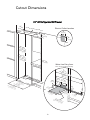
9”
(22.9 cm)
73–3/8”
(186.4 cm)
82–7/8”
(210.5 cm) min.
anti-tip board &
opening height
84–1/16”
(213.5 cm) max.
anti-tip board &
opening height
59–5/8”
(1
51.4 cm)
60”
(1
52.4 cm)
Flush Mount only
24”
(61.0 cm)
Electric Outlet Location
Water Line Entry Area
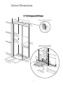
Note: Cutout opening shown with All Freezer model on left.
Reverse water line entry if All Freezer model is on right.
59–5/8”
(151.4 cm)
60”
(152.4 cm)
Flush Mount only
6–3/4”
(17.1 cm)
7–5/8”
(19.4 cm)
3”
(7.6 cm)
5
/8”
(1.5 cm)
5
/8”
(1.5 cm)
10–1/2”
(26.7 cm)
5/8”
(1.5 cm)
10–3/4”
(27.3 cm)
3–5/
8
”
(9.2 cm
)
Optional floor
water li
n
e entry
1”
(2.5 cm
)
See Anti-Tip board installation
6”
(15.2 cm)
9”
(22.9 cm)
20
Dual 30” All Refrigerator/All Freezer
Cutout Dimensions
La page est en cours de chargement...
La page est en cours de chargement...
La page est en cours de chargement...
La page est en cours de chargement...
La page est en cours de chargement...
La page est en cours de chargement...
La page est en cours de chargement...
La page est en cours de chargement...
La page est en cours de chargement...
La page est en cours de chargement...
La page est en cours de chargement...
La page est en cours de chargement...
La page est en cours de chargement...
La page est en cours de chargement...
La page est en cours de chargement...
La page est en cours de chargement...
La page est en cours de chargement...
La page est en cours de chargement...
La page est en cours de chargement...
La page est en cours de chargement...
La page est en cours de chargement...
La page est en cours de chargement...
La page est en cours de chargement...
La page est en cours de chargement...
La page est en cours de chargement...
La page est en cours de chargement...
La page est en cours de chargement...
La page est en cours de chargement...
La page est en cours de chargement...
La page est en cours de chargement...
La page est en cours de chargement...
La page est en cours de chargement...
La page est en cours de chargement...
La page est en cours de chargement...
La page est en cours de chargement...
La page est en cours de chargement...
La page est en cours de chargement...
La page est en cours de chargement...
La page est en cours de chargement...
La page est en cours de chargement...
La page est en cours de chargement...
La page est en cours de chargement...
La page est en cours de chargement...
La page est en cours de chargement...
La page est en cours de chargement...
La page est en cours de chargement...
La page est en cours de chargement...
La page est en cours de chargement...
La page est en cours de chargement...
La page est en cours de chargement...
La page est en cours de chargement...
La page est en cours de chargement...
La page est en cours de chargement...
La page est en cours de chargement...
La page est en cours de chargement...
La page est en cours de chargement...
La page est en cours de chargement...
La page est en cours de chargement...
La page est en cours de chargement...
La page est en cours de chargement...
La page est en cours de chargement...
La page est en cours de chargement...
La page est en cours de chargement...
La page est en cours de chargement...
La page est en cours de chargement...
La page est en cours de chargement...
La page est en cours de chargement...
La page est en cours de chargement...
La page est en cours de chargement...
La page est en cours de chargement...
La page est en cours de chargement...
La page est en cours de chargement...
La page est en cours de chargement...
La page est en cours de chargement...
La page est en cours de chargement...
La page est en cours de chargement...
La page est en cours de chargement...
La page est en cours de chargement...
La page est en cours de chargement...
La page est en cours de chargement...
La page est en cours de chargement...
La page est en cours de chargement...
La page est en cours de chargement...
La page est en cours de chargement...
La page est en cours de chargement...
La page est en cours de chargement...
La page est en cours de chargement...
La page est en cours de chargement...
La page est en cours de chargement...
La page est en cours de chargement...
La page est en cours de chargement...
La page est en cours de chargement...
La page est en cours de chargement...
La page est en cours de chargement...
La page est en cours de chargement...
La page est en cours de chargement...
La page est en cours de chargement...
La page est en cours de chargement...
La page est en cours de chargement...
La page est en cours de chargement...
La page est en cours de chargement...
La page est en cours de chargement...
La page est en cours de chargement...
La page est en cours de chargement...
La page est en cours de chargement...
La page est en cours de chargement...
La page est en cours de chargement...
La page est en cours de chargement...
La page est en cours de chargement...
La page est en cours de chargement...
La page est en cours de chargement...
La page est en cours de chargement...
-
 1
1
-
 2
2
-
 3
3
-
 4
4
-
 5
5
-
 6
6
-
 7
7
-
 8
8
-
 9
9
-
 10
10
-
 11
11
-
 12
12
-
 13
13
-
 14
14
-
 15
15
-
 16
16
-
 17
17
-
 18
18
-
 19
19
-
 20
20
-
 21
21
-
 22
22
-
 23
23
-
 24
24
-
 25
25
-
 26
26
-
 27
27
-
 28
28
-
 29
29
-
 30
30
-
 31
31
-
 32
32
-
 33
33
-
 34
34
-
 35
35
-
 36
36
-
 37
37
-
 38
38
-
 39
39
-
 40
40
-
 41
41
-
 42
42
-
 43
43
-
 44
44
-
 45
45
-
 46
46
-
 47
47
-
 48
48
-
 49
49
-
 50
50
-
 51
51
-
 52
52
-
 53
53
-
 54
54
-
 55
55
-
 56
56
-
 57
57
-
 58
58
-
 59
59
-
 60
60
-
 61
61
-
 62
62
-
 63
63
-
 64
64
-
 65
65
-
 66
66
-
 67
67
-
 68
68
-
 69
69
-
 70
70
-
 71
71
-
 72
72
-
 73
73
-
 74
74
-
 75
75
-
 76
76
-
 77
77
-
 78
78
-
 79
79
-
 80
80
-
 81
81
-
 82
82
-
 83
83
-
 84
84
-
 85
85
-
 86
86
-
 87
87
-
 88
88
-
 89
89
-
 90
90
-
 91
91
-
 92
92
-
 93
93
-
 94
94
-
 95
95
-
 96
96
-
 97
97
-
 98
98
-
 99
99
-
 100
100
-
 101
101
-
 102
102
-
 103
103
-
 104
104
-
 105
105
-
 106
106
-
 107
107
-
 108
108
-
 109
109
-
 110
110
-
 111
111
-
 112
112
-
 113
113
-
 114
114
-
 115
115
-
 116
116
-
 117
117
-
 118
118
-
 119
119
-
 120
120
-
 121
121
-
 122
122
-
 123
123
-
 124
124
-
 125
125
-
 126
126
-
 127
127
-
 128
128
-
 129
129
-
 130
130
-
 131
131
-
 132
132


Marvel MP30RA2LP Guide d'installation
- Catégorie
- Frigos
- Taper
- Guide d'installation
dans d''autres langues
- English: Marvel MP30RA2LP Installation guide
- español: Marvel MP30RA2LP Guía de instalación