Asco Series 165 166 Switch Type Guide d'installation
- Taper
- Guide d'installation

3834912 3834912
2 3
GB
GENERAL
These Installation and Maintenance Instructions are intended for switch type 8074/1-1 with fl ameproof enclosure. Malfunctions, damage
or injury may occur if these instructions are not followed.
All assembly, operation, use, and maintenance must be performed by qualifi ed, authorised personnel.
Essential Health and Safety Requirements:
Flameproof switch type 8074/1-1 is designed in accordance with
Annex II of the European Directive 94/9/EC.
When using an accessory, please observe the specifi c instructions
provided with the accessory to assure the conformity of the assembly
with the ATEX directive.
Caution: The zone classifi cation (ATEX 1999/92/EC) is mainly de-
fi ned by the indications on the label on the valve’s yoke. Safety
code according to ATEX Directive 94/9/EC:II 2GD c T6 T85°C.
When assembling this product to a switch to ATEX 94/9/EC,
take the least favourable category, operating pressures and
temperature into account. Compliance with the Essential Health
and Safety Requirements has been assured by compliance with
European Standards EN 13463-1 and EN 13463-5.
MAINTENANCE
For replacement switch, kits are available, contact us.
The installer is required to proceed in accordance with European
Directive 1999/92/EC and associated standards.
!
Prior to any maintenance work or putting into operation, cut off
the electrical power to prevent the risk of personal injury or damage
to equipment.
!
DO NOT OPEN THE EEx de SWITCH WHILE ENERGISED.
If problems arise during maintenance or in case of doubt, please
contact ASCO or one of its authorised representatives.
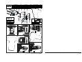
Assembly and reassembly of the switch:
This operation must be carried out by suitably qualifi ed personnel.
• Pre-mount the two pins no. 11 onto the yoke of the AD valve (fi g.
1).
• Assemble the bracket no. 7 with the washers no. 10 and the nuts
no. 9 without tightening it onto the yoke (fi g. 2).
• Mount the adapter plate no. 5 with its guiding pin no. 6 and the
threaded bar no. 8 onto the bracket no. 7 with the screws no. 4
without tightening it (fi g. 3).
• Mount the limit switch no. 3 onto the adapter plate no. 5 with the
washers no. 2 and the screws no. 1 and tighten to the specifi ed
t
orque (fi g. 4).
• Adjust the vertical position of the bracket to detect the top
and bottom end-of-travel, then tighten to the specifi ed torque
(fi g. 5).
• Adjust the position of the adapter plate no. 5 to correctly position
the switch, then tighten to the specifi ed torque (fi g. 6).
FR
GENERALITES
Cette fi che d’instructions d’installation et d’entretien porte sur le boîtier à contact, enveloppe antidéfl agrante, type 8074/1-1. Le non respect
des points mentionnés ci-dessous peut être à l'origine de dysfonctionnements, de dommages ou de blessures.
Les opérations de montage, mise en service, utilisation et maintenance doivent être réalisées par un personnel qualifi é et autorisé.
Exigences essentielles en ce qui concerne la sécurité et la santé
:
Le boîtier à contacts type 8074/1-1 est conçu selon l’Annexe II de
la Directive Européenne 94/9/CE.
En cas d’utilisations d’accessoire, se référer à la notice spécifi que
de l’accessoire pour assurer la conformité de l’ensemble à la
directive ATEX.
Attention : Le placement en zones (ATEX 1999/92/CE) est défi ni
prioritairement par le marquage indiqué sur l'étiquette placée sur
l'arcade de la vanne. Mode de protection, selon ATEX 94/9/CE :
II 2GD c T6 T85°C. Prendre en compte la catégorie, les pres-
sions de fonctionnement et la température la moins favorable
lors d'un assemblage avec le boîtier à contacts ATEX 94/9/CE.
Le respect des exigences essentielles en ce qui concerne la
sécurité et la santé est assuré par la conformité aux normes
européennes EN 13463-1 et EN 13463-5.
ENTRETIEN
Pour le remplacement des contacts, des kits de rechange sont
disponibles, nous consulter.
Lors de l’installation, l’installateur est tenu de suivre les recomman-
dations de la directive 1999/92/CE et normes associées.
!
Avant toute opération d’entretien ou de remise en marche, cou-
per l’alimentation électrique, pour prévenir tout risque d’accident
corporel ou matériel.
!
NE JAMAIS OUVRIR LE BOITIER EEx de SOUS TENSION.
En cas de problème lors du montage/entretien, ou en cas de doute,
contacter le constructeur ou ses représentants offi ciels.
Démontage et remontage des contacts dans le boîtier :
Cette opération doit-être effectuée par un personnel qualifi é.
•
Pré-monter les deux goujons rep.11 sur l'arcade de la vanne AD (fi g.1)
• Assembler l'équerre rep.7 a l'aide des rondelles et écrous rep.10
et 9 sans la serrer sur l'arcade (fi g.2)
• Monter la platine d'adaptation rep.5 avec son pion de guidage
rep.6 sur l'équerre rep.7 à l'aide des vis rep.4 et de la barrette
taraudée rep.8 sans la serrer (fi g.3)
•
Monter le contact de fi n de course rep.3 sur la platine rep.5 avec les
rondelles et les vis rep. 2 et 1, serrer au couple indiqué (fi g.4)
• Ajuster la position en hauteur de l'équerre pour détection fi n de
course haut ou bas puis, serrer au couple indiqué (fi g.5)
• Ajuster la position de la platine rep.5 pour positionner le contact
puis, serrer au couple indiqué (fi g.6)
INSTALLATION AND MAINTENANCE INSTRUCTIONS
Switch type 8074/1-1 with fl ameproof enclosure
INSTRUCTIONS DE MISE EN SERVICE ET D'ENTRETIEN
Boîtier à contact, enveloppe antidéfl agrante, type 8074/1-1
Series
GB
Séries
FR
DE
AD
ATEX
3834912 - R1 (ECN 202556)
ASCO reserves the right to alter the availability, design and specifi cations without notice.
DE
ALLGEMEINES
Diese Inbetriebnahme- und Wartungsanleitung betrifft die Endschalter des Typs 8074/1-1 mit druckfester Kapselung.
Die Nichtbeachtung der nachstehenden Hinweise kann zu Fehlfunktionen, Beschädigungen oder Verletzungen führen.
Die Montage und Inbetriebnahme sowie der Einsatz und die Wartung dürfen nur von entsprechend qualifi ziertem und befugtem Personal
durchgeführt werden.
Wesentliche Anforderungen an Gesundheit und Sicherheit:
Endschalter des Typs 8074/1-1 mit druckfester Kapselung sind
gemäß Anhang II der EU-Richtlinie 94/9/EG konstruiert.
Bei der Verwendung von Zubehörteilen sind die speziellen
Anweisungen für das Zubehörteil heranzuziehen, um die
Konformität der Einheit mit der ATEX-Richtlinie zu gewährleisten.
Wichtiger Hinweis: Der Einsatz in den Zonen (ATEX 1999/92/EG)
richtet sich in erster Linie nach den Angaben auf dem Etikett
an der Laterne des Ventils. Schutzart nach ATEX 94/9/EG:
II 2GD c Ta 60°C T85°C (T6). Beim Zusammenbau mit einem
Endschalter nach ATEX 94/9/EG ist die ungünstigste Kategorie
und Temperatur sowie die ungünstigsten Betriebsdrücke anzu-
nehmen. Die Einhaltung der grundlegenden Gesundheits- und
Sicherheitsanforderungen wird durch die Übereinstimmung
mit den Europäischen Normen EN 13463-1 und EN 13463-5
gewährleistet.
WARTUNG
Für den Austausch der Kontakte sind Ersatzteilpackungen auf
Anfrage erhältlich.
Bei der Installation ist der Installateur verpfl ichtet, die Vorschriften
der EU-Richtlinie 1999/2-2 einschließlich der zugehörigen Normen
einzuhalten.
!
Um Personen- und Sachschäden zu vermeiden, muss vor der
Wartung oder Inbetriebnahme die Spannungsversorgung unterbro-
chen werden.
!
DER NACH EEx de EXGESCHÜTZTE SCHALTER IST NUR IN
SPANNUNGSLOSEM ZUSTAND ZU ÖFFNEN
Treten Schwierigkeiten beim Einbau oder bei der Wartung oder
sonstige Unklarheiten auf, ist mit ASCO oder deren zugelassenen
Vertretern Rücksprache zu halten.
Diese Arbeiten sind von entsprechend qualifi ziertem Personal
durchzuführen.
• Die beiden Stifte Nr. 11 auf der Laterne des Ventils AD (Abb. 1)
vormontieren.
• Den Befestigungswinkel Nr. 7 mit den U-Scheiben Nr. 10 und
den Muttern Nr. 9 an der Laterne montieren ohne diesen
festzuziehen (Abb. 2).
• Die mit dem Führungsstift Nr. 6 versehene Adapterplatte Nr. 5
mit den Schrauben Nr. 4 und der Gewindeleiste Nr. 8 auf den
Befestigungswinkel Nr. 7 montieren, ohne diese fest anzuziehen
(Abb. 3).
• Den Endschalter Nr. 3 auf der Adapterplatte Nr. 5 mit den U-
Scheiben Nr. 2 und den Schrauben Nr. 1 montieren und mit dem
angegebenen Drehmoment festziehen (Abb. 4).
• Die vertikale Position des Befestigungswinkels zur Signalisierung
des oberen und unteren Hubendes einstellen und mit dem
angegebenen Drehmoment festziehen (Abb. 5).
• Die Position der Adapterplatte Nr. 5 für die Kontaktgabe des
Schalters einstellen und anschließend mit dem angegebenen
Drehmoment festziehen (Abb. 6).
ES
INFORMACIÓN GENERAL
Hoja de instalación y mantenimiento provista con la caja de contacto, cubierta antidefl agrante, tipo
8074/1-1
. El no respeto de los puntos mencionados
a continuación puede ser el origen de disfuncionamientos, daños o heridas.
Las operaciones de montaje, puesta en marcha, utilización y mantenimiento deben ser realizadas por personal cualifi cado y autorizado.
Exigencias esenciales en lo relativo a seguridad y salud:
La caja de contactos tipo 8074/1-1 está diseñada según el
Anexo II de la Directiva Europea 94/9/CE.
En el caso de utilización de accesorios, remitirse a la página
específi ca del accesorio para asegurar la conformidad del conjunto
a la directiva ATEX.
Atención : La colocación en zonas (ATEX 1999/92/CE), se
defi ne prioritariamente por el marcaje indicado en la etique-
ta colocada en la arcada de la válvula. Modo de protección,
según ATEX 94/9/CE : II 2GD c T6 T85°C. Tenga en cuenta la
categoría, las presiones de funcionamiento y la temperatura
menos favorable durante un montaje con la caja de contactos
ATEX 94/9/CE. El respeto de las exigencias esenciales en lo
relativo a seguridad y salud está asegurado por la conformidad
a las normas europeas EN 13463-1 y EN 13463-5.
MANTENIMIENTO
Para la sustitución de los contactos, hay disponibles kits de re-
cambio, consultar ASCO.
Seguir imperativamente durante la fase de mantenimiento las re-
comendaciones de la directiva 1999/92/CE y normas asociadas.
!
Antes de cualquier operación de mantenimiento o puesta en
marcha, cortar la alimentación eléctrica, para prevenir todo riesgo
de accidente corporal o material.
!
NO ABRIR JAMÁS LA TAPA EEx de BAJO TENSIÓN
En caso de problemas durante el montaje/mantenimiento, o en caso
de duda, contacte con el fabricante o sus representantes ofi ciales.
Desmontaje y montaje de la caja :
Esta operación debe ser realizada por personal cualifi cado.
•
Pre-montar los dos pasadores ref.11 en la arcada de la válvula AD (fi g.1)
• Montar la escuadra ref.7 con la ayuda de las arandelas y tuercas
ref.10 y 9 sin apretarla en la arcada (fi g.2)
• Montar la pletina de adaptación ref.5 con su guía ref.6 en la
escuadra ref.7 con la ayuda de los tornillos ref.4 y de la barra
perforada ref.8 sin apretarla (fi g.3)
•
Montar el contacto de fi n de carrera ref.3 en la pletina ref.5 con las
arandelas y los tornillos ref. 2 y 1, apretar al par indicado (fi g.4)
• Ajustar la posición en altura de la escuadra para detección de
fi n de carrera alta o baja, después, apretar al par indicado (fi g.5)
• Ajustar la posición de la pletina ref.5 para posicionar el contacto,
después, apretar al par indicado (fi g.6)
INBETRIEBNAHME - UND WARTUNGSANLEITUNG
Endschalter des Typs 8074/1-1 mit druckfester Kapselung
INSTRUCCIONES DE PUESTA EN MARCHA Y MANTENIMIENTO
Caja de contactos, revestimiento antidefl agrante, tipo 8074/1-1
Baureihe
DE
ES
AD
ATEX

3834912 38349124 5
1
2
4
5
3
9
10
11
8
9
10
11
67
ASCO JOUCOMATIC SA
BP 312 - 92506 RUEIL-MALMAISON Cedex - FRANCE
☎
(33) 147.14.32.00 - Fax (33) 147.08.53.85 - www.asconumatics.eu
DRAWINGS GB DESSINS FR ZEICHNUNGEN DE
DISEGNO ES DIBUJO IT TEKENING NL
TEGNINGER NO RITNINGAR SE PIIRUSTUKSET FI
TEGNINGER DK DESENHOS PT
Ó×ÅÄÉÁ
GR
OSNOVY CZ RYSUNKI PL DRAWINGS HU
F
items N.m
Inch.pounds
A
4
±0,5
35,28
±4,41
B
4
±0,5
35,28
±4,41
C
4
±0,5
35,28
±4,41
1 2
3
5
B
6
C
4
A
DN
15 - 32 88216502
88216501
40-50-65-80 88216503
100-125-150 88216504
-
 1
1
-
 2
2


Asco Series 165 166 Switch Type Guide d'installation
- Taper
- Guide d'installation
dans d''autres langues
Documents connexes
-
Asco Series 298 398 Switch Type 8074/1-1 Le manuel du propriétaire
-
-
-
-