
Table of Contents
Parts and Functions
Interface Display .........................................................................1
Icons ..............................................................................................2
Dip Switch ...................................................................................4
Operation
Mode Key ....................................................................................6
Fan Key ........................................................................................6
Temperature Adjustment Keys .................................................7
Special Function
Special Function Selection ..........................................................8
Installer Settings
Adjust ECO Parameters ...........................................................10
Child Lock ................................................................................10
Lock Settings ............................................................................11
Fahrenheit / Celsius ..................................................................11
Temperature Compensation ...................................................12
Forced Defrost/Cooling/Heating ............................................12
Error Checks .............................................................................13
Mode Restriction ......................................................................14
Mode Combination Settings ....................................................15
Wiring Instruction .................................................................... 15
Wired Controller
Installation and Operation Manual
QACT17A
• Please read this manual before use
• Please keep this manual for future reference.
49-5000061 Rev. 1
GEA 09-18

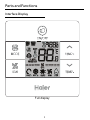
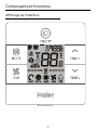
Full display
1
Parts and Functions
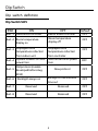
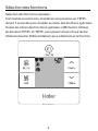
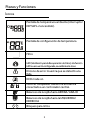
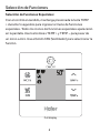
Interface Display

/
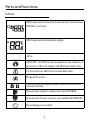
2
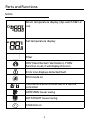
Room temperature display ( dip switch SW1-2
on).
Set temperature display
Filter
HRV (Heat Reclaim Ventilation), if HRV
function is set, it will display this icon
Error icon displays detected fault
ECO mode on
Central/lock when connected to a central
controller
UP/DOWN louver swing
LEFT/RIGHT louver swing
Child lock on
Parts and Functions
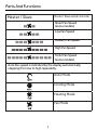
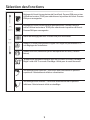
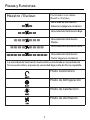
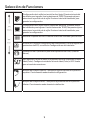
Icons

Master / Slave
Master / Slave wired controller
Quiet Fan Speed
(some models)
Low Fan Speed
Medium Fan Speed
High Fan Speed
Turbo Fan Speed
(some models)
Auto Fan speed is indicated by the display automatically
stepping from low to high repeatedly.
Auto Mode
Cooling Mode
Heating Mode
Fan Mode
3
Parts And Functions

4
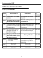
Dip switch denition
Dip Switch SW1
Dip Switch
SW1 ON OFF Default
Sw1-1 Slave wired controller Master wired controller OFF
Sw1-2 Room temperature
display on
Room temperature
display o
OFF
Sw1-3
Displayed room
temperature collected
from indoor unit
Displayed room
temperature collected
from controller
OFF
Sw1-4
System remains o after
power loss
Auto restart after power
loss
OFF
Sw1-5
Old protocol (models
developed before Aug.
2013)
New protocol OFF
Sw1-6 Backlight always on
Backlight 15 second auto
time out
OFF
Sw1-7
Reserved
Reserved OFF
Sw1-8 Reserved Reserved OFF

5
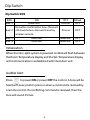
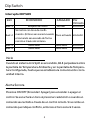
Dip Switch SW2
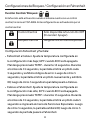
Initialization
When the mini-split system is powered on 88.8 will ash between
the Room Temperature display and the Set Temperature display
until communication is established with the indoor unit.
Press to power ON or power OFF the control. A tone will be
heard with every button press or when a command is received by
a remote control. If a conicting command is received, then the
tone will sound 3 times.
Audible Alert
Dip Switch
SW2 ON OFF Default
Sw2-1 Mode Lock Normal OFF
Sw2-2
No button conrmation tone. (Tone will
still sound when command is sent by
wireless remote.
Tone on OFF
Sw2-3 Reserved Reserved OFF
Sw2-4 Reserved Reserved OFF

Quiet Fan Speed
(some models)
Low Fan Speed
Medium Fan Speed
High Fan Speed
Turbo Fan Speed
(some models)
6
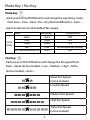
Mode key:
•
Each press of the MODE button will change the operating mode
from Auto – Cool – Heat – Fan – Dry (Dehumidication) – Auto …
• Each mode has its initial default fan speed.
Mode Key / Fan Key
Mode Fan speed Temperature
Auto Auto 76°F
Cool High 76°F
Heat Auto 76°F
Fan Low No temperature display
Dry (Dehumidication) Auto 76°F
Initial
State
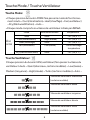
Fan Key:
Each press of the FAN button will change the fan speed from
Auto – Quiet (some models) – Low – Medium – High – Turbo
(some models) – Auto …

7
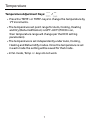
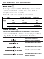
Temperature Adjustment Keys: /
• Press the TEMP+ or TEMP- keys to change the temperature by
1°F increments.
• The temperature set point range for Auto, Cooling, Heating
and Dry (Dehumidication) is 60°F~86°F (If ECO is on,
then temperature range will change per the ECO setting
parameters).
• The temperature is set independently under Auto, Cooling,
Heating and Dehumidify modes. Once the temperature is set
in each mode the setting will be saved for that mode.
• In fan mode, Temp +/- keys do not work.
Temperature

8
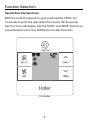
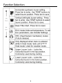
Special Function Selection:
With the control powered on, press and hold the TEMP+ for
5 seconds to enter the special function menu. All the special
function icons will display. Use the TEMP+ and TEMP- buttons to
move between icons. Use FAN button to select function.
Function Selection
Full display

9
Function Selection
50

10
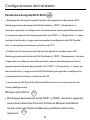
Adjust ECO Parameters:
• Cooling: Power on the unit. Adjust set temperature to 86°F.
Press and hold FAN and TEMP+ for 5 seconds. The minimum
allowable set temperature will be displayed in the top right
corner. Use TEMP+/- to change the parameter, then press FAN
save. The default minimum temperature is 73°F.
• Heating: Power on the unit. Adjust set temperature 60°F.
Press and hold FAN and TEMP- for 5 seconds. The maximum
allowable set temperature will be displayed in the top right
corner. Press TEMP+/- to change the parameter, then press
FAN to save. The default maximum temperature is 79°F.
• Dry (Dehumidication) ECO parameters are the same as Cooling.
Child Lock:
• Press and hold TEMP+ and TEMP- for 5 seconds to activate/
deactivate the Child Lock function. When the Child Lock
function is active, will appear.
Installer Settings

11
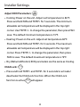
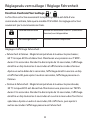
Central/Lock Function: /
Function is active only when system has a central control, such as
the YCZ-A004. This setting is activated only by the central Control.
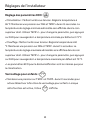
Fahrenheit Setting and Display:
• Fahrenheit to Celsius: Adjust set temperature to lowest
setting; 60°F when ECO is o. Press and hold TEMP- for 15
seconds. During the 15 second count the display will beep
once at 5 seconds and display error codes. Then after another
5 seconds, the display will beep once again and display 00,
after 5 more seconds the display will change to Celsius.
• Celsius to Fahrenheit: Adjust set temperature to highest
setting; 30°C when Eco is o. Press and hold TEMP+ for 15
seconds. During the 15 second count, the display will beep
once at 5 seconds and enter Special Functions menu. Then
after another 5 seconds, the display will show 00, after 5 more
seconds the display will change to Fahrenheit.
Lock Settings / Fahrenheit Setting
Central Control On/O function only available.
Central Lock No functions available.

12
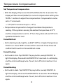
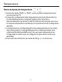
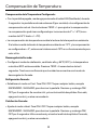
Set Temperature Compensation:
• With the display o, press and hold the FAN button for 5 seconds. The
display will then show 0 (default) or current compensation setting. Use
TEMP+/- buttons to adjust the compensation. Compensation can be
set in 1° increments
+/- 8°F (0.5°C increments up to +/-4°C).
• Temperature compensation changes the ambient temperature
reading. If the system is sensing the ambient temperature at 72°F
and the compensation is set to -2° then the system will use 70°F in its
operation to heat or cool.
Forced Defrost:
• Set to Heating mode, high fan, and 86°F (30°C), or highest temperature
if ECO is on. Press TEMP+ 6 times within 5 seconds. Three tones will
conrm that the unit is in forced defrost mode.
Forced Cooling:
• Set mode to Cool. Tap ON/OFF. Tap any button, except ON/OFF, to
light the display. Press and hold ON/OFF for 5 seconds. LL will display
and the control will beep twice. To exit, turn o control and turn it on
again.
Forced Heating:
• Set mode to Heat. Tap ON/OFF. Tap any button, except ON/OFF, to
light the display. Press and hold ON/OFF for 5 seconds. HH will display
and the control will beep twice. To exit, turn o control and turn it on
again.
Temperature Compensation

13
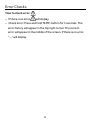
How to check error:
• If there is an error, will display.
• Check error: Press and hold TEMP- button for 5 seconds. The
error history will appear in the top right corner. The current
error will appear in the middle of the screen. If there is no error,
“--” will display.
Error Checks

14
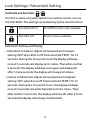
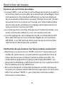
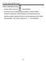
Mode Restriction Function:
• When SW2-1 is on, the system mode lock is on. This will lock
the mode to Heat, Cool, Dry or Fan. No button press can
change mode. All other control functions are available such as
fan speed, set temperature, and on/o.
• Mode can still be changed with a wireless control, another
wired control, or a central control.
• When setting mode lock, have control set to desired mode. Set
dipswitch SW2-1 to ON. Disconnect and reconnect system
power.
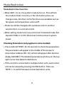
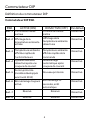
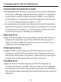
Checking Parameters (only applies to some models):
• Press and hold TEMP+ for 10 seconds to check the parameters.
The parameters will appear in the middle of the screen to
show indoor address (00-15), Letters will appear after decimal
display (AbCdEF). The detailed parameters will show on the top
right corner. See table for denitions.
• If the control is connected to multiple indoor units, each indoor
unit can be viewed by pressing the FAN button. Then use
TEMP+/- to switch between connected indoor units.
Mode Restriction

A B C
A B C
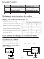
15
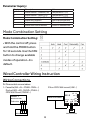
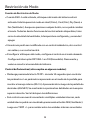
• With the control o, press
and hold the MODE button
for 10 seconds. Use the FAN
button to change available
modes of operation. 4 is
default.
Mode Combination Setting
A: One control on one indoor
Indoor 1
Wired controller
Polar wire
Wired controller
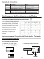
Wired Controller Wiring Instruction
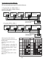
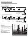
Wiring Connections
1. Cassette (AB…AL…MVAB…MVAL…)
Ducted (AD…AM…MVAD…MVAH…)
MRV Wall Mount (MVAW…)
2 Non-MRV Wall mount (AW...)
Indoor PCB board
Wired controller
LED3/R
SW1
CN4
CN3
CN5
CN1
A B C
A B C
CN2
1 2 3 4
LED1/R LED2/G
WK-B
LED4/G
A B C
Display Description Value
A Indoor sensor - Ambient (Tai) Temperature °F (°C)
b Indoor sensor - Vapor (Tc1) Temperature °F (°C)
C Indoor sensor - Liquid (Tc2 Temperature °F (°C)
d Indoor EEV position Half of actual position
E Indoor unit address Shown in hexadecimal
F Indoor unit central address Shown in hexadecimal
Parameter Inquiry:
Mode Combination Setting:

16
A B C
Indoor 2
Wired controller
A B C
A B C
A B C
Indoor 1
Wired controller
A B C
A B C
Indoor N
Wired controller
Indoor 15
Wired controller
Indoor 16
(master unit)
Wired controller
Control wiring of wired
controller, polar.
Wired controller
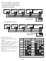
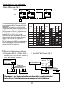
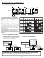
B: One Controller for up to 16 indoor
1. Cassette (AB…AL…MVAB…MVAL…)
Ducted (AD…AM24…MVAD…MVAH…)
MRV Wall Mount (MVAW…)
A B C
Indoor 2
Wired controller
A B C
A B C
A B C
Indoor 1
Wired controller
A B C A B C
Indoor N
Wired controller
Indoor 15
Wired controller
Indoor 16
(master unit)
Wired controller
Control wiring of wired
controller, polar.
Wired controller
2. Ducted (AM36...AM48…)
• Addressing Indoor Units
• Each indoor unit must hvae a unique
address.
• Compact Cassette (AB…) use SW02_1-4
• Large Cassette (AL…) use SW3_5-8
• Slim Duct (AD…) use SW03_1-4
• High Static Duct (AM24…) use SW03_5-8
• High Static Duct (AM36…AM48…) use
SW02_1-4
• All MRV indoor (MV…) use SW01_1-4
Dipswitch position Dipswitch position
Unit # 1 2 3 4 Unit # 1 2 3 4
5 6 7 8 5 6 7 8
0* o o o o 8 on o o o
1 o o o on 9 on o o on
2 o o on o 10 on o on o
3 o o on on 11 on o on on
4 o on o o 12 on on o o
5 o on o on 13 on on o on
6 o on on o 14 on on on o
7 o on on on 15 on on on on
* Unit 0 is connected directly to the control and is master

17
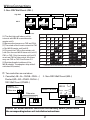
3. Non-MRV Wall Mount (AW...)
Wiring Connections
SW1
Wired controller
Unit 0
... ...
(master unit)
Unit 1
Unit 15
AB C
A B
B
B
C
C
C
A
A
A B C
A B
C
SW1
SW1
High Wall
WK-B
(1) The rst high wall indoor unit to
connect with WK-B is considered as
master unit 0.
(2) Remove the jumpers on CN3 and CN4.
(3) The wired control must connect to CN1
of the WK-B master unit (unit 0).
(4) Connect the CN2 on the master unit
(unit 0) to the next WK-B slave unit (unit 1)
CN1 or CN2. Only the master unit (unit 0)
must use CN1 for the control. All others
may use CN1 or CN2. See Picture 2.2.
(5) Set the dipswitch address of the
WK-B adapter. The adapters ship with all
switches o (master).
C:
Two controllers on one indoor
Notice: For wired controller connection and warranty details, please follow
the corresponding indoor unit installation instructions.
LED3/R LED4/G
A
B
C
A
B
C
Wired controller Wired controller
Polar wire
SW1
CN4
CN3
CN5
CN1
A B C
A B C
CN2
1 2 3 4
LED1/R LED2/G
WK-B
Indoor PCB board
2. Non-MRV Wall Mount (AW…)1. Cassette ( AB…AL…MVAB…MVAL…)
Ducted (AD…AM…MVAD…MVAH…)
MRV Wall Mount (MVAW…)
A B C
A B C
A B C
Indoor 1
Wired controller
Polar wire
Wired controller
Polar wire
Wired controller
Dipswitch position Dipswitch position
Unit # 1 2 3 4 Unit # 1 2 3 4
0* o o o o 8 on o o o
1 o o o on 9 on o o on
2 o o on o 10 on o on o
3 o o on on 11 on o on on
4 o on o o 12 on on o o
5 o on o on 13 on on o on
6 o on on o 14 on on on o
7 o on on on 15 on on on on
* Unit 0 is connected directly to the control and is master

18
C
B
A
red
yellow
white
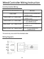
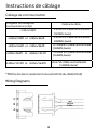
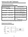
Wired Controller Wiring Instruction
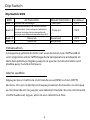
Communication Wiring
*Ground only one end of the shielded cable
Wiring Diagrams
Communication wiring length (m/ft)
Wire Size
< 100m/328ft
0.3mm
2
x3-core shielded wire
(22AWG,3wire)
≥100m/328ft and <200m/656ft
0.5mm
2
x3-core shielded wire
(20AWG,3wire)
≥200m/656ft and <300m/984ft
0.75mm
2
x3-core shielded
wire (18AWG,3wire)
≥300m/984ft and <400m/1312ft
1.25mm
2
x3-core shielded wire
(16AWG,3wire)
≥400m/1312ft and <500m/1640ft
2mm
2
x3-core shielded wire
(14AWG,3wire)

19
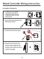
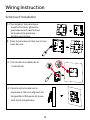
2. Secure the back panel to the
wall using screws.
3. Connect the control wires.
4. Attach the control to the
back panel by aligning the
bottom tabs and then press-
ing the top edge.
Wired Controller Wiring Instruction
Installation Diagrams
1. To take the front panel
and back panel apart,
slide the front panel up
and press down on the
back panel.
La page est en cours de chargement...
La page est en cours de chargement...
La page est en cours de chargement...
La page est en cours de chargement...
La page est en cours de chargement...
La page est en cours de chargement...
La page est en cours de chargement...
La page est en cours de chargement...
La page est en cours de chargement...
La page est en cours de chargement...
La page est en cours de chargement...
La page est en cours de chargement...
La page est en cours de chargement...
La page est en cours de chargement...
La page est en cours de chargement...
La page est en cours de chargement...
La page est en cours de chargement...
La page est en cours de chargement...
La page est en cours de chargement...
La page est en cours de chargement...
La page est en cours de chargement...
La page est en cours de chargement...
La page est en cours de chargement...
La page est en cours de chargement...
La page est en cours de chargement...
La page est en cours de chargement...
La page est en cours de chargement...
La page est en cours de chargement...
La page est en cours de chargement...
La page est en cours de chargement...
La page est en cours de chargement...
La page est en cours de chargement...
La page est en cours de chargement...
La page est en cours de chargement...
La page est en cours de chargement...
La page est en cours de chargement...
La page est en cours de chargement...
La page est en cours de chargement...
La page est en cours de chargement...
La page est en cours de chargement...
La page est en cours de chargement...
La page est en cours de chargement...
La page est en cours de chargement...
-
 1
1
-
 2
2
-
 3
3
-
 4
4
-
 5
5
-
 6
6
-
 7
7
-
 8
8
-
 9
9
-
 10
10
-
 11
11
-
 12
12
-
 13
13
-
 14
14
-
 15
15
-
 16
16
-
 17
17
-
 18
18
-
 19
19
-
 20
20
-
 21
21
-
 22
22
-
 23
23
-
 24
24
-
 25
25
-
 26
26
-
 27
27
-
 28
28
-
 29
29
-
 30
30
-
 31
31
-
 32
32
-
 33
33
-
 34
34
-
 35
35
-
 36
36
-
 37
37
-
 38
38
-
 39
39
-
 40
40
-
 41
41
-
 42
42
-
 43
43
-
 44
44
-
 45
45
-
 46
46
-
 47
47
-
 48
48
-
 49
49
-
 50
50
-
 51
51
-
 52
52
-
 53
53
-
 54
54
-
 55
55
-
 56
56
-
 57
57
-
 58
58
-
 59
59
-
 60
60
-
 61
61
-
 62
62
-
 63
63


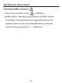
dans d''autres langues
- English: Haier QACT17A Operating instructions
- español: Haier QACT17A Instrucciones de operación
Documents connexes
-
Haier QACT17A Manuel utilisateur
-
Haier 49-5000094-6 Le manuel du propriétaire
-
-
-
-
Haier AD24MS1ERAD Operating Manual And Instructions