Generac 10 kW 0058921 Manuel utilisateur
- Taper
- Manuel utilisateur

INSTALLATION GUIDE
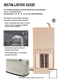
For 100 Amp Automatic Transfer Switch/Load Center Models:
10, 12, 14 and 16 Circuit.
Installed with 8, 10, 12, 13, 14, 16 and 17kW Generators.
This Automatic Transfer Switch with built-in
Load Center includes an Express Install Kit.
• Saves on installation time and cost, in many
cases up to 50% compared to traditional
transfer switch installations.
• Automatically supplies electricity to
selected critical circuits.
• Can be installed prior to, or along with
generator installation.
LISTED
C
US
This manual should remain with the unit.

INSTALLATION GUIDE
INSTALLATION DRAWINGS/WIRING DIAGRAMS .....................................................................................................8
GUÍA DE INSTALACIÓN .........................................................................................................................................15
GUIDE D'INSTALLATION ........................................................................................................................................25
Table of Contents

1
INTRODUCTION
Thank you for purchasing this 100 Amp Automatic Transfer
Switch/Load Center with Express Install Kit. The Express Install
Kit includes:
• 30 foot, five foot, and two foot pre-wired conduits for making all
required wiring runs.
• An outdoor junction box for making connections between out-
door and indoor pre-wired conduits.
• UL listed wire nuts for reconnecting emergency circuits within
the main distribution panel.
The 100 Amp Automatic Transfer Switch/Load Center with Express
Install Kit can be installed along with a 8, 10, 12, 14, 16 or 17kW
Air-cooled Standby Generator, or can be used to pre-wire a home
or small business in advance of generator installation. In either
case, the Express Install Kit saves installation time and cost, since
the majority of labor involved in installing a standby power system
is in wiring the generator, automatic transfer switch and emer-
gency circuit subpanel.
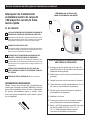
Four commonly used safety symbols accompany the DANGER,
WARNING and CAUTION blocks. The type of information each
indicates follows:
Indicates a hazardous situation or action which, if
not avoided, will result in death or serious injury.
Indicates a hazardous situation or action which,
if not avoided, could result in death or serious
injury.
Indicates a hazardous situation or action which,
if not avoided, could result in minor or moderate
injury.
NOTE:
Notes contain additional information important to a procedure
and will be found within the regular text body of this manual.
These safety warnings cannot eliminate the hazards that they
indicate. Common sense and strict compliance with the special
instructions while performing the action or service are essential to
preventing accidents.
Four commonly used safety symbols accompany the DANGER,
WARNING and CAUTION blocks. The type of information each
indicates is as follows:
This symbol points out important safety
information that, if not followed, could
endanger personal safety and/or property of
others.
This symbol points out potential explosion
hazard.
This symbol points out potential fire hazard.
This symbol points out potential electrical
shock hazard.
SAVE THESE INSTRUCTIONS – The manufacturer sug-
gests that these rules for safe operation be copied and
posted near the unit’s installation site. Safety should be
stressed to all operators and potential operators of this
equipment.
The manufacturer cannot anticipate every possible circumstance
that might involve a hazard. The warnings in this manual, and on
tags and decals affixed to the unit are therefore, not all-inclusive. If
using a procedure, work method or operating technique the manu-
facturer does not specifically recommend, ensure that it is safe for
all personnel. Also make sure the procedure, work method or oper-
ating technique chosen does not render the equipment unsafe.
ELECTRICAL HAZARDS
• Utility power delivers extremely high and dangerous voltages to
the transfer switch as does the standby generator when it is in
operation.
• Do not handle any kind of electrical device while stand-
ing in water, while barefoot, or while hands or feet are wet.
DANGEROUS ELECTRICAL SHOCK MAY RESULT.
• In case of accident caused by electric shock, immediately
shut down the source of electrical power. If this is not pos-
sible, attempt to free the victim from the live conductor. AVOID
DIRECT CONTACT WITH THE VICTIM. Use a non-conducting
implement, such as a rope or board, to free the victim from the
live conductor. If the victim is unconscious, apply first aid and
get immediate medical help.
• Never wear jewelry when working on this equipment. Jewelry
can conduct electricity resulting in electric shock, or may get
caught in moving components causing injury.
PLEASE NOTE:
This installation guide should be used in conjunction with the “Installation and Owner’s Manual” that is fur-
nished with the Air-cooled Standby Generator. Please review both manuals prior to installation of the
generator and transfer switch. This Automatic Transfer Switch/Load Center is not intended for use with the
Liquid-cooled Generator product line. This unit is not compatible with other generator manufacturer’s products.
Residential Transfer Switch Installation Guide

2
100 Amp Automatic Transfer
Switch/Load Center with
Express Install Kit
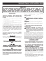
KIT INCLUDES:
THE OUTDOOR CONNECTION BOX WITH FIVE FOOT
PRE-WIRED LIQUID TIGHT CONDUIT
Mounted outside the home or business nearest the
planned generator location. This is for connection to
generator controls and main line circuit breaker.
30 FOOT FLEXIBLE CONDUIT
Pre-wired from the automatic transfer switch with built-
in emergency load center for connection to the outdoor
connection box.
PRE-WIRED AUTOMATIC TRANSFER SWITCH AND
EMERGENCY LOAD CENTER
Installed within one (1) foot of the building’s main distri-
bution panel. This transfer switch provides smooth and
safe transition between utility and generator power.
TWO FOOT PRE-WIRED CONDUIT FOR EASY
CONNECTION TO THE BUILDING’S MAIN
DISTRIBUTION PANEL
UL LISTED WIRE NUTS (not shown)
TOOLS REQUIRED:
Drill, drill bits, hole saw (type and length will be deter-
mined by the materials to be drilled and cut), open-end
wrenches or adjustable wrenches, socket wrenches or
nut drivers, standard and Phillips screwdrivers, sledge
hammer, level, pencil, channel-lock pliers, spade shov-
el, rake and safety goggles.
ITEMS TO BE PURCHASED OR SUPPLIED FOR
COMPLETE INSTALLATION:
70 amp or 40 amp (8kW) double pole circuit breaker
(must be the same type as in the main electrical
distribution panel)
Ground rod with grounding strap (for generator
installation)
Padlock to lock outdoor connection box
Crushed stone or pea gravel (approximately 10-12
cubic feet) (for generator installation)
Black poly-film or other vegetation blocking fabric
(for generator installation)
Silicone caulk
Fasteners (to mount outdoor connection box and
automatic transfer switch)
Battery - 12V automotive type, group 26R, negative
ground, 350 CCA (8kW), 525 CCA (10, 12, 13, 14,
16, 17 and 20kW) minimum capacity (required
as part of generator installation).
A
B
C
D
E
F
G
Designed with installation
cost savings in mind!
A
B
C
D
E
F
Residential Transfer Switch Installation Guide

3
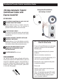
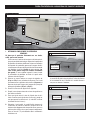
1. PLAN THE LOCATION OF THE GENERATOR.
NOTE:
Do not place the generator directly under a window, eves,
deck or other structure.
Select an area outside of the home or business nearest
the incoming gas service. Determine where the genera-
tor will be placed outside of the building. Arrange for fuel
piping with shut-off valve to be run to this location. Keep
in mind that the manufacturer recommends placement
no closer than 18 inches to any structure. Local codes
may dictate placement farther from a structure. If
facing the unit from the front, the generator's fuel inlet is
located at the rear lower right of the unit.
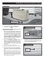
2. Clear an area 62 inches by 50 inches of grass and veg-
etation to a depth of five inches. This includes the dis-
tance the generator should be set away from a structure
(18 inches) and six inches beyond the width and length
of the generator mounting pad (49" L x 25" W).
3. Lay black poly-film to cover the area.
4. Fill the area to ground level with pea gravel or crushed
stone.
5. Drive an eight foot grounding rod into the ground to
grade. Make sure grounding rod and strap are not
exposed above ground level. (NEC code applies to
grounding method.)
6. Determine where the flexible conduit will pass through
the building from inside to outside. When certain there
is clearance on each side of the wall, drill a small pilot
hole through the wall to mark the location. Drill a 1-3/4”
diameter hole through the sheathing and siding with hole
saw.
7. While adhering to all local electrical codes, route the 30
foot conduit along ceiling/floor joists and wall studs to
the location where the conduit will pass through the wall
to the exterior of the building.
1
2
3
5
4
Crushed Stone or Pea Gravel
Site Preparation and Standby Generator Placement
Drill Hole Through House
6
Drill Pass Through Hole
7
1-3/4”
Diameter Hole
1-3/4”
Diameter Hole
Residential Transfer Switch Installation Guide

4
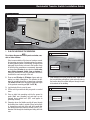
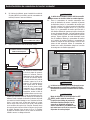
8. From inside the building, feed the end of the 30-foot
conduit (INCLUDED and pre-wired from transfer switch)
through the wall to the outside.
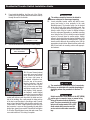
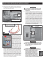
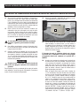
9. Remove the threaded lock nut from the conduit coupling.
10. Lift cover. Remove internal
cover plate screw and internal
cover. Remove the knock out
in the lower right corner of
the external connection box.
From the rear of the connec-
tion box, feed wires, 4-pin and
2-pin plugs into box. Slip the
lock nut over wires and plugs
and tighten securely onto con-
duit coupling. Using appropri-
ate fasteners, mount external
connection box over pre-drilled
hole to fully conceal the hole. Seal around the hole and
conduit with silicone caulk from both the inside and out-
side of the building. Also, caulk around the sides and top
of the box to seal the edges to the siding or wall. Connect
wires to lugs; black to black, white to white, and red to red.
Torque nuts to 20 in/lbs. Snap together the 4-pin and 2-pin
plug connector. Loosen nut from grounding lug and attach
ground wire (green) from conduit. Reinstall nut and tighten
to 45 in/lbs. Reinstall internal cover plate and screw. Close
cover and install lock. This wiring is complete.
The outdoor connection box must be locked to
ensure safety and to discourage tampering.
11. Locate automatic transfer switch with built-in emer-
gency load center in close proximity to the main
distribution panel. The transfer switch can be located
to the left or right of the main distribution panel. One
(1) foot is the suggested distance (see Figure 11). The
transfer switch may be located a different distance
from the main panel depending on available mounting
area. Using the two (2) foot conduit connected straight
across to the main panel is another option. Always
adhere to local electrical codes during installation. Hold
transfer switch against the mounting surface. Level the
transfer switch and mark the mounting holes. Drill the
appropriate size pilot holes. Mount transfer switch with
built-in load center to mounting surface with appropri-
ate fasteners.
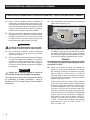
The manufacturer recommends that a licensed elec-
trician or an individual with complete knowledge of
electricity perform the procedures in Sections 12
and 13.
Switch service main circuit breaker to the OFF (OPEN)
position prior to removal of cover or removal of any
wiring of the main electrical distribution
panel. The wires connected to the service
main circuit breaker remain LIVE or HOT.
Avoid contact with these wires and the
service main circuit breaker connection
lugs.
10
Feed Conduit and Wires
8
Silicone
Caulk
The outer diameter of the conduit
connector is 1-11/16”
Threaded Lock Nut
9
The outer diameter of the threaded
end is 15/16 inches.
Mounting Automatic Transfer Switch
11
One (1)
Foot
Suggested
Distance
OFF
Residential Transfer Switch Installation Guide

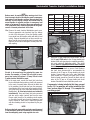
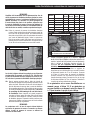
NOTE:
Balance must be maintained when moving circuit loca-
tions from main electrical distribution panel to emergency
load center. Circuit breaker positions alternate buss bars
vertically. Circuits sharing a neutral wire should either be
moved together to adjacent positions in emergency load
center or not moved. If unsure of the proper procedure or
if the installation differs from that described in this guide,
consult a licensed professional at this time.
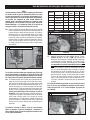
12a. Remove the main electrical distribution panel cover.
Remove appropriate size knockout from the bottom
or side of the main panel. (A two foot flexible conduit
is pre-wired from the transfer switch with built-in load
center). Remove threaded lock nut from conduit cou-
pling. Feed all wires through knockout into main panel.
Slip lock nut over wires and tighten securely onto con-
duit coupling.
NOTE:
Circuits to be moved must be protected by same size
breaker. For example, a 15 amp 120 volt circuit in emer-
gency load center will replace a 15 amp 120 volt circuit
in main electrical distribution panel.
12b. In the main panel, remove the black (hot) wire from
the circuit breaker that protects a circuit to be powered
in the event of a power failure. Wire nut the black wire
to the matching circuit lead wire from the emergency
circuit breaker in the load center in the transfer switch.
(All circuit wires are color coded and labeled for easy
identification). UL listed wire locknuts are included in
installation kit. Trace each black (hot) wire connected
and wire nut the white (neutral) wire from the same
Romex cable (circuit) to the matching circuit number
on the white (neutral) wire from the emergency load
center. Repeat for each circuit. Repeat this process
with the remaining circuits to be powered by the gen-
erator.
NOTE:
Both grounded and ungrounded conductors must be moved
to the emergency panel and connected to the new wiring
from the emergency panel using supplied wire nuts.
Models
10
Circuit
12
Circuit
14
Circuit
16
Circuit
Circuits 50A, 240V - - - 1
40A, 240V - 1 1 1
30A, 240V 1 1 - -
20A, 240V 1 - 1 1
20A, 120V 3365
15A, 120V 3545
13. Install the 70 amp double pole circuit breaker; 10, 13,
14, 16, and 17kW units or the 40 amp double pole
breaker; 8kW units (purchased or supplied separately),
into main electrical distribution panel. This circuit
breaker must be compatible with the main electrical
distribution panel. It may be necessary to reposition
remaining circuit breakers or remove circuit breakers
that have been disconnected to accommodate the
insertion of the 70 amp or 40 amp double pole circuit
breaker. Connect white wire to the main distribution
panel neutral bar. Connect solid green wire to main
electrical panel ground bar. Connect the black and red
wires to the 70 amp or 40 amp double pole circuit
breaker. Reinstall the main distribution panel cover.
If a generator is being installed at this time, proceed
to step 19. If a generator will not be installed at this
time, perform steps 14 through 17 to complete the
pre-wiring project.
Connection of Emergency Circuits
12a
UL approved wire nuts are included with installation kit.
Connection of Emergency Circuits
12b
5
70
70
Install 70 Amp Circuit Breaker
13
Residential Transfer Switch Installation Guide

6
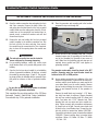
14. Open the outdoor connection box and unplug the 4-pin
and 2-pin connector. Remove the black, white, red,
and green wires that lead from the five foot pre-wired
conduit. Make sure the mating wires from the 30 foot
conduit are on the connection box terminal lugs (or
ground screw), re-install all washers and nuts and
secure them in place.
15. Remove the lock nut holding the five foot pre-wired
conduit coupling to the outdoor connection box. Slip
the lock nut over the wires and plug, then remove
the conduit from the connection box. Use a knockout
plug to close off the opening where the conduit was
removed.
The external connection box must be locked to
ensure safety and to discourage tampering.
16. For pre-existing buildings, switch the service main
circuit breaker back on to provide utility power to the
building.
17. Save the five foot pre-wired conduit for re-installation
at time of generator installation. At that time, re-install
the conduit by reversing steps 14 and 15. The ground-
ing strap will also be installed with the generator. Save
this guide for reference at time of generator installa-
tion.
Be sure the service main circuit breaker is switched
OFF at time of generator installation.
This completes the pre-wiring portion of the 100 Amp
Automatic Transfer Switch/Load Center Installation.
Proceed with step 18 for generator installation.
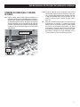
18. Place the generator and mounting pad in the location
prepared in steps one through five.
19. Attach one end of the grounding strap (No. 12 AWG
stranded copper wire) to grounding rod, and the other
end to the grounding lug (located at rear corner of
unit). Make sure the grounding rod and strap are not
exposed above ground level (NEC code applies to
grounding method).
NOTE:
The generator mode switch should be placed in the OFF
position. Generator main line circuit breaker should be
switched to the OFF or OPEN position.
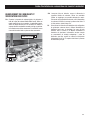
20. Access wiring connections for installation of five foot
harness at the generator. To gain access to wiring con-
nections and the circuit breaker you must remove the
cover plate (black) over the control module. Remove
the two screws retaining the cover plate. Lift the cover
plate up and towards the front of the generator to
remove.
Remove the small black cap (covering 1-1/16” diam-
eter hole) from back of enclosure. Remove threaded
lock nut from conduit coupling (with 90° elbow) and
wires. Feed wires into 1-1/16” diameter hole. Place
threaded lock nut over wires and onto conduit cou-
pling. Tighten securely with screwdriver and hammer
to ensure lock nut is tight. Connect power leads (red
& black) to the circuit breaker lugs. Connect the neu-
tral wire (white) to terminal bar labeled "NEUTRAL".
Connect the ground wire (green) to terminal bar labeled
"GROUND". Connect sensing wires to terminal strips
as follows: Yellow - N1, Yellow - N2, Blue - T1 / White
- 23, Red - 194.
THE AUTOMATIC TRANSFER SWITCH/LOAD CENTER IS NOW INSTALLED!
18
19
Residential Transfer Switch Installation Guide

7
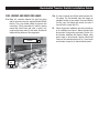
FUEL HOOKUP AND CHECK FOR LEAKS
21a. Make the connection between the rigid fuel piping
and the generator using the supplied threaded flexible
fuel line. Use a pipe sealant suitable for gaseous fuel
connections. Check connections for leaks by opening
manual fuel shut-off valve and swab, or spray, con-
nections with soapy water. If a leak exists, the area will
bubble with the presence of the soapy water.
21b. If a leak is located, shut off fuel and disconnect flex-
ible piping. Dry the threaded ends and reapply an
adequate amount of pipe sealant. Reconnect flexible
fuel line, open fuel supply and recheck for leaks. If
leak still exists, repeat step 21b.
22. Follow all generator installation and setup instructions
in the Installation and Owner’s Manual provided with
the generator. During testing performed in Section 2 of
the generator Installation and Owner’s Manual, utility
power supply to the Automatic Transfer Switch/Load
Center can be controlled using the 40 or 70 amp feeder
circuit breaker located in the main distribution panel.
One (1) Foot Flexible
Fuel Line
21
19
Grounding
Lug
Residential Transfer Switch Installation Guide

8
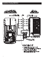
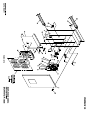
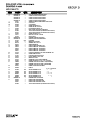
Installation Drawing 0H6393-A

9
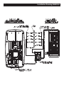
Installation Drawing 0H6393-A

10 10
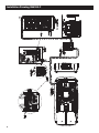
Installation Drawing 0H6392-C

11
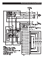
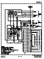
Electrical Schematic Drawing 0H6386-B

12
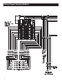
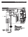
Wiring Diagram Drawing 0H6385-A

13
Wiring Diagram Drawing 0H6385-A

Part No. 0H6391 Revision F (09/26/12) Catalog No. KGATX0316100-1SI Printed in U.S.A.

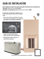
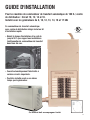
GUÍA DE INSTALACIÓN
Para modelos de centro de carga/interruptor de transferencia automática de
100 amp: de 10, 12, 14 y 16 circuitos.
Instalado con generadores de 8, 10, 12, 13, 14, 16 y 17kW.
Este interruptor de transferencia automática con cen-
tro de carga incorporado incluye un kit de instalación
rápida.
• Ahorra costos y tiempos de instalación, en muchos
casos hasta el 50% comparado con las instalaciones
de interruptores de transferencia tradicionales.
• Suministra electricidad automática-
mente a circuitos críticos seleccionados.
• Puede instalarse antes o junto con la
instalación del generador.
LISTED
C
US
Este manual deberá permanecer con la unidad.

16

17
Guía de instalación del interruptor de transferencia residencial
INTRODUCCIÓN
Gracias por comprar este interruptor de transferencia automática /
centro de carga con kit de instalación rápida. El kit de instalación
rápida incluye:
• Conductos pre-cableados de 30 pies, cinco y dos pies para
todo el cableado requerido.
• Una caja de conexiones de exteriores para hacer conexiones
entre los conductos pre-cableados de exteriores e interiores.
• Tuercas para cable listadas en UL para reconectar circuitos de
emergencia dentro del panel de distribución principal.
El interruptor de transferencia automática/centro de carga de 100
amp con kit de instalación rápida puede instalarse junto con el
generador de respaldo enfriado por aire de 8, 10, 12, 14, 16 o
17kW o se puede usar para pre-cablear un domicilio o pequeña
empresa antes de la instalación del generador. En cualquier caso,
el kit de instalación rápida ahorra tiempo y costo de instalación, ya
que la mayor parte del trabajo involucrado en instalar un sistema
de energía en stand by está en el cableado del generador, el inter-
ruptor de transferencia automática y el subpanel de circuito de
emergencia.
Cuatro símbolos de seguridad usados comúnmente acompañan
los bloques de PELIGRO, ADVERTENCIA y CUIDADO. El tipo de
información que cada uno indica es como sigue:
PELIGRO
Indica una situación peligrosa o acción que, si
no se evita, traerá como resultado la muerte o un
daño serio.
ADVERTENCIA
Indica una situación peligrosa o acción que, si no
se evita, puede traer como resultado la muerte o
un daño serio.
CU
IDAD
O
Indica una situación peligrosa o acción que, si
no se evita, puede traer como resultado un daño
menor o moderado.
NOTA:
Las notas contienen información adicional importante para un
procedimiento y se les encontrará dentro del cuerpo de este
manual.
Estas advertencias de seguridad no pueden eliminar los peligros
que indican. El sentido común y un estricto cumplimiento de las
instrucciones especiales cuando se realiza la acción o servicio
son esenciales para evitar accidentes.
Cuatro símbolos de seguridad usados comúnmente acompañan
los bloques de PELIGRO, ADVERTENCIA y CUIDADO. El tipo de
información que cada uno indica es como sigue:
Este símbolo señala importante información
de seguridad que, si no se sigue, puede
poner en peligro la seguridad personal y/o
las propiedades de otros.
Este símbolo indica un peligro potencial de
explosión.
Este símbolo indica un peligro potencial de
incendio.
Este símbolo indica un peligro potencial de
choque eléctrico.
GUARDE ESTAS INSTRUCCIONES – El fabricante sugiere
que estas reglas para la operación segura se copien y
publiquen cerca del sitio de instalación de la unidad.
Debe insistirse en la seguridad para todos los opera-
dores y potenciales operadores de este equipo.
El fabricante no puede anticipar todas las posibles circunstancias
que puedan involucrar peligros. Las advertencias en este manual y
en las etiquetas y calcomanías fijadas en la unidad son, por tanto,
no completamente inclusivas. Si se usa un procedimiento, método
de trabajo o técnica de operación que el fabricante no recomienda
específicamente, asegúrese de que sea seguro para todo el
personal. Asimismo asegúrese que el procedimiento, método de
trabajo o técnica elegida utilizada no vuelva inseguro al equipo.
PELIGROS ELÉCTRICOS
• El servicio eléctrico doméstico entrega voltajes altos y peli-
grosos al interruptor de transferencia como lo hace el genera-
dor cuando está en operación.
• No manipule ningun tipo de dispositivo eléctrico mientras esté
de pie sobre agua, con los pies descalzos o con las manos o
pies húmedos. PUEDE HABER UNA DESCARGA ELÉCTRICA
COMO RESULTADO.
• En caso de un accidente causado por descarga eléctrica,
apague inmediatamente la fuente de energía eléctrica. Si esto
no es posible, intente liberar a la víctima del conductor vivo.
EVITE EL CONTACTO DIRECTO CON LA VÍCTIMA. Une un
implemento no conductivo, como una soga o una tabla, para
liberar a la víctima del conductor vivo. Si la víctima está incon-
sciente, aplique los primeros auxilios y consiga ayuda médica
inmediatamente.
• Nunca use joyas al trabajar con este equipo. Las joyas pueden
conducir electricidad y traer como resultado una descarga eléc-
trica, o puede quedar atrapada en los componentes móviles.
POR FAVOR NOTAR:
Esta guía de instalación deberá usarse junto con el “Manual del propietario e instalación” que se proporciona con el
generador de respaldo enfriado por aire. Por favor revise ambos manuales antes de la instalación del generador e inter-
ruptor de transferencia. Este interruptor de transferencia automática/centro de carga no está previsto para usarse con la
línea de productos de generador enfriado por líquido. Esta unidad no es compatible con otros productos de fabricantes
de generadores.

18
Guía de instalación del interruptor de transferencia residencial
Interruptor de transferencia
automática/centro de carga de
100 amperios con kit de insta-
lación rápida
EL KIT INCLUYE:
LA CAJA DE CONEXIONES DE EXTERIORES CON CONDUCTO
ESTRECHO DE LÍQUIDO PRE CABLEADO DE CINCO PIES
Montado fuera del domicilio o empresa más cercana a la ubi-
cación del generador. Esto es para la conexión a los controles
del generador e interruptor de circuito de línea principal.
CONDUCTO FLEXIBLE DE 30 PIES
Pre-cableado desde el interruptor de transferencia automática
con centro de carga de emergencia incorporado para conec-
tarse a la caja de conexiones de exteriores.
INTERRUPTOR DE TRANSFERENCIA AUTOMÁTICA PRE-
CABLEADA Y CENTRO DE CARGA DE EMERGENCIA
Instalado dentro de un (01) pie del panel de distribución prin-
cipal del edificio. Este interruptor de transferencia proporciona
una transición suave y segura entre la energía comercial y la
del generador.
CONDUCTO PRE-CABLEADO DE DOS PIES PARA UNA
FÁCIL CONEXIÓN AL PANEL DE DISTRIBUCIÓN PRINCIPAL
DEL EDIFICIO
TUERCAS DE CABLE LISTADAS EN UL (no se muestra)
HERRAMIENTAS REQUERIDAS:
Taladro, brocas, sierra circular (tipo y longitud a deter-
minarse por el material a coratse y taladrarse), llaves de
boca o llaves ajustables, llaves de cubo o desarmador
de tuercas, desarmadores planos y estrella, mazo,
nivel, lápìz, pinzas channel-lock, pala, rastrillo y anteo-
jos de seguridad.
¡Diseñado con el ahorro del
costo de instalación en mente!
ITEMS A ADQUIRIRSE O SUMINISTRARSE PARA
UNA COMPLETA INSTALACIÓN:
Interruptor de circuito de doble polo de 70 amp o 40
amp (8kW) (debe ser del mismo tipo que en el panel de
distribución eléctrica principal)
Varilla de tierra con tira de tierra (para instalación del
generador)
Candado p/cerrar la caja de conexiones de exteriores
Piedra chancada o gravilla (aproximadamente 10 a 12
pies cúbicos) (para instalación del generador)
Poly-film nego u otra tela de bloqueo de vegetación
(para instalación del generador)
Masillado con silicona
Correas (para montar la caja de conexiones de exteri-
ores y el interruptor de transferencia automática)
Batería - de 12V tipo automotor, grupo 26R, tierra nega-
tiva, 350 CCA (8kW), 525 CCA (10, 12, 13, 14,
16, 17 y 20kW) capacidad mínima (requerida
como parte de la instalación del generador).
C
D
E
F
G
A
B
C
D
E
F
A
B
La page est en cours de chargement...
La page est en cours de chargement...
La page est en cours de chargement...
La page est en cours de chargement...
La page est en cours de chargement...
La page est en cours de chargement...
La page est en cours de chargement...
La page est en cours de chargement...
La page est en cours de chargement...
La page est en cours de chargement...
La page est en cours de chargement...
La page est en cours de chargement...
La page est en cours de chargement...
La page est en cours de chargement...
La page est en cours de chargement...
La page est en cours de chargement...
La page est en cours de chargement...
La page est en cours de chargement...
La page est en cours de chargement...
La page est en cours de chargement...
-
 1
1
-
 2
2
-
 3
3
-
 4
4
-
 5
5
-
 6
6
-
 7
7
-
 8
8
-
 9
9
-
 10
10
-
 11
11
-
 12
12
-
 13
13
-
 14
14
-
 15
15
-
 16
16
-
 17
17
-
 18
18
-
 19
19
-
 20
20
-
 21
21
-
 22
22
-
 23
23
-
 24
24
-
 25
25
-
 26
26
-
 27
27
-
 28
28
-
 29
29
-
 30
30
-
 31
31
-
 32
32
-
 33
33
-
 34
34
-
 35
35
-
 36
36
-
 37
37
-
 38
38
-
 39
39
-
 40
40


Generac 10 kW 0058921 Manuel utilisateur
- Taper
- Manuel utilisateur
dans d''autres langues
- English: Generac 10 kW 0058921 User manual
- español: Generac 10 kW 0058921 Manual de usuario