Kichler Lighting 49876BK Manuel utilisateur
- Taper
- Manuel utilisateur

IS-49876-US
We’re here to help 866-558-5706
Hrs: M-F 9am to 5pm EST
1) Find the appropriate threaded holes on mounng
strap[A] that align with hole distance in canopy[E].
Thread mounng screws[D] into threaded holes starng
from outlet box[B] side.
2) Aach mounng strap to outlet box with strap mounng
screws[C]. Mounng strap can be adjusted to suit
posion of xture.
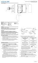
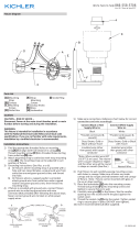
3) Grounding instrucons: (See Illus. a or b).
a) On xtures where mounng strap is provided with a
hole and two raised dimples, wrap ground wire from
outlet box around green ground screw, and thread
into hole.
b) On xtures where a cupped washer is provided,
aach ground wire from outlet box under cupped
washer and green ground screw, then thread into
mounng strap.
If xture is provided with ground wire, connect xture
ground wire to outlet box ground wire with wire
connector (Not provided) aer following the above steps.
Never connect ground wire to black or white power
supply wires.
4) Make wire connecons. Reference chart below for
correct connecons and wire accordingly.
Connect Black or Red
Supply Wire to:
Connect White Supply
Wire to:
Black White
*Parallel cord (round &
smooth)
*Parallel cord (square &
ridged)
Clear, Brown, Gold or
Black without Tracer
Clear, Brown, Gold or Black
with Tracer
Insulated wire (other
than green) with copper
conductor
Insulated wire (other
than green) with silver
conductor
*Note: When parallel wire (SPT
1 & SPT 2) are used. The neutral
wire is square shaped or ridged
and the other wire will be round
in shape or smooth (See illus.)
Neutral Wire
5) Push xture to wall over the protruding screws in the
mounng strap. Be sure not to pinch wires between wall
and canopy of xture.
6) Screw on the two (2) ball knobs[F] to the canopy[E]
Tighten to secure.
7) Insert recommended bulb(s). (Not supplied)
8) Place the glass[J] over the installed bulb and secure into
place using four (4) ball knobs[F] by threading on the
protruding studs.
9) Lower the top[H] onto the frame as shown and secure
into place with the two (2) screws[I].
10) Take the decorave arm[G] and hook into the large
loop and secure to the canopy using the sheet metal
screw[K].
GREEN GROUND
SCREW
CUPPED
WASHER
OUTLET BOX
GROUND
FIXTURE
GROUND
DIMPLES
WIRE CONNECTOR
OUTLET BOX
GROUND
GREEN GROUND
SCREW
FIXTURE
GROUND
a
b
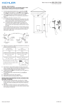
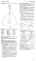
Fixture Diagram
Parts List
Cauons
CAUTION – RISK OF SHOCK –
Disconnect Power at the main circuit breaker panel or main
fusebox before starng and during the installaon.
WARNING:
This xture is intended for installaon in accordance
with the Naonal Electrical Code (NEC) and all local code
specicaons. If you are not familiar with code requirements,
installaon by a cered electrician is recommended.
Installaon Instrucons
[A] Mounting Strap
[B] Outlet Box
[C] Strap Mounting
Screws
[D] Mounting
Screws
[E] Canopy
[F] Ball Knobs
[G] Decorative Arm
[H] Top
[I] Screws
[J] Glass
[K] Sheet Metal
Screw
E
F
A
C
B
D
G
H
I
J
K
F
INSTRUCTIONS FOR MOUNTING FIXTURE OUTDOORS AND/
OR IN WET LOCATIONS.
• Mounng surface should be clean, dry, at and 1/4”
larger than the canopy on all sides. Any gaps between the
mounng surface and canopy exceeding 3/16” should be
corrected as required.
• With silicone caulking compound, caulk completely
around where back of canopy meets the wall surface to
prevent water from seeping into outlet box.

IS-49876-US
Estamos aquí para ayudarle 866-558-5706
Horario: Lunes-Viernes 9am a 5pm EST (hora ocial del este)
2) Fije la correa de montaje a la caja de salida con los
tornillos de jación de la correa[C]. La correa de montaje
se puede ajustar para adaptarse a la posición del
aparato.
3) Instrucciones de conexión a erra solamente para los
Estados Unidos. (Vea la ilustracion a o b).
a) En las lámparas que enen el eje, de montaje con
un agujero y dos hoyuelos realzados, enrollar el
alambre a erra de la caja tomacorriente alrededor
del tornillo verde y pasarlo por el aquiero.
b) En las lámparas con una arandela acopada, jar el
alambre a erra de la caja tomacorriente del ajo de
la arandela acoada y tornillo verde, y paser por el
eje de montaje.
Si la lámpara viene con alambre a erra, conecter el
alambre a erra de la lámpara al alambre a erra de la
caja tomacorriente con un conector de alambres (No
incluido) espués de seguir los pasos anteriores. Nunca
conectar el alambra a erra a los alambres eléctros
negro o blanco.
4) Haga les conexiones de los alambres. La tabla de
referencia de abajo indica las conexiones correctas y los
alambres correspondientes.
Conectar el alambre de
suministro negro o rojo al
Conectar el alambre de
suministro blanco al
Negro Blanco
*Cordon paralelo (redondo
y liso)
*Cordon paralelo (cuadrado
y estriado)
Claro, marrón, amarillio
o negro sin hebra
idencadora
Claro, marrón, amarillio
o negro con hebra
idencadora
Alambre aislado (diferente
del verde) con conductor
de cobre
Alambre aislado (diferente
del verde) con conductor
de plata
*Nota: Cuando se uliza alambre
paralelo (SPT 1 y SPT 2). El alambre
neutro es de forma cuadrada o
estriada y el otro alambre será
de forma redonda o lisa. (Vea la
ilustracíón).
Hilo Neutral
5) Empuje el artefacto a la pared sobre los tornillos que
sobresalen de la abrazadera de montaje. Asegúrese de
no apretar los cables entre la pared y el escudete del
artefacto.
6) Atornille las dos (2) perillas redondas [F] al dosel [E].
Ajústelas para asegurarlas.
7) Inserte la(s) bombilla(s) recomendada(s). (No
suministradas).
8) Coloque el vidrio [J] sobre la bombilla instalada y
asegúrelo en su lugar usando cuatro (4) perillas redondas
[F] enroscándolas en los espárragos que sobresalen.
9) Baje la parte superior [H] sobre el marco como se
muestra y jela en su lugar con los dos (2) tornillos [I].
10) Tome el brazo decoravo [G] y engánchelo en el anillo
grande, y jelo al escudete usando el tornillo para metal
[K].
ARANDELA
CONCAVA
TIERRA DE LA
CAJA DE SALIDA
TORNILLO DE TIERRA,
VERDE
DEPRESIONES
TIERRA
ARTEFACTO
CONECTOR DE ALAMBRE
TIERRA DE LA
CAJA DE SALIDA
TORNILLO DE TIERRA,
VERDE
TIERRA
ARTEFACTO
a
b
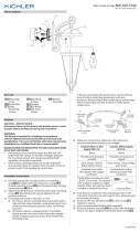
Diagrama de Accesorios
Lista de Partes
[A] Correa de
Montaje
[B] Caja de Salida
[C] Tornillos de
Fijación de la
Correa
[D] Tornillos de
Montaje
[E] Dosel
[F] Perillas
redondas
[G] Brazo
decoravo
[H] Parte superior
[I] Tornillos
[J] Vidrio
[K] Tornillo para
metal
Precauciones
PRECAUCIÓN – RIESGO DE DESCARGA ELÉCTRICA –
Desconecte la electricidad en el panel principal del
interruptor automáco o caja principal de fusibles antes de
comenzar y durante la instalación.
ADVERTENCIA:
Este accesorio está desnado a la instalación de
acuerdo con el Naonal Electrical Code (NEC) y todas las
especicaciones del código local. Si no está familiarizado
con los requisitos del código, la instalación se recomienda
un electricista cercado.
Instrucciones de Instalación
1) Encuentre los oricios roscados adecuados en la correa
de montaje[A] que se alinean con la distancia del agujero
en el dosel[E]. Enrosque los tornillos de montaje[D]
en los oricios roscados desde el lado de la caja de
salida[B].
E
F
A
C
B
D
G
H
I
J
K
F
INSTRUCCIONES PARA EL MONTAJE DEL ARTEFACTO AL
AIRE LIBRE Y/O EN UN LUGAR MOJADO.
• La supercie de montaje debe estar limpia, seca, ser
plana y 1/4” más grande que el esdudete en todos
los bordes. Cualquier espacio libre entre la supercie
de montaje y el escudete que exceda de 3/16” debe
corregirse según se requiera.
• Calafatee totalmente con compuesto de calafatear
de silicona alrededor donde el escudete sienta en la
supercie de la pared para impedir la entrada de agua en
la caja de conexiones.

IS-49876-CB
We’re here to help 866-558-5706
Hrs: M-F 9am to 5pm EST
1) Find the appropriate threaded holes on mounng
strap[A] that align with hole distance in canopy[E].
Thread mounng screws[D] into threaded holes starng
from outlet box[B] side.
2) Aach mounng strap to outlet box with strap mounng
screws[C]. Mounng strap can be adjusted to suit
posion of xture.
3) Grounding instrucons: (See Illus. a or b).
a) On xtures where mounng strap is provided with a
hole and two raised dimples, wrap ground wire from
outlet box around green ground screw, and thread
into hole.
b) On xtures where a cupped washer is provided,
aach ground wire from outlet box under cupped
washer and green ground screw, then thread into
mounng strap.
If xture is provided with ground wire, connect xture
ground wire to outlet box ground wire with wire
connector (Not provided) aer following the above steps.
Never connect ground wire to black or white power
supply wires.
4) Make wire connecons. Reference chart below for
correct connecons and wire accordingly.
Connect Black or Red
Supply Wire to:
Connect White Supply
Wire to:
Black White
*Parallel cord (round &
smooth)
*Parallel cord (square &
ridged)
Clear, Brown, Gold or
Black without Tracer
Clear, Brown, Gold or Black
with Tracer
Insulated wire (other
than green) with copper
conductor
Insulated wire (other
than green) with silver
conductor
*Note: When parallel wire (SPT
1 & SPT 2) are used. The neutral
wire is square shaped or ridged
and the other wire will be round
in shape or smooth (See illus.)
Neutral Wire
5) Push xture to wall over the protruding screws in the
mounng strap. Be sure not to pinch wires between wall
and canopy of xture.
6) Screw on the two (2) ball knobs[F] to the canopy[E]
Tighten to secure.
7) Insert recommended bulb(s). (Not supplied)
8) Place the glass[J] over the installed bulb and secure into
place using four (4) ball knobs[F] by threading on the
protruding studs.
9) Lower the top[H] onto the frame as shown and secure
into place with the two (2) screws[I].
10) Take the decorave arm[G] and hook into the large
loop and secure to the canopy using the sheet metal
screw[K].
GREEN GROUND
SCREW
CUPPED
WASHER
OUTLET BOX
GROUND
FIXTURE
GROUND
DIMPLES
WIRE CONNECTOR
OUTLET BOX
GROUND
GREEN GROUND
SCREW
FIXTURE
GROUND
a
b
Fixture Diagram
Parts List
Cauons
CAUTION – RISK OF SHOCK –
Disconnect Power at the main circuit breaker panel or main
fusebox before starng and during the installaon.
WARNING:
This xture is intended for installaon in accordance
with the Naonal Electrical Code (NEC) and all local code
specicaons. If you are not familiar with code requirements,
installaon by a cered electrician is recommended.
Installaon Instrucons
[A] Mounting Strap
[B] Outlet Box
[C] Strap Mounting
Screws
[D] Mounting
Screws
[E] Canopy
[F] Ball Knobs
[G] Decorative Arm
[H] Top
[I] Screws
[J] Glass
[K] Sheet Metal
Screw
E
F
A
C
B
D
G
H
I
J
K
F
INSTRUCTIONS FOR MOUNTING FIXTURE OUTDOORS AND/
OR IN WET LOCATIONS.
• Mounng surface should be clean, dry, at and 1/4”
larger than the canopy on all sides. Any gaps between the
mounng surface and canopy exceeding 3/16” should be
corrected as required.
• With silicone caulking compound, caulk completely
around where back of canopy meets the wall surface to
prevent water from seeping into outlet box.

IS-49876-CB
Nous sommes là pour vous aider 866-558-5706
Heures : du lundi au vendredi, de 9h à 17h (heure de l’Est)
INSTRUCTIONS:
For Assembling and Installing Fixtures in Canada
Pour L’assemblage et L’installaon Au Canada
1) Trouvez les trous letés appropriés sur la sangle de
montage[A] qui s’alignent avec la distance du trou dans
le couvert[E]. Vis de montage[D] du letage dans les
trous letés à parr du côté sore[B] côté.
2) Fixez la sangle de montage à la boîte de sore avec les
vis de xaon de la sangle[C]. La sangle de montage
peut être réglée en foncon de la posion du luminaire.
3) Connecter les ls. Se reporter au tableau ci-dessous pour
faire les connexions.
Connecter le l noir ou
rouge de la boite
Connecter le l blanc de
la boîte
A Noir A Blanc
*Au cordon parallèle (rond
et lisse)
*Au cordon parallèle (à
angles droits el strié)
Au transparent, doré,
marron, ou noir sans l
disncf
Au transparent, doré,
marron, ou noir avec un l
disncf
Fil isolé (sauf l vert) avec
conducteur en cuivre
Fil isolé (sauf l vert) avec
conducteur en argent
*Remarque: Avec emploi d’un
l paralléle (SPT 1 et SPT 2). Le
l neutre est á angles droits ou
strié et l’autre l doit étre rond
ou lisse (Voir le schéma).
Fil Neutre
4) Poussez le luminaire vers le mur par-dessus les vis
dépassant de la surface dans le support de montage. Ne
pas pincer les ls entre le mur et le cache du luminaire.
5) Vissez les deux (2) boules à bille [F] sur le cache [E].
Serrez pour xer.
6) Installez la ou les ampoules recommandées (non
fournies).
7) Placez le verre [J] sur l’ampoule installée et xez-le à
l’aide de quatre (4) boules à bille [F] en vissant sur les
goujons dépassant de la surface.
8) Abaissez la pare supérieure [H] sur le cadre (voir
illustraon) et xez-la avec les deux (2) vis [I].
9) Prenez le bras décoraf [G], accrochez-le à la grande
boucle et xez-le au cache à l’aide de la vis de feuille
métallique [K].
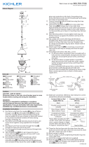
Diagramme d’appareils
ATTENTION – RISQUE DE DÉCHARGES ÉLECTRIQUES -
Couper le courant au niveau du panneau du disjoncteur du
circuit principal ou de la boîte à fusibles principale avant de
procéder à l’installaon.
ATTENTION:
Ce luminaire doit être installé conformément aux codes
d’électricité naonaux (NEC) et sasfaire toutes les
spécicaons des codes locaux. Si vous ne connaissez pas
les exigences de ces codes, il est recommandé de coner
l’installaon à un électricien ceré.
Liste des Pièces
Précauons
[A] Sangle de
Montage
[B] Côté Sortie
[C] Vis de Fixation
de la Sangle
[D] Vis de
Montage
[E] Couvert
[F] Boutons de
Verrouillage
[G] Bras décoraf
[H] Pare
supérieure
[I] Vis
[J] Verre
[K] Vis de feuille
métallique
Instrucons d’installaon
E
F
A
C
B
D
G
H
I
J
K
F
INSTRUCTIONS DE MONTAGE DE LUMINAIRE À
L’EXTÉRIEUR ET/OU DANS DES LIEUX HUMIDES.
• La surface de montage doit être propre, sèche, plate et
de 0,6 cm plus épaisse que le cache sur tous les côtés.
Tout écart entre la surface de montage et le cache
dépassant de 0,5 cm doit être recé selon les besoins.
• À l’aide de matériaux d’étanchéité à la silicone, calfeutrer
bien autour où l’arrière du cache entre en contact avec
le mur pour empêcher l’eau de passer dans la boîte de
raccordement.
-
 1
1
-
 2
2
-
 3
3
-
 4
4


Kichler Lighting 49876BK Manuel utilisateur
- Taper
- Manuel utilisateur
dans d''autres langues
Documents connexes
-
 Kichler Lighting 49286OZ Manuel utilisateur
-
 Kichler Lighting 49872WZC Manuel utilisateur
-
 Kichler Lighting 49233BSL Manuel utilisateur
-
 Kichler Lighting 43011NBR Manuel utilisateur
-
 Kichler Lighting 43034DAG Manuel utilisateur
-
Kichler Lighting 45916NI Manuel utilisateur
-
 Kichler Lighting 49986DBK Manuel utilisateur
-
Kichler Lighting 49866WZC Manuel utilisateur
-
 Kichler Lighting 45696OZ Manuel utilisateur
-
 Kichler Lighting 55013BK Manuel utilisateur


