
DO GUIDE
DM-TX-4KZ-202-C/DM-TX-4KZ-302-C
DigitalMedia 8G+
®
4K60 4:4:4 HDR Transmitters
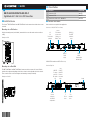
DO Connect the Device
Connect the device as required for the application.
Connections, Left Side (DM-TX-4KZ-302-C Shown)
Connections, Right Side
DO Install the Device
The Crestron
®
DM-TX-4KZ-202-C and DM-TX-4KZ-302-C can be mounted onto a at surface or onto
a rack rail.
Mounting onto a Flat Surface
Using four mounting screws (not included), mount the device onto a at surface such as a wall or a
ceiling.
Mounting onto a Wall
Mounting onto a Rack Rail
The DM-TX-4KZ-202-C and DM-TX-4KZ-302-C mount onto the front or rear rail of a rack. Position
either the left or right mounting ange of the device so that the holes align with the holes in the rack.
Then, secure the device to the rack using two rack mounting screws (not included).
Mounting onto a Rack Rail
DO Check the Box
QTY PRODUCT PART NUM.
1 Connector, 2-Pin 20 03574
1 Connector, 5-Pin 2003577
1 Power Pack, 24 Vdc 1.25 A, 100-240 Vac 2045870
HDMI IN 1–2:
From HDMI
®
audio/video
sources
DM OUT:
To DM
®
switcher,
receiver, or other
DM device or to
HDBaseT
®
device
24 V
1.0 A:
From included
power pack
HDMI OUT:
To HDMI
display
DISPLAY
PORT IN:
DisplayPort digital
video/audio input*
*DISPLAY PORT IN is available on the DM-TX-4KZ-302-C only.
COMPUTER:
To computer
or other USB
HID compliant
host
IR:
To IR
controllable
device
LAN:
10BASE-T/
100BASE-TX
Ethernet to
local network
device
COM:
To
RS-232
device
USB HID:
To mouse/
keyboard or
other USB HID
compliant device
Ground

DO GUIDE
DOC. 7939A (2050054) 12.17
Specications subject to change without notice.
NOTE: The DM OUT port is a PoDM+ powered device (PD) port and is also compatible with
HDBaseT
®
PoE+. To receive PoDM+, the device requires connection to a DigitalMedia™ switcher or
other equipment that has a corresponding PoDM+ power sourcing equipment (PSE) port. To receive
HDBaseT PoE+, the device requires connection to equipment that has a corresponding HDBaseT
PoE+ PSE port. Connection to the included power pack is not required when PoDM+ or HDBaseT
PoE+ is used to power the device.
Any wiring that is connected to a PoDM+ or HDBaseT PoE+ PSE port is for intrabuilding use only and
should not be connected to a line that runs outside of the building in which the PSE is located.
NOTE: The LAN port can connect to an Ethernet switch only if the DM OUT port does not connect
to a DigitalMedia switcher.
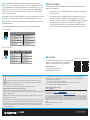
For information about DM OUT and LAN connector wiring, refer to the following illustrations.
DM OUT Connector Wiring
LAN Connector Pin Assignments
DO Set the IP Address
The conguration of the transmitter within the DigitalMedia 8G+
®
system determines how the IP
address of the transmitter is set:
• If the transmitter connects to a DigitalMedia switcher, the transmitter is congured by the
switcher automatically.
• If the transmitter connects to a DigitalMedia 8G+ receiver, the transmitter uses its own
conguration settings. By default, DHCP is enabled. If assignment of the default IP
address to the transmitter is desired, hold down the SETUP button while the unit boots up.
The default IP address overwrites the current setting. The default IP address of the
DM-TX-4KZ-202-C is 192.168.1.251. The default IP address of the DM-TX-4KZ-302-C is
192.168.1.252. To manually set a different IP address, use Crestron Toolbox™ software.
DO Learn More
Visit the website for additional information and the latest rmware
updates. To learn more about this product, use a QR reader
application on your mobile device to scan the QR image.
Crestron Electronics
15 Volvo Drive, Rockleigh, NJ 07647
888.CRESTRON | www.crestron.com
As of the date of manufacture, the product has been tested and found to comply with specications for CE marking.
This product is Listed to applicable UL
®
Standards and requirements tested by Underwriters Laboratories Inc.
Ce produit est homologué selon les normes et les exigences UL applicables par Underwriters Laboratories Inc.
This unit is for indoor use only. It is not intended for outdoor use.
Cet appareil est réservé à une utilisation en intérieur. Il n’est pas destiné à une utilisation en extérieur.
Federal Communications Commission (FCC) Compliance Statement
This device complies with part 15 of the FCC Rules. Operation is subject to the following two conditions:
(1) This device may not cause harmful interference, and (2) this device must accept any interference received, including interference
that may cause undesired operation.
CAUTION: Changes or modications not expressly approved by the manufacturer responsible for compliance could void the
user’s authority to operate the equipment.
NOTE: This equipment has been tested and found to comply with the limits for a Class B digital device, pursuant to part 15 of the
FCC Rules. These limits are designed to provide reasonable protection against harmful interference in a residential installation.
This equipment generates, uses and can radiate radio frequency energy and, if not installed and used in accordance with the
instructions, may cause harmful interference to radio communications. However, there is no guarantee that interference will not
occur in a particular installation.
If this equipment does cause harmful interference to radio or television reception, which can be determined by turning the
equipment off and on, the user is encouraged to try to correct the interference by one or more of the following measures:
• Reorient or relocate the receiving antenna.
• Increase the separation between the equipment and receiver.
• Connect the equipment into an outlet on a circuit different from that to which the receiver is connected.
• Consult the dealer or an experienced radio/TV technician for help.
Industry Canada (IC) Compliance Statement
CAN ICES-3(B)/NMB-3(B)
The specic patents that cover Crestron products are listed at www.crestron.com/legal/patents.
The product warranty can be found at www.crestron.com/legal/sales-terms-conditions-warranties.
Certain Crestron products contain open source software. For specic information, visit www.crestron.com/legal/open-source-software.
Crestron, the Crestron logo, Crestron Toolbox, DigitalMedia, DigitalMedia 8G+, and DM are either trademarks or registered trademarks of Crestron Electronics, Inc. in the United States and/
or other countries. HDBaseT and the HDBaseT Alliance logo are either trademarks or registered trademarks of the HDBaseT Alliance in the United States and/or other countries. HDMI and the
HDMI logo are either trademarks or registered trademarks of HDMI Licensing LLC in the United States and/or other countries. UL and the UL logo are either trademarks or registered trademarks
of Underwriters Laboratories, Inc. in the United States and/or other countries. Other trademarks, registered trademarks, and trade names may be used in this document to refer to either the
entities claiming the marks and names or their products. Crestron disclaims any proprietary interest in the marks and names of others. Crestron is not responsible for errors in typography or
photography.
This document was written by the Technical Publications department at Crestron.
©2017 Crestron Electronics, Inc.
PIN NUM. WIRE COLOR PIN NUM. WIRE COLOR
1 Orange/White 5 Blue/White
2 Orange 6 Green
3 Green/White 7 Brown/White
4 Blue 8 Brown
PIN NUM. SIGNAL PIN NUM. SIGNAL
1 TX+ 5 N/C
2 TX- 6 RX-
3 RX+ 7 N/C
4 N/C 8 N/C
Pin 1Pin 8
Pin 1
Pin 8
DM-TX-4KZ-202-C
DM-TX-4KZ-302-C
-
 1
1
-
 2
2


Crestron DM-TX-4KZ-202-C Mode d'emploi
- Taper
- Mode d'emploi
- Ce manuel convient également à
dans d''autres langues
- English: Crestron DM-TX-4KZ-202-C User guide
Documents connexes
-
Crestron DM-TX-4K-302-C Mode d'emploi
-
-
-
-
Crestron DM-MD64X64 Mode d'emploi
-
-
Crestron HD-EXT-USB-2000-C Mode d'emploi
-
-
-