Kichler Lighting 34712 Manuel utilisateur
- Taper
- Manuel utilisateur

Français p. 13
Español p. 25
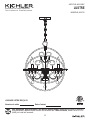
ITEM #0615997
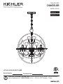
MODEL #34712
CHANDELIER
1
ATTACH YOUR RECEIPT HERE
Serial Number
Purchase Date
Questions, problems, missing parts? Before returning to your retailer, call our customer
service department at 1-800-554-6504, 8 a.m. - 4:30 p.m, EST, Monday - Friday.
Kichler® is a registered trademark of
The L.D. Kichler Co. All Rights Reserved.

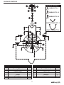
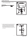
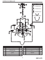
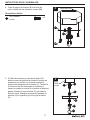
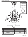
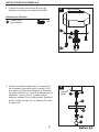
PACKAGE CONTENTS
2
A
Canopy
Mounting Bracket
Threaded Nipple
Hex Nut
Socket
Coupling
Fixture Body
B
C
D
E
F
G
1
1
1
3
6
1
1
PART DESCRIPTION QTY
Screw Collar Ring
Screw Collar Loop
Fixture Loop
Chain
Bobeche
Crystal Loop
I
H
J
K
L
M
1
1
1
1
6
52
PART DESCRIPTION QTY
A
G
B
D
H
K
L
C
I
J
F
E
M
HANGING CRYSTALS
1-BEAD QTY: 6
2-BEAD QTY: 10
4-BEAD QTY: 36
SHORT STRING QTY: 3
LONG STRING QTY: 6

3
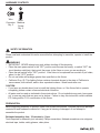
HARDWARE CONTENTS
Wire
Connector
AA
Short
Machine
Screw
BB
Qty: 3
Qty: 2
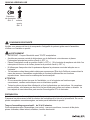
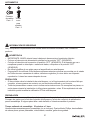
SAFETY INFORMATION
Please read and understand this entire manual before attempting to assemble, operate or install the
product.
WARNING
• IMPORTANT: NEVER attempt any work without shutting off the electricity.
• Place the main power switch in the “OFF” position and unscrew the fuse(s), or switch “OFF” the
circuit breaker switch(es), that control the power to the fixture or room you are working in.
• Place the wall switch in the "OFF" position. If the fixture to be replaced has a switch or pull chain,
place it in the "OFF" position.
• Do not use bulbs with wattage greater than specified on this fixture.
• California Prop. 65: This lighting fixture contains chemicals known to the state of California to
cause cancer, birth defects, and/or other reproductive harm. Wash hands after use.
CAUTION
• If you have any doubts about how to install this lighting fixture, or if the fixture fails to operate
completely, please contact a licensed electrical contractor.
• All parts must be used as indicated in these instructions. Do not substitute any parts, leave parts
out, or use any parts that are worn out or broken. Failure to obey this instruction could invalidate
ETL listing and/or C.S.A. certification of this fixture.
PREPARATION
Before beginning assembly of product, make sure all parts are present. Compare parts with package
contents list and hardware contents list. If any part is missing or damaged, do not attempt to
assemble the product.
Estimated assembly time: 30 minutes to 1 hour
Tools Required for Assembly (not included): Phillips screwdriver, flathead screwdriver, wire strippers,
electrical tape, ladder, safety glasses, chain pliers.

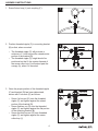
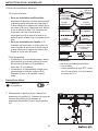
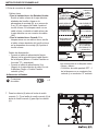
4
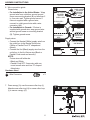
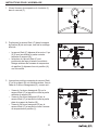
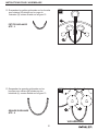
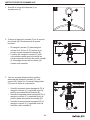
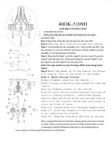
2. Position threaded nipple (C) in mounting bracket
(B) so that, when mounted:
• The threaded nipple (C) will protrude a
minimum of ¼ inch beyond the raised center
portion of the bracket (B).
• The threaded nipple (C) height should be
positioned so that ½ the exterior threads of
the screw collar loop (I) will extend past the
canopy (A), when it is mounted.
3. Once the proper position of the threaded nipple
(C) and bracket (B) has been determined,
secure with 3 hex nuts (D) as follows:
• Screw 1st hex nut (D) onto the threaded
nipple (C) and tighten against the raised
portion of the bracket (B).
• Screw 2nd hex nut (D) onto the threaded
nipple (C) and tighten against the flat portion
of the mounting bracket (B).
• Screw the third hex nut (D) onto threaded
nipple (C) and tighten against the screw
collar loop (I)
3
¼ Inch
D
C
I
B
ASSEMBLY INSTRUCTIONS
1. Screw fixture loop (J) onto coupling (F).
2
B
A
¼ Inch
I
C
1
F
J

ASSEMBLY INSTRUCTIONS
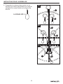
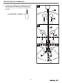
5
Hardware Used
Short Machine
Screw
x 2
BB
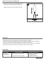
4. Connect mounting bracket (B) to the outlet box
with short machine screws (BB).
4
Outlet Box
C
B
BB
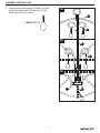
5. Using the open chain links on chain (K), attach one
end to screw collar loop (I) and the other end to
fixture loop (J). Weave the fixture electrical and
ground wires through every other chain link and
pass through threaded nipple (C) into outlet box.
Lower the screw collar ring (H) and canopy (A) over
the chain (K).
J
H
A
K
I
C
5
Outlet
Box

ASSEMBLY INSTRUCTIONS
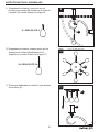
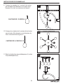
6
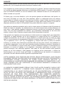
7. Pass canopy (A) over the screw collar loop (I).
Attach screw collar ring (H) to screw collar loop
(I) to secure canopy (A).
Hardware Used
x 3Wire Connector
AA
6. Wire connection guide:
Ground wire:
• For installation in the United States: Wrap
ground wire from outlet box around ground
screw on mounting bracket (B) no less than 2
in. from wire end. Tighten ground screw. If
fixture is supplied with a ground wire,
connect to outlet ground wire with a wire
connector (AA).
• For installation in Canada: If fixture is
supplied with ground wire, wrap ground wire
around ground screw on mounting bracket
(B). Tighten ground screw.
Supply wires:
• Connect the Neutral (White) supply wire from
the outlet box to the Neutral fixture wire
(White or Parallel Cord “D” shaped and
ribbed).
• Connect the Hot (Black) supply wire from the
outlet box to the Hot fixture wire (Black or
Parallel Cord round and smooth).
NOTE:
Fixture wires will either be:
• Black and White.
• Parallel Cord SPT-1 lamp wire with one
round smooth wire and one “D” shaped
ribbed wire.
6
BARE COPPER,
OR GREEN
GROUND
SUPPLY WIRE
BARE COPPER,
OR GREEN
GROUND
FIXTURE
WIRE
BLACK FIXTURE
WIRE
OR
WHITE FIXTURE
WIRE
BLACK SUPPLY
WIRE
BLACK SUPPLY
WIRE
PARALLEL
FIXTURE CORD
(ROUND AND
SMOOTH)
PARALLEL FIXTURE
CORD (“D” SHAPED
AND RIDGED
)
WHITE SUPPLY
WIRE
WHITE SUPPLY
WIRE
AA
7
H
I
A

ASSEMBLY INSTRUCTIONS
7
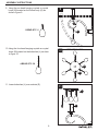
8. Hang the two bead hanging crystals on crystal
loops (M) located on the fixture body (G) as
show in figure 8a, 8b, and 8c.
2-BEAD QTY: 10
8b
8a
G
G
M
M
M
G
8c

8
ASSEMBLY INSTRUCTIONS
9. Hang the one bead hanging crystals on crystal
loops (M) located on the fixture body (G) as
show in figure 9.
M
G
9
1-BEAD QTY: 6
10. Hang the four bead hanging crystals on crystal
loops (M) located on the bobeches (L) as show
in figure 10.
11. Lower bobeches (L) over sockets (E).
4-BEAD QTY: 36
10
TOP DOWN VIEW
L
M
11
L
E

9
ASSEMBLY INSTRUCTIONS
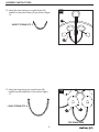
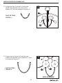
12. Hang the short strings on crystal loops (M)
located on the fixture body (G) as show in figure
12.
SHORT STRING QTY: 3
13. Hang the long strings on crystal loops (M)
located on the bobeches (L) as show in figure
13.
L
M
TOP DOWN VIEW
13
LONG STRING QTY: 6
G
M
12

10
ASSEMBLY INSTRUCTIONS
TROUBLESHOOTING
Fixture does not light. 1. Fixture may be wired incorrectly.
1. Check wiring.
2. Worn or broken bulb. 2. Replace bulb.
1. Check wiring.
PROBLEM POSSIBLE CAUSE CORRECTIVE ACTION
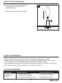
• Always be certain that electric current is turned off before cleaning this item.
• Use a soft, moist cloth with mild non-abrasive soap to clean fixture. Never use glass cleaner on
fixture, as it will damage the metal finish.
• All glass shades may be washed in a towel-lined sink with warm water and mild soap. Do not
wash shades in an automatic dishwasher.
CARE AND MAINTENANCE
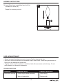
14. Insert 60-watt max. candelabra-base bulb (not
included) into socket (E).
Repeat for remaining sockets.
E
14

Kichler Lighting warrants that its products will be free from defects in material and workmanship for
one (1) year from the date of purchase by the Original Purchaser.
To replace a product that has a warranted defect, the Original Purchaser shall return any allegedly
defective parts or products to the authorized Kichler distributor that the product was purchased from
with PROOF OF PURCHASE, Original Purchaser’s name and return address and a description of the
claimed product defect.
If any of the warranted products are found by Kichler, in its sole discretion, to be defective, such
products will, at Kichler’s sole option and cost, be replaced, repaired or refunded less an amount
directly attributable to Original Purchaser’s prior use of the product. Kichler will return the repaired or
replaced product prepaid freight. This warranty does not cover labor or other costs or expenses to
remove or install any defective, repaired or replaced product.
The parties hereto expressly agree that Original Purchaser’s sole and exclusive remedy against
Kichler shall be for the repair, replacement or refund of defective products as provided herein. This
warranty extends only to product ownership by the Original Purchaser; is not transferable whether to
heirs, subsequent owners, or otherwise; and is void if the Original Purchaser ceases to own the
product.
This warranty does not apply to any products that have been subjected to misuse, mishandling,
misapplication, connected to voltage at more than 5% above standard North American voltage,
unusual use (including but not limited to use in an environment where the annual average ambient
operating temperature is below 27 or above 95 degrees Fahrenheit), neglect (including but not limited
to improper maintenance), accident, acts of god such as high winds, improper installation or care,
failure to follow the Product’s written instructions for normal use and care, improper packaging of
products returned to Kichler, modification (including but not limited to use of unauthorized parts or
attachments), or adjustment or repair. Significant product exposure to chemicals, harsh cleaners, salt
water or salt air will void any and all warranties on exterior finishes. This warranty only applies when
all components, including transformers, have been provided by Kichler. Substituting another
manufacturer’s product and/or components will render the warranty completely void.
THIS WARRANTY GIVES YOU SPECIFIC LEGAL RIGHTS. YOU MAY ALSO HAVE OTHER
RIGHTS, WHICH VARY FROM STATE TO STATE. SOME STATES DO NOT ALLOW LIMITATIONS
ON HOW LONG AN IMPLIED WARRANTY LASTS OR THE EXCLUSION OR LIMITATION OF
INCIDENTAL OR CONSEQUENTIAL DAMAGES SO THE ABOVE LIMITATIONS OR EXCLUSIONS
MAY NOT APPLY TO YOU.
THE FOREGOING WARRANTY IS IN LIEU OF ALL OTHER WARRANTIES, EXPRESS OR
IMPLIED, INCLUDING THOSE OF MERCHANTABILITY, FITNESS FOR ANY PARTICULAR
PURPOSE OR INFRINGEMENT. ORIGINAL PURCHASER SHALL IN NO EVENT BE ENTITLED
TO, AND KICHLER LIGHTING SHALL NOT BE LIABLE FOR, INDIRECT, SPECIAL, INCIDENTAL
OR CONSEQUENTIAL DAMAGES OF ANY NATURE, INCLUDING, BUT NOT LIMITED TO LOSS
OF PROFIT, PROMOTIONAL AND/OR MANUFACTURING EXPENSES, OVERHEAD, INJURY TO
REPUTATION AND/OR LOSS OF CUSTOMERS.
WARRANTY
11

Rev. 01-16-18
Kichler® is a registered trademark of
The L.D. Kichler Co. All Rights Reserved
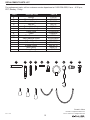
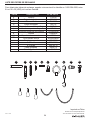
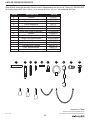
REPLACEMENT PARTS LIST
For replacement parts, call our customer service department at 1-800-554-6504, 8 a.m. - 4:30 p.m.,
EST, Monday - Friday.
Printed in China
A
B
C
D
H
I
J
K
AA
BB
Canopy C34706
Mounting Bracket XBAR01
Threaded Nipple TN18200
Hex Nut NUT18
Screw Collar Ring SCG-NI
Screw Collar Loop SCL-NI
Fixture Loop TLOOP05-NI
Chain CHAIN-NI
Wire Connector WC001
Short Machine Screw SCR832X050
1-Bead Crystal 1BC34712
2-Bead Crystal 2BC34712
4-Bead Crystal 4BC34712
Short String SS34712
Long String LS34712
PART DESCRIPTION PART #
A B
C
D
H I
BBAA
K
J
12

ARTICLE #0615997
MODÈLE #34712
LUSTRE
13
Kichler® est une marque déposée de
The L.D. Kichler Co. Tous droits réservés.
Des questions, des problèmes, des pièces manquantes? Avant de retourner le produit à
votre détaillant, appelez notre service à la clientèle au 1-800-554-6504, entre 8 h et 16 h 30
(HNE) du lundi au vendredi.
JOIGNEZ VOTRE REÇU ICI
Numéro de série
Date d’achat

CONTENU DE L’EMBALLAGE
14
A
Pavillon
Support de fixation
Raccord fileté
Écrou hexagonal
Douille
Raccord
Corps du luminaire
B
C
D
E
F
G
1
1
1
3
6
1
1
PIÈCE
DESCRIPTION QT
È
Bague de l'anneau du pavillon
Anneau de suspension du pavillon
Anneau de suspension du luminaire
Chaîne
Bobèche
Boucle pour cristal
I
H
J
K
L
M
1
1
1
1
6
52
PIÈCE
DESCRIPTION QT
È
A
G
B
D
H
K
L
C
I
J
F
E
M
CRISTAUX SUSPENDUS
À 1 PERLES QTÉ: 6
À 2 PERLES QTÉ: 10
À 4 PERLES QTÉ: 36
PETITE GUIRLANDE QTÉ : 3
GRANDE GUIRLANDE QTÉ : 6

15
QUINCAILLERIE INCLUSE
Capuchon
de connexion
AA
Vis à
métaux
courte
BB
Qté : 3
Qté : 2
CONSIGNES DE SÉCURITÉ
Veuillez vous assurer de lire et de comprendre l’intégralité du présent guide avant d’assembler,
d’utiliser ou d’installer ce produit.
AVERTISSEMENT
• IMPORTANT : Coupez l’électricité avant TOUTE manipulation.
• Accédez au panneau central de disjoncteurs ou de fusibles de votre demeure et placez
l’interrupteur principal en position d’arrêt (« OFF »).
• Placez l’interrupteur mural en position d’arrêt (« OFF »). Si le luminaire à remplacer est doté d’un
interrupteur à bouton ou à chaîne, placez-le en position d’arrêt (« OFF »).
• N’utilisez pas d’ampoules dont la puissance dépasse la puissance nominale indiquée sur ce
luminaire.
• Ce luminaire contient des produits chimiques reconnus par l’État de la Californie comme étant la
cause de cancers, d’anomalies congénitales et d’autres problèmes liés aux fonctions
reproductrices. Lavez-vous les mains après l’avoir manipulé.
ATTENTION
• Si vous avez des doutes à propos de l’installation, ou si le luminaire ne fonctionne pas
correctement, veuillez communiquer avec un électricien qualifié.
• Toutes les pièces doivent être utilisées tel qu’il est indiqué dans ces instructions. Ne remplacez
pas les pièces, n'en laissez pas de côté et ne les utilisez pas si elles sont usées ou brisées. Le
non-respect de ces instructions peut annuler l’homologation ETL du luminaire.
PRÉPARATION
Avant de commencer l’assemblage du produit, assurez-vous que toutes les pièces sont présentes.
Comparez les pièces avec la liste du contenu de l’emballage et la liste de la quincaillerie. En cas de
pièces manquantes ou endommagées, ne tentez pas d’assembler le produit.
Temps d’assemblage approximatif : de 30 à 60 minutes.
Outils nécessaires pour l’assemblage (non inclus) : tournevis cruciforme, tournevis à tête plate,
pinces à dénuder, ruban isolant, escabeau, lunettes de sécurité.

16
3
¼ po
D
C
I
B
2
B
A
¼ po
I
C
1
F
J
INSTRUCTIONS POUR L'ASSEMBLAGE
1. Vissez l'anneau de suspension du luminaire (J)
dans le raccord (F).
2. Positionnez le raccord fileté (C) dans le support
de fixation (B) de sorte que, une fois le montage
effectué :
• le raccord fileté (C) dépasse d'au moins ¼ po
(6,35 mm) au-delà de la partie centrale
saillante du support (B) ;
• la hauteur du raccord fileté (C) soit
positionnée de façon à laisser la moitié du
filetage extérieur de l'anneau de suspension
du pavillon (I) dépasser hors du pavillon (A),
une fois monté.
3. Lorsque les positions correctes du raccord fileté
(C) et du support (B) ont été déterminées, fixez à
l'aide de 3 écrous hexagonaux (D), comme suit :
• Vissez le 1er écrou hexagonal (D) sur le
raccord fileté (C) et serrez-le contre la partie
saillante du support (B).
• Vissez le 2e écrou hexagonal (D) sur le
raccord fileté (C) et serrez-le contre la partie
plate du support de fixation (B).
• Vissez le 3e écrou hexagonal (D) sur le
raccord fileté (C) et serrez-le contre l'anneau
de suspension du pavillon (I).

17
4
Boîte de sortie
C
B
BB
J
H
A
K
I
C
5
Boîte de
sortie
INSTRUCTIONS POUR L'ASSEMBLAGE
5. À l'aide des anneaux ouverts de la chaîne (K),
attachez une extrémité de la chaîne à l'anneau de
suspension du pavillon (I) et l'autre extrémité à
l'anneau de suspension du luminaire (J). Tressez le
fil de terre et les fils électriques du luminaire à
travers un maillon sur deux de la chaîne et faites-les
passer à travers le raccord fileté (C) puis dans la
boîte de sortie. Abaissez la bague de l'anneau du
pavillon (H) et le pavillon (A) le long de la chaîne
(K).
4. Fixez le support de fixation (B) à la boîte de
sortie à l'aide des vis à métaux courtes (BB).
Vis à métaux
courte
x 2BB
Quincaillerie utilisée

18
7
H
I
A
INSTRUCTIONS POUR L'ASSEMBLAGE
Quincaillerie utilisée
AA
x 3
6.Guide de raccordement électrique
Fil de mise à la terre :
• Pour une installation aux États-Unis :
enroulez le fil de mise à la terre provenant de
la boîte de sortie autour de la vis de mise à
la terre située sur le support de fixation (B), à
au moins 5,08 cm de l’extrémité du fil. Serrez
la vis de mise à la terre. Si le luminaire est
fourni avec un fil de mise à la terre,
raccordez-le au fil de mise à la terre de la
boîte de sortie à l’aide d’un connecteur de fils
(AA).
• Pour une installation au Canada : si le
luminaire est fourni avec un fil de mise à la
terre, enroulez-le autour de la vis de mise à
la terre située sur le support de fixation (B).
Serrez la vis de mise à la terre.
Fils d'alimentation :
• Connectez le fil neutre d’alimentation (blanc)
provenant de la boîte de sortie au fil neutre
du luminaire (fil blanc ou fil parallèle en
forme de « D » et rainuré).
• Connectez le fil d’alimentation chargé (noir)
provenant de la boîte de sortie au fil du
luminaire (fil noir ou fil parallèle, rond et
lisse).
Capuchon
de connexion
REMARQUE :
Les fils du luminaire peuvent être :
• noir et blanc;
• cordon parallèle de type SPT-1 muni
d’un fil rond et lisse et d’un fil rainuré
en forme de « D ».
6
CUIVRE NU, OU
FIL VERT DE MISE
À LA TERRE
DE LA RÉSIDENCE
CUIVRE NU, OU FIL VERT DE
MISE À LA
TERRE DU
LUMINAIRE
FIL NOIR
DU LUMINAIRE
OU
FIL BLANC
DU LUMINAIRE
FIL NOIR
D'ALIMENTATION
FIL NOIR
D'ALIMENTATION
FIL DU CÂBLE
PARALLÈLE DU
LUMINAIRE
(ROND ET LISSE
)
FIL DU CÂBLE
PARALLÈLE DU LUMINAIRE
(EN FORME DE « D »
ET RAINURÉ)
FIL BLANC
D'ALIMENTATION
FIL BLANC
D'ALIMENTATION
7. Faites passer le pavillon (A) sur l'anneau de
suspension du pavillon (I). Attachez la bague de
l'anneau du pavillon (H) à l'anneau de
suspension du pavillon (I) pour fixer le pavillon
(A).

INSTRUCTIONS POUR L'ASSEMBLAGE
19
8. Suspendez les cristaux à deux perles sur les
boucles pour cristaux (M) situées sur le corps du
luminaire (G) comme illustré sur les figures 8a,
8b et 8c.
À 2 PERLES QTÉ: 10
8b
8a
G
G
M
M
M
G
8c

20
INSTRUCTIONS POUR L'ASSEMBLAGE
9. Suspendez les cristaux à une perle sur les
boucles pour cristaux (M) situées sur le corps du
luminaire (G) comme illustré sur la figure 9.
M
G
9
À 1 PERLES QTÉ: 6
10. Suspendez les cristaux à quatre perles sur les
boucles pour cristaux (M) situées sur les
bobèches (L) comme illustré sur la figure 10.
11.
Placez les bobèches de douille (L) par-dessus
les douilles (E).
À 4 PERLES QTÉ: 36
10
VUE AÉRIENNE
L
M
11
L
E
La page est en cours de chargement...
La page est en cours de chargement...
La page est en cours de chargement...
La page est en cours de chargement...
La page est en cours de chargement...
La page est en cours de chargement...
La page est en cours de chargement...
La page est en cours de chargement...
La page est en cours de chargement...
La page est en cours de chargement...
La page est en cours de chargement...
La page est en cours de chargement...
La page est en cours de chargement...
La page est en cours de chargement...
La page est en cours de chargement...
La page est en cours de chargement...
-
 1
1
-
 2
2
-
 3
3
-
 4
4
-
 5
5
-
 6
6
-
 7
7
-
 8
8
-
 9
9
-
 10
10
-
 11
11
-
 12
12
-
 13
13
-
 14
14
-
 15
15
-
 16
16
-
 17
17
-
 18
18
-
 19
19
-
 20
20
-
 21
21
-
 22
22
-
 23
23
-
 24
24
-
 25
25
-
 26
26
-
 27
27
-
 28
28
-
 29
29
-
 30
30
-
 31
31
-
 32
32
-
 33
33
-
 34
34
-
 35
35
-
 36
36


Kichler Lighting 34712 Manuel utilisateur
- Taper
- Manuel utilisateur
dans d''autres langues
- English: Kichler Lighting 34712 User manual
- español: Kichler Lighting 34712 Manual de usuario
Documents connexes
-
 Kichler Lighting 34713 Manuel utilisateur
-
Kichler 34710 Manuel utilisateur
-
 Kichler Lighting 34723 Manuel utilisateur
-
-
 Kichler Lighting 34722 Manuel utilisateur
-
 Kichler Lighting 34724 Manuel utilisateur
-
-
-
 Kichler Lighting 34837 Manuel utilisateur
-
 Kichler Lighting 34838 Manuel utilisateur


Autres documents
-
-
-
SpinMaster Twisty Petz Le manuel du propriétaire
-
 HomeSullivan 40OK-5109H Guide d'installation
-
-
Decor Therapy CH1950 Guide d'installation
-
-
Warehouse of Tiffany RL8070 Guide d'installation
-
-
GE Holiday 389446 Manuel utilisateur
