
MICROWAVE HOOD COMBINATION
INSTALLATIONINSTRUCTIONS
This product is suitable for use above electric or gas cooking products up to and including 36" (91.4 cm) wide. See "Installation
Requirements" section for further notes.
These installation instructions cover different models. The appearance of your particular model may differ slightly from the illustration in
these installation instructions.
INSTRUCTIONSD'INSTALLATION
DEL'ENSEMBLEFOUR MICRO-ONDES/HOTTE
Ce produit est con£;u pour I'utilisation au-dessus d'appareils de cuisson electriques ou &gaz de 36" (91,4 cm) de largeur ou moins. Voir
la section "Exigences d'installation" pour d'autres remarques.
Ces instructions d'installation sont valables pour plusieurs modeles. IIse peut que I'apparence de votre propre modele soit legerement
differente de celle montree sur les illustrations dans ce document.
Table ofContents / Tabledes mati@res
MICROWAVE HOOD COMBINATION SAFETY ...................... 1
INSTALLATION REQUIREMENTS ........................................... 2
Tools and Parts ......................................................................2
Remove Cardboard Template ............................................... 2
Location Requirements .......................................................... 2
Product Dimensions .............................................................. 3
Electrical Requirements ........................................................ 3
INSTALLATION INSTRUCTIONS ............................................. 4
Remove Mounting Plate ......................................................... 4
Rotate Blower Motor .............................................................. 4
Locate Wall Stud(s) ................................................................ 6
Mark Rear Wall ....................................................................... 7
Drill Holes in Rear Wall ........................................................... 7
Attach Mounting Plate to Wall ............................................... 8
Prepare Upper Cabinet .......................................................... 8
Install Damper Assembly ....................................................... 9
Install the Microwave Oven .................................................... 9
Complete Installation ........................................................... 10
VENTING DESIGN SPECIFICATIONS ................................... 11
ASSISTANCE ........................................................................... 12
Replacement Parts ............................................................... 12
Accessories .......................................................................... 12
SECURITE DE L'ENSEMBLE FOUR .&.MICRO-ONDES/HOTTE...13
EXIGENCES D'INSTALLATION ......................................................... 13
Outillage et pieces ........................................................................... 13
Depose du gabarit de carton .......................................................... 14
Exigences d'emplacement .............................................................. 14
Dimensions du produit ................................................................... 14
Specifications electriques ............................................................... 15
INSTRUCTIONS [:)'INSTALLATION .................................................. 15
Depose de la plaque de montage ................................................... 15
Reorientation du moteur du ventilateur .......................................... 15
Identifier la position du/des poteau(x) du colombage mural .......... 17
Trace sur le mur arriere ................................................................... 18
Pergage de trous dans lemur arriere .............................................. 19
Fixation de la plaque de montage sur lemur ................................. 19
Preparation du placard superieur ................................................... 20
Installation du module du clapet anti-reflux .................................... 21
Installation du four & micro-ondes .................................................. 21
Achever I'installation ........................................................................ 22
SPECIFICATIONS/CONCEPTION DU CIRCUIT D'E'VACUATION ........23
ASSISTANCE ...................................................................................... 24
Pieces de rechange ......................................................................... 24
Accessoires ..................................................................................... 24
MICROWAVE HOOD COMBINATION SAFETY
Your safety and the safety of others are very important.
We have provided many important safety messages in this manual and on your appliance. Always read and obey all safety
messages.
This is the safety alert symbol.
This symbol alerts you to potential hazards that can kill or hurt you and others.
All safety messages will follow the safety alert symbol and either the word "DANGER" or "WARNING."
These words mean:
You can be killed or seriously injured if you don't immediately
follow instructions.
You can be killed or seriously injured if you don't follow
instructions.
All safety messages will tell you what the potential hazard is, tell you how to reduce the chance of injury, and tell you what can
happen if the instructions are not followed.
IIIllllIIIilllllllllllllllliiIllIIIll
W10644783A

INSTALLATIONREQUIREMENTS
®rid Pa#s
Tools Needed
Gather the required tools and parts before starting installation.
Read and follow the instructions provided with any tools
listed here.
• Measuring tape • Diagonal wire cutting pliers
• Pencil • Stud finder
• Masking tape or thumbtacks • 7/16" socket wrench
(or box wrench) for 1/4" x 2"
• Scissors lag screws
• No. 2 Phillips screwdriver
• 11/2'' (3.8 cm) diam. hole drill
• No. 3 Phillips screwdriver for bit for wood or metal
1/4-20 x 3" bolts cabinet
• Drill • Keyhole saw
• 3/16" (5 mm), 3/8" (10 mm) • Caulking gun and
drill bits weatherproof caulking
compound
• 3/4" (19 mm) hole saw
Duct tape
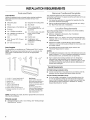
Parts Supplied
For information on reordering, see "Replacement Parts" section.
NOTE: The hardware items listed here are for wood studs. For
other types of wall structures, be sure to use appropriate
fasteners.
A
A 1/4-20 x 3" round-head bolts (2)
B. 1/4-20 x 3" flat-head bolts (2)
C. Washers (2)
D. Toggle nuts (2)
E. 1/4" x 2" lag screws (2)
E Sheet metal screws (2)
G. Power supply cord bushing (1)
H. Damper assembly (for wall or roof
venting)
Not Shown:
Upper cabinet template
Mounting plate (attached to
back of microwave oven)
Cardboard template (part of
packaging)
Aluminum grease filters
Charcoal filters (Depending
on model, charcoal filters
may not be included. See
User Instructions.)
NOTE: Depending on model, aluminum grease filter and charcoal
filter may be combined.
Materials needed
• Standard fittings for wall or roof venting. See "Venting Design
Specifications" section.
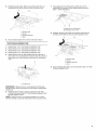
Remove CG db rd @mp ®te
The cardboard piece from the top of the microwave oven
packaging is perforated. The piece inside the perforation is for use
as a rear wall template.
1. Cut along the perforation to separate the template from the
rest of the cardboard packaging.
2. Set the cardboard template to the side and refer to it during
the "Mark Rear Wall" part of installation.
Location Requirements
Check the opening where the microwave oven will be installed.
The location must provide:
• Minimum installation dimensions. See "Installation
Dimensions" illustration.
Minimum one 2" x 4" (50.8 x 101.6 mm) wood wall stud and
minimum 3/8" (10 mm) thickness drywall or plaster/lath within
cabinet opening.
Support for weight of 150 Ibs (68 kg), which includes
microwave oven and items placed inside the microwave oven
and upper cabinet.
Grounded electrical outlet inside upper cabinet. See
"Electrical Requirements" section.
NOTES:
• If installing the microwave oven near a left sidewall, make sure
there is at least 6" (15.2 cm) of clearance between the wall and
the microwave oven, so that the door can open fully.
Some cabinet and building materials are not designed to
withstand the heat produced by the microwave oven for
cooking. Check with your builder or cabinet supplier to make
sure that the materials used will not discolor, delaminate or
sustain other damages.
Special Requirements
For Wall Venting Installation Only:
• Cutout must be free of any obstructions so that the vent fits
properly, and the damper blade opens freely and fully.
For Roof Venting Installation Only:
• If you are using a rectangular to round transition piece, the
3" (7.6 cm) clearance needs to exist above the microwave
oven so that the damper blade can open freely and fully. See
"Rectangular to Round Transition" illustration in "Venting
Design Specifications" section.
2

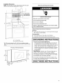
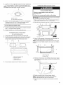
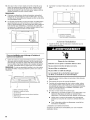
Installation Dimensions
NOTE: The grounded 3 prong outlet must be inside the upper
cabinet. See "Electrical Requirements" section.
A B
12" (30.5 crn) rain.
(35.6 cm) max.
upper cabinet and
side cabinet depth
A. 2" x 4" wall stud
B. Grounded 3 prong outlet
*30" (76.2 cm) is typical for 66" (167.6 cm) installation height.
Exact dimensions may vary depending on type of range/cooktop
below.
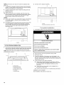
? odu@ Dimensions
E ÷@ icd £®qui ®m÷n s
Electrical Shock Hazard
Plug into a grounded 3 prong outlet.
Do not remove ground prong.
Do not use an adapter.
Do not use an extension cord.
Failure to follow these instructions can result in death,
fire, or electrical shock.
Observe all governing codes and ordinances.
Required:
[] A 120 volt, 60 Hz, AC only, 15- or 20-amp electrical supply
with a fuse or circuit breaker.
Recommended:
[] A time-delay fuse or time-delay circuit breaker.
[] A separate circuit serving only this microwave oven.
GROUNDING iNSTRUCTiONS
[] For all cord connected appliances:
The microwave oven must be grounded. In the event of
an electrical short circuit, grounding reduces the risk of
electric shock by providing an escape wire for the electric
current. The microwave oven is equipped with a cord
having a grounding wire with a grounding plug. The plug
must be plugged into an outlet that is properly installed
and grounded.
WARNING: Improper use of the grounding plug can
result in a risk of electric shock. Consult a qualified
electrician or serviceman if the grounding instructions are
not completely understood, or if doubt exists as to whether
the microwave oven is properly grounded.
Do not use an extension cord. If the power supply cord is
too short, have a qualified electrician or serviceman install
an outlet near the microwave oven.
SAVE THESE iNSTRUCTiONS

INSTALLATIONINSTRUCTIONS
Remove Mounting P ate
Depending on your model, the mounting plate may be in the foam
packaging, or it may be attached to the back of the microwave
oven.
NOTE: To avoid possible damage to the work surface, cover the
work surface.
1. Remove any remaining contents from the microwave oven
cavity.
2. If the mounting plate is attached to the back of the microwave
oven, remove it and set it aside.
3. Tape the microwave oven door closed so that door does not
swing open while the microwave oven is being handled.
NOTE: To avoid damage to the microwave oven, do not grip or
use the door or door handle while the microwave oven is being
handled.
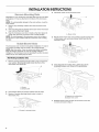
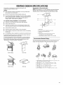
4. Lift blower motor out of microwave oven.
A
5.
A. Blower motor
Rotate blower motor 180 ° so that exhaust ports face the back
of microwave oven, and lower blower motor back into the
microwave oven.
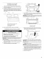
Rotate B ower Motor
The microwave oven is set for recirculation installation. For wall or
roof venting, changes must be made to the venting system.
NOTE: Skip this section if you are using recirculation installation.
Keep the damper assembly in case the venting method is
changed, or the microwave oven is reinstalled in another location
where wall or roof venting may be used.
A
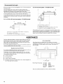
Wall Venting Installation Only
1.
Remove screws attaching damper plate to top of microwave
oven exterior. Slide damper plate toward the front of the
microwave oven and lift up.
.................................A
r;
i
6.
A. Exhaust port
Using diagonal wire cutting pliers, gently snip out the
rectangular damper vent covers at the perforations.
2.
3.
A.Screws
B.Damperplate
Keep damper plate and screws together and set aside.
Remove 2 screws attaching blower motor to back of
microwave oven.
A
A. Screws (in recessed holes)
7,
\/
A
S '""--
A.Diagonalwire cutting pliers
B.Damper vent covers
Reattach blower motor to back of microwave oven with
2 screws removed in Step 3.

8=
Reattach damper plate. Make sure damper plate tabs are
inserted into the slots in the top of the microwave oven.
B
D
A.Damper plate
B.Screws
C.Damperplate tabs
D.Slots
9. Securedamper platewith 2 screws removed inStep 1.
Roof Venting Installation Only
1. Repeat Step 1 from "Wall Venting Installation Only."
2. Repeat Step 2 from "Wall Venting Installation Only."
3. Repeat Step 3 from "Wall Venting Installation Only."
4. Repeat Step 4 from "Wall Venting Installation Only."
5. Rotate blower motor so that exhaust ports face the top of
microwave oven, and flat sides of blower motor face back of
microwave oven. Lower blower motor back into microwave
oven.
A
7. Using diagonal wire cutting pliers, gently snip out the
rectangular vent covers on the damper plate removed in
Step 1, at the perforations.
8=
A B
A. Diagonal wire cutting pliers
B. Rectangular vent covers
Reattach damper plate. Make sure damper plate tabs are
inserted into the slots in the top of the microwave oven.
A B
I
9=
D
--...
A. Damper plate
B. Screws
C. Damper plate tabs
D. Slots
Secure damper plate with 2 screws removed in Step 1 of "Wall
Venting Installation Only."
A. Exhaust port
IMPORTANT: If blower motor is not positioned with flat sides
facing the back of the microwave oven (as shown), performance
will be poor.
6. Reattach blower motor to back of microwave oven with
2 screws removed in Step 3 of "Wall Venting Installation Only."
Securely tighten screws.
NOTE: If blower motor is not correctly oriented, the 2 screws
removed in Step 3 cannot be reattached to the microwave oven.

Locate Stud(s)
NOTE: If no wail studs exist within the cabinet opening, do not 1. Using a stud finder, locate the edges of the wall stud(s) within
install the microwave oven• the opening•
See illustrations in "Possible Wall Stud Configurations." 2. Mark the center of each stud, and draw a plumb line down
each stud center• See illustrations in "Possible Wall Stud
Configurations."
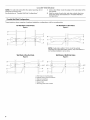
Possible Wall Stud Configurations
These depictions show examples of preferred installation configurations with the mounting plate.
No Wall Studs at End Holes
Figure 1
No Wall Studs at End Holes
Figure2
B
l
}
o................................
i
}
u
I
u
i
m
i
i
J
i
D B '
C
i ;i
i i
NOTE: If wall stud is within 6" (15.2 cm) of the vertical
centerline (see "Mark Rear Wall" section), only recirculation or
roof venting installation can be done.
B
Wall Stud at One End Hole
Figure3
i i i i
i D ;
' i B
!
Wall Studs at Both End Holes
Figure4
1
i
i
i
F
i
A. End holes (on mounting plate)
B. Cabinet opening vertical centerline
C. Waft stud centerlines
D. Holes for lag screws
E. Support tabs
F. Mounting plate center markers
6

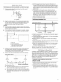
MGrR ReG
The microwave oven must be installed on a minimum of 1 wall
stud, preferably 2, using a minimum of 1 lag screw, preferably 2.
1. Using measuring tape, find and clearly mark the vertical
centerline of the opening.
A ......................JJ/I o1_
A. Centerline
2. Align the center markers on the cardboard template (carton
top cap) to the centerline on the wall, making sure it is level,
and that the top of the cardboard template is butted up
against the bottom edge of the upper cabinet.
NOTES:
• If the front edge of the upper cabinet is lower than the back
edge, lower the cardboard template so that its top is level with
the front edge of the cabinet.
• If the cardboard template is damaged or unusable, measure
and mark the wall with the dimensions described in Step 4.
I
.ll...........................v
A ...............................................................................................
C
B
A. Rear wall
B. Cardboard template
C. Top of cardboard template must
align with front edge of cabineL
D. Front edge of upper cabinet
3. Holding the cardboard template in place, mark both holes in
the lower corners, and draw a horizontal line across the
bottom edge of the cardboard template. These represent the
mounting plate's end holes and bottom edge.
4. Remove the cardboard template and check the markings:
Upper cabinet bottom
15%" Centerline 171/4"
(40.0 crn) ; (43.8 cm)
C ' E
i
141/8,, i 141/a. _
/1 (35.9 i --(35.9ore>
,,,,/_._.L.............................'r...................................'2.........
i Bottom of mounting plate
Mounting plateend hole ,
The bottom edge line must be 171/4'' (43.8 cm) from the
bottom of the upper cabinet, and must be level.
The end holes must be 153/4'' (40.0 cm) from the bottom
edge of the upper cabinet, and must be on a level line with
each other. They must each be 141/8'' (35.9 cm) from the
centerline.
5. With the support tabs facing forward (see illustrations in
"Locate Wall Stud(s)" section), align the mounting plate center
markers to the centerline on the wall, making sure its bottom
edge is aligned to the horizontal line drawn in Step 3, and that
the end holes are properly marked. Make sure the mounting
plate is level.
6. Holding the mounting plate in place, find the wall stud
centerline(s) drawn in Step 2 of "Locate Wall Stud(s)," and
mark at least 1, preferably 2 hole(s) through the mounting
plate, closest to the wall stud centerline(s). See figures 1, 2
and/or 3 in "Possible Wall Stud Configurations" in "Locate
Wall Stud(s)" section. The blackened holes in the shaded
areas are ideal hole locations.
7. Set the mounting plate aside.
Wall Venting Installation Only
Upper cabinet bottom
_%" (1 cm)
8.
9.
10.
11.
12.
13.
14.
f f
4" (10.2 cm) Centerline
* I
6" (15.2 cm) 6" (15.2 cm)
Mark the centerline 3/8" (1 cm) down from the bottom edge of
the upper cabinet.
Using measuring tape, measure out 6" (15.2 cm) on both sides
of the centerline, and mark.
Measure down 4" (10.2 cm) from the mark made in Step 8,
and mark.
Using a straightedge, draw the 2 horizontal, level lines through
the marks made in steps 8 and 10.
Draw the 2 vertical, plumb lines down from the marks made in
Step 9 to complete the 12" x 4" (30.5 x 10.2 cm) rectangle.
This is the venting cutout area.
Cut a 3/4" (19 mm) hole in one corner of the cutout area.
Using a keyhole saw, cut out the venting cutout area.
So es in Rea
In addition to being installed on at least 1 wall stud, the mounting
plate must attach to the wall at both end holes. If the end holes
are not over wall studs, use two 1/4-20 x 3" round-head bolts with
toggle nuts; if 1 end hole is over a wall stud, use 1 lag screw and
one 1/4-20 x 3" round-head bolt with toggle nut; or if both end
holes are over wall studs, use 2 lag screws. Following are 3
installation configurations.
Installation for No Wall Studs at End Holes
(Figures I and 2)
1=
2.
Drill 3/4" (19 mm) holes through the wall at both end holes
marked in Step 3 of "Mark Rear Wall."
Drill 3/16" (5 mm) hole(s) into the wall stud(s) at the hole(s)
marked in Step 6 of "Mark Rear Wall." Refer to figures 1 and 2
in "Possible Wall Stud Configurations" in "Locate Wall Stud(s)"
section.

Installation for Wall Stud at One End Hole (Figure 3)
1. Drill a 3/16" (5 mm) hole into the wall stud at the end hole
marked in Step 3 of "Mark Rear Wall."
2. If installing on a second wall stud, drill a3/16" (5 mm) hole into
the wall stud at the other hole marked in Step 6 of "Mark Rear
Wall." Refer to Figure 3 in "Possible Wall Stud Configurations"
in "Locate Wall Stud(s)" section.
3. Drill a 3/4" (19 mm) hole through the wall at the other end hole.
Installation for Wall Studs at Both End Holes (Figure 4)
1. Drill 3/16" (5 mm) holes into the studs at the end holes marked
in Step 3 of "Mark Rear Wall."
A#GcB Mounting P @e to
NOTE: Secure the mounting plate to the wall at both end holes
drilled into the wall studs and/or drywall using either 1/4-20 x 3"
round-head bolts and toggle nuts or 1/4 x 2" lag screws.
Refer to illustrations in "Possible Wall Stud Configurations" in
"Locate Wall Stud(s)" section.
No Wall Studs at End Holes (Figures 1 and 2)
NOTE: The mounting plate must be secured to the wall on at least
1 wall stud as well as at both ends.
1. With the support tabs of the mounting plate facing forward,
insert 1/4-20 x 3" round-head bolts through both end holes of
mounting plate.
2. Start toggle nuts on bolts from the back of the mounting plate.
Leave enough space for the toggle nuts to go through the wall
and to open.
A
A. 1/4-20 x 3" round-head bolt
B. Mounting plate
C. Spring toggle nut
3=
4.
Position mounting plate on the wall.
Push the 2 bolts with toggle nuts through the drywall, and
finger tighten the bolts to make sure toggle nuts have opened
against drywall.
5=
//
//
//
//
grrm
//
//
//
//
//
D
A. 1/4-20 x 3" round-head bolt
B. Mounting plate
C. Spring toggle nut
D. Drywafl
Insert lag screw(s) into the hole(s) drilled into wall stud(s) in
Step 2 of "Installation for No Wall Studs at End Holes" in the
"Drill Holes in Rear Wall" section.
6. Check alignment of mounting plate, making sure it is level.
7. Securely tighten all lag screws and bolts.
Wall Stud at One End Hole (Figure 3)
1=
With the support tabs of the mounting plate facing forward,
insert a 1/4-20 x 3" round-head bolt through the end hole that
fits over the 3/4" (19 mm) hole drilled in Step 3 of "Installation
for Wall Stud at One End Hole" in the "Drill Holes in Rear Wall"
section.
2. Start a toggle nut on the bolt from the back of the mounting
plate. Leave enough space for the toggle nut to go through
the wall and to open.
3. Position mounting plate on the wall.
4. Push the bolt with toggle nut through the drywall, and finger
tighten the bolt to make sure toggle nut has opened against
drywall.
5. Insert a lag screw into the remaining end hole.
6. If installing on a second wall stud, insert a lag screw into the
other hole drilled in Step 2 of "Installation for Wall Stud at One
End Hole" in the "Drill Holes in Rear Wall" section.
7. Check alignment of mounting plate, making sure it is level.
8. Securely tighten the lag screw(s) and bolt.
Wall Studs at Both End Holes (Figure 4)
1. Position mounting plate on the wall.
2. Insert lag screws into both end holes.
3. Check alignment of mounting plate, making sure it is level.
4. Securely tighten the lag screws.
1=
2.
3.
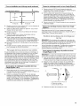
P e÷ e Upp® Cabinet
Disconnect power to outlet.
Remove all contents from upper cabinet.
Place Upper Cabinet Template against the bottom of the
upper cabinet, and attach with tape or thumbtacks. Make sure
the template centerline aligns with the vertical centerline on
the rear wall.
The "rear wall" arrows must be against the rear wall so that the
holes cut into the upper cabinet align with the holes inthe top
of the microwave oven.
NOTES:
• If the upper cabinet has a frame around it, trim the template
edges so that it fits inside the frame, against the upper cabinet
bottom. The template has trim lines to use as guides.
4=
If the wall behind the microwave oven (as installed) has a
partial wall covering (for example, tile backsplash), be sure the
"Rear Wall" arrows align to the thickest part of the rear wall
(for example, the thickness of the tiles rather than the drywall).
Make sure the 10" (25.4 cm) dimension from the rear wall to
points "D" and "E" on the template is maintained.
O O
8

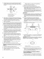
5. Cut the 11/2"(3.8 cm) diameter hole at the circular shaded area
"G" on the template. This hole is for the power supply cord.
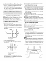
NOTE: Ifupper cabinet is metal, the supply cord bushing needs to
be installed around the supply cord hole, as shown.
B
A. Metal cabinet
B.Power supply cord bushing
6. Drill 3/8" (10 mm) holes at points "D" and "E" on the template.
These are for two 1/4-20 x 3" bolts and washers used to
secure the microwave oven to the upper cabinet.
For Roof Venting Installation Only
7. Cut 3/4" (19 mm) hole at one corner of the shaded rectangular
area "F" on Upper Cabinet Template.
8. Using a keyhole saw, cut out the rectangular area.
1.
2.
Domper Assembly
(for w_H ve_sH_g on_y)
Check that damper blade moves freely, and opens fully.
Position the damper assembly on the back of the microwave
oven so that the damper blade hinge is at the top, and the
damper blade opens away from the microwave oven.
A B C D
/
A. Back of microwave oven
B. Damper assembly
C. Damper blade
D. Sheet metal screws
3. Secure damper assembly with 2 sheet metal screws.
nstd the Mic ow e Oven
Excessive Weight Hazard
Use two or more people to move and install
microwave oven.
Failure to do so can result in back or other injury.
IMPORTANT: The control side of the microwave oven is the heavy
side. Handle the microwave oven gently.
1. Place a washer on each 1/4-20 x 3" flat-head bolt and place
inside upper cabinet near the 3/8" (10 mm) holes.
2. Make sure the microwave oven door is closed and taped shut.
!
3. Using 2 or more people, lift microwave oven and hang it on
support tabs at the bottom of mounting plate.
NOTE: To avoid damage to the microwave oven, do not grip or
use the door or door handle while the microwave oven is being
handled.
A. Mounting plate
B. Support tabs
B
4.
With front of microwave oven still tilted, thread power supply
cord through the power supply cord hole in the bottom of the
upper cabinet.
5. Rotate microwave oven up toward upper cabinet.
NOTE: If venting through the wall, make sure the damper
assembly fits easily into the vent in the wall cutout.
6. Push microwave oven against mounting plate and hold in
place.

NOTE:Ifmicrowaveovendoesnotneedtobeadjusted,skip
steps7-9.
7. Ifadjustmentisrequired,rotatemicrowaveovendownward.
Using2ormorepeople,liftmicrowaveovenoffofmounting
plate,andsetasideonacoveredsurface.
8. Loosenmountingplatescrews.Adjustmountingplateand
retightenscrews.
9. Repeatsteps3-6.
10.Withthemicrowaveovencentered,andwithatleastone
personholdingitinplace,insertboltsthroughuppercabinet
intomicrowaveoven.Tightenboltsuntilthereisnogap
betweenuppercabinetandmicrowaveoven.
NOTES:
• Someuppercabinetsmayrequireboltslongerorshorterthan
3"(7.6cm).Longerorshorterboltsareavailableatmost
hardwarestores.
Overtighteningboltsmaywarpthetopofthemicrowaveoven.
Toavoidwarping,woodfillerblocks(installertoprovide)
maybeadded.Theblocksmustbethesamethicknessas
thespacebetweentheuppercabinetbottomandthe
microwaveoven.
A
[
A. Bolts
For Roof Venting Installation Only
1. Insert damper assembly through the cabinet cutout so that the
long tab of the damper assembly slides under the raised tabs
of the damper plate. Then secure with sheet metal screw.
NOTE: The screw cannot be installed if the damper assembly is
not positioned as shown.
A B C
D E F
A. Raised tabs
B. Damper assembly
C. Sheet metal screw
D. Upper cabinet cutout
E. Long tab
E Damper plate
2. Connect vent to damper assembly.
A B
i i
R
A. Vent
B. Damper assembly (under vent)
Complete hstd ation
1. Install filters. Refer to the User Instructions for filter placement.
Electrical Shock Hazard
Plug into a grounded 3 prong outlet.
Do not remove ground prong.
Do not use an adapter.
Do not use an extension cord.
Failure to follow these instructions can result in death,
fire, or electrical shock.
2. Plug microwave oven into grounded 3 prong outlet.
3. Reconnect power.
4. Check the operation of microwave oven by placing 1 cup
(250 mL) of water on the turntable, and programming a cook
time of 1 minute at 100% power. Test vent fan and exhaust by
operating the vent fan.
5. If the microwave oven does not operate:
• Check that a household fuse has not blown, or that a
circuit breaker has not tripped. Replace the fuse or reset
the circuit breaker. If the problem continues, call an
electrician.
• Check that the power supply cord is plugged into a
grounded 3 prong outlet.
• See the User Instructions for troubleshooting information.
Installation is now complete.
Save Installation Instructions for future use.
10

VENTING DESIGNSPECIFICATIONS
This section is intended for architectural designer and
builder/contractor reference only.
NOTES:
• Vent materials needed for installation are not provided with
microwave hood combination.
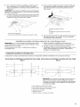
Rectangular to Round Transition
NOTE: The minimum 3" (7.6 cm) clearance must exist between
the top of the microwave oven and the rectangular to round
transition piece so that the damper can open freely and fully.
We do not recommend using a flexible metal vent.
Toavoid possible product damage, be sure to vent air outside,
unless using recirculation installation. Do not vent exhaust air
into concealed spaces, such as spaces within walls or
ceilings, attics, crawl spaces or garages.
For optimal venting installation, we recommend:
• using roof or wall caps that have back draft dampers
• using a rigid metal vent
• using the most direct route by minimizing the length of the
vent and number of elbows to provide efficient performance
• using uniformly sized vents
• using duct tape to seal all joints in the vent system
• using caulking compound to seal exterior wall or roof opening
around cap
• not installing 2 elbows together, for optimal hood performance
If venting through the wall, be sure that there is proper clearance
within the wall for the damper to open fully.
If venting through the roof, and rectangular to round transition is
used, be sure there is at least 3" (7.6 cm) of clearance between
the top of the microwave oven and the transition piece. See
"Rectangular to Round Transition" illustration.
B
C
E
A. Roof cap
B. 6" (15.2 cm) min. diameter round vent
C. Elbow (for wall venting only)
D. Wall cap
E. 3 ¼" x 10" to 6" (8.3 x 25.4 cm to 15.2 cm)
rectangular to round transition piece
F. Vent extension piece, at least 3" (7.6 cm) high
Recommended Standard Fittings
The following length equivalents are for use when figuring vent
length. See the examples in "Recommended Vent Length."
A B C
Roof venting Roof cap
Wall venting Wall cap
D E F G
A. Rectangular to round transition piece: 3 ¼" x 10" to 6" = 5 ft
(8.3 x 25.4 cm to 15.2 cm = 1.5 m)
B. Roof cap: 3 ¼" x 10" = 24 ft (8.3 x 25.4 cm = 7.3 m)
C. 90 °elbow: 3¼" x 10" = 25 ft (8.3 x 25.4 cm = 7.6 m)
D. 90 °elbow: 6" = 10 ft (15.2 cm = 3 m)
E. Wall cap: 3 ¼" x 10" = 40 ft (8.3 x 25.4 cm = 12.2 m)
F. 45 ° elbow: 6" = 5 ft (15.2 cm = 1.5 m)
G. 90 ° flat elbow: 3 ¼" x 10" = 10 ft (8.3 x 25.4 cm = 3 m)
11

Recommended Vent Length
A 31/4'' x 10" (8.3 x 25.4 cm) rectangular or 6" (15.2 cm) round vent
should be used.
The total length of the vent system including straight vent,
elbow(s), transitions and wall or roof caps must not exceed the
equivalent of 140 ft (42.7 m) for either type of vent. See
"Recommended Standard Fittings" section for equivalent lengths.
For best performance, use no more than three 90° elbows.
Tocalculate the length of the system you need, add the equivalent
lengths of each vent piece used in the system. See the following
examples:
31/4'' x 10" (8.3 x 25.4 cm) vent system = 73 ft (22.2 m) total
A
I_ 6ff (1.8m)
(0.6 m)
C
B
A. One 3 ¼" x 10" (8.3 x 25.4 cm) 90° elbow = 25 ft (7.6 m)
B. 1 waft cap = 40 ft (12.2 m)
C. 2 ft (0.6 m) + 6 ft (1.8 m) straight = 8 ft (2.4 m)
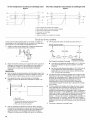
6" (15.2 cm) vent system = 73 ft (22.2 m) total
A B
_( 6 ft (1.8 m} }_1 :
%
................................................T_
2ft t .........................................................................................................
..........(0.6 m_
C D
A. Two 90° elbows = 20 ft (6.1 m)
B. 1 wall cap = 40 ft (12.2 m)
C. 1 rectangular to round transition piece = 5 ft (1.5 m)
D. 2 ft (0.6 m) + 6 ft (1.8 m) straight = 8 ft (2.4 m)
If the existing vent is round, a rectangular to round transition piece
must be used. In addition, a rectangular 3" (7.6 cm) extension vent
between the damper assembly and rectangular to round transition
piece must be installed to keep the damper from sticking.
ASSISTANCE
Call your authorized dealer or service center. When you call, you
will need the microwave oven model number and serial number.
Both numbers can be found on the model and serial number
plate, which is located behind the microwave oven door on the
front frame of the microwave oven.
If you need additional assistance, call us at our toll free number or
visit our website listed in the User Guide.
R®p)ac®menf Po#s
If any of the installation hardware needs to be replaced, call us at
our toll free number listed in the User Instructions.
Following is a list of available replacement parts. You will need
your model number located on the front facing of the microwave
oven opening, behind the door.
• Damper Assembly
• Mounting Plate
• Upper Cabinet Template
• Mounting Screw Kit (includes parts A-G in "Parts Supplied" in
the "Tools and Parts" section)
Filler Panel Kits are available from your dealer to use when
installing this microwave oven in a 36" (91.4 cm) or 42" (106.7 cm)
wide opening. The filler panels come in pairs. Each panel is 3"
(7.6 cm) wide.
l
o11o
Filler Panel Kit Number 8171336 White
8171337 Black
8171338 Biscuit
8171339 Stainless Steel
99403 Almond
See your authorized dealer or service center for details.
12

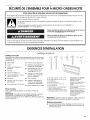
SECURITEDEL'ENSEMBLEFOURA MICRO-ONDES/HOTTE
Votre securite et celle des autres est tres importante.
Nous donnons de nombreux messages de s6curit6 importants dans ce manuel et sur votre appareil m6nager. Assurez-vous de
toujours lire tous les messages de s6curit6 et de vous y conformer.
Voici le symbole d'alerte de s6curit6.
Ce symbole d'alerte de s6curit6 vous signale les dangers potentiels de d6c_s et de blessures graves & vous
et & d'autres.
Tousles messages de s6curit6 suivront le symbole d'alerte de s6curit6 et le mot "DANGER" ou
"AVERTISSEMENT". Ces mots signifient •
Risque possible de d_cbs ou de blessure grave si vous ne
suivez pas imm_diatement les instructions.
Risque possible de d_cbs ou de blessure grave si vous
ne suivez pas les instructions.
Tousles messages de s6curit6 vous diront quel est le danger potentiel et vous disent comment r6duire le risque de blessure et
ce qui peut se produire en cas de non-respect des instructions.
EXIGENCESD'INSTALLATION
Outi)(®g®et pi@ces
Outillage n_cessaire ,
Rassembler les outils et pieces necessaires avant de commencer A
I'installation. Lire et suivre les instructions fournies avec les outils
mentionnes ici.
• Metre ruban •
• Crayon •
• Ruban de masquage ou
punaises •
• Ciseaux
• Tournevis Phillips n° 2
• Tournevis Phillips n° 3 (pour
vis de 1/4-20 x 3")
• Perceuse •
• M_ches de 3/16" (5 mm) et •
3/8" (10 mm)
• Scie-cloche de 3/4" (19 mm)
Pince a coupe diagonale
Detecteur magnetique (des
poteaux de colombage)
Cle & douille de 7/16" (ou
cle polygonale), pour vis
d'ancrage de 1/4" x 2"
Foret de 11/2"(3,8 cm) de
diam@tre pour placard de
bois ou metallique
Scie A guichet
Pistolet &calfeutrage et
compose de calfeutrage
resistant aux intemperies
• Ruban adhesif pour conduit
Pi_ces fournies
Pour la commande de pieces, voir la section "Pieces de
rechange".
REMARQUE : Les articles de quincaillerie present6s ci-dessous
sont destines & I'utilisation sur un colombage de bois. En
presence d'une structure de mur differente, utiliser les organes de
fixation appropries.
A. Visa t#te ronde de 1/4-20 x 3" (2)
B. Visa t#te plate de 1/4-20 x 3" (2)
C. Rondelles (2)
D. Ecrous articul#s (2)
E. Vis d'ancrage de 1/4" x 2" (2)
F. Vis de tSlerie (2)
G. Garniture pour trou de passage du
cordon d'alimentation (1)
H. Module de clapet anti-reflux (pour
d#charge atravers lemur ou le toit)
Composants non illustr#s :
Gabarit pour placard
sup#rieur (mural)
Plaque de montage (fixation
I'arriere du four a micro-
ondes)
Gabarit de carton (fait partie
de I'emballage)
Filtres a graisse en aluminium
Filtres a charbon (selon le
modele, les filtres a charbon
peuvent ne pas #tre inclus.
Voir les Instructions
d'utilisation.)
REMARQUE • Selon le modele de I'appareil, le filtre & graisse en
aluminium et le filtre & charbon peuvent _tre combines.
Mat_riaux n6cessaires
• Composants standard pour decharge a travers lemur ou &
travers le toit. Voir la section "Specifications/conception du
circuit d'evacuation".
13

D@pos÷du g®b®dt de o®don
Le moroeau de carton du dessus de I'emballage du four _ micro-
ondes est perfor& La partie a I'int@rieurdes trous de perforation
est _ utiliser comme gabarit de mur arri@re.
1. D@couper le long des trous perfor@s pour d@tacher le gabarit
du reste de I'emballage de carton.
2. Mettre le gabarit de carton de c6t@et s'y r@f@rerIors de I'@tape
d'installation "Trace sur lemur arriere".
Inspecter I'espace oQ le four a micro-ondes sera install&
L'emplacement d'installation doit disposer de :
• Dimensions minimales a respecter Iors de I'installation. Voir
I'illustration "Dimensions a respecter Iors de I'installation".
Au moins un poteau de colombage en bois 2" x 4"
(50,8 x 101,6 mm), et parement de pl&tre ou panneau de
gypse d'epaisseur 3/8" (10 mm) ou plus, dans I'ouverture du
placard.
• Capacite de support de charge de 150 Ib (68 kg), ceci incluant
le four & micro-ondes et les articles places a I'interieur du four
micro-ondes et du placard superieur.
• Prise de courant electrique reliee a la terre a I'interieur du
placard superieur. Voir la section "Specifications electriques".
REMARQUES :
Dans le cas de I'installation du four a micro-ondes a proximite
d'une paroi laterale sur le c6te gauche, veiller a laisser un
espace libre de 6" (15,2 cm) ou plus entre lemur et le four
micro-ondes, pour permettre la manceuvre d'ouverture
complete de la porte.
Les materiaux de certains placards et certains materiaux de
construction ne sont pas congus pour resister & la chaleur
emise par le four a micro-ondes Iors des operations de
cuisson. Consulter leconstructeur de la maison ou le fabricant
des placards pour determiner si les materiaux utilises
pourraient subir un changement de couleur, une
destratification ou d'autres dommages.
Exigences sp_ciales
Pour une installation avec d_charge murale seulement :
• L'ouverture decoupee doit _tre exempte d'obstruction pour
I'ajustement adequat du conduit, et pour que le clapet anti-
reflux puisse manceuvrer completement et librement.
Pour une installation avec d_charge & I'ext_rieur & travers
le toit seulement :
• Si I'on utilise un raccord de transition rectangulaire/rond, on
doit disposer d'un espace libre de 3" (7,6 cm) au-dessus du
four a micro-ondes pour que la lame du clapet anti-reflux
puisse manceuvrer completement et librement. Voir
I'illustration "Raccord de transition rectangulaire/rond" a la
section "Specifications/conception du circuit d'evacuation".
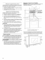
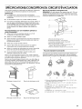
Dimensions _ respecter Iors de I'installation
REMARQUE : La prise de courant &3 alveoles reliee a la terre doit
_tre situ6e & I'interieur du placard superieur. Voir la section
"Specifications electriques".
A B
12" (30,5 cm) rain.
14" (35,6 cm) max.
profondeur du
placard sup_rieur et
du placard Jat_raJ
A. Poteau du colombage mural de 2" x 4"
B. Prise a 3 alv#oles refi#e a la terre
*30" (76,2 cm) est typique pour une hauteur d'installation de 66"
(167,6 cm). Les dimensions exactes peuvent varier en fonction
du type de cuisiniere/table de cuisson se trouvant en-dessous.
Dimensions du p oduit
14

Risque de choc _lectrique
Brancher sur une prise a 3 aIv_oles reli_e a la terre.
Ne pas eniever la broche de liaison a la terre.
Ne pas utiliser un adaptateur.
Ne pas utiiiser un cable de rallonge.
Le non=respect de ces instructions peut causer
un d_c_s, un incendie ou un choc _lectrique.
Observer les dispositions de tousles codes et reglements en
vigueur.
N_cessaire :
• Une alimentation electrique de 120 volts, 60 Hz, CA
seulement, 15 ou 20 amperes, protegee par un fusible ou un
disjoncteur.
Recommand_ :
• Un fusible temporise ou un disjoncteur temporis&
• Un circuit distinct exclusif & ce four a micro-ondes.
INSTRUCTIONS DE LIAISON
A LA TERRE
[]
Pour tout appareil m_nager connect_ par un cordon
de courant _lectrique :
IIfaut que le four & micro-ondes soit reli_ & la terre. En
cas de court-circuit _lectrique, la liaison & la terre r_duit le
risque de choc _lectrique car le courant _lectrique
dispose d'un itin@aire direct d'acheminement &la terre.
Le four & micro-ondes est dot_ d'un cordon de courant
_lectrique qui comporte un fil de liaison & la terre, avec
broche de liaison & la terre. On doit brancher la fiche sur
une prise de courant convenablement install_e et reli_e &
la terre.
AVERTISSEMENT : L'utilisation incorrecte du
dispositif de liaison &la terre peut susciter un risque de choc
_lectrique. L'utilisateur qui ne comprend pas bien les
instructions de liaison & la terre, ou qui n'est pas certain que
le four & micro-ondes soit convenablement reli_ & la terre,
devrait consulter un _lectricien ou un technicien qualifi&
Ne pas utiliser un c&ble de rallonge. Si le cordon de
courant _lectrique est trop court, demander & un _lectricien
ou un technicien qualifi_ d'installer une prise de courant &
proximit_ du four & micro-ondes.
CONSERVEZ CES
INSTRUCTIONS
INSTRUCTIONSD'INSTALLATION
D@pose de p Gq ae de montage
Selon votre modele, la plaque de montage peut se trouver soit
dans I'emballage en mousse, soit fixee a I'arriere du four
micro-ondes.
REMARQUE : Couvrir la surface de travail pour eviter de
I'endommager.
1. Retirer de la cavite du four a micro-ondes tous les articles qui
peuvent s'y trouver.
2. Si la plaque de montage est fixee sur la partie arriere du four &
micro-ondes, la retirer et la mettre de c6t&
3. Utiliser du ruban adhesif pour immobiliser la porte fermee du
four & micro-ondes afin qu'elle ne puisse pas s'ouvrir durant la
manipulation du four.
REMARQUE : Pour eviter d'endommager le four & micro-ondes,
ne pas prendre prise sur la porte ou la poignee de la porte durant
la manipulation du four a micro-ondes.
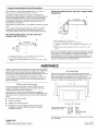
R dentation du moteu du venti ateu
Le four µ-ondes a ete configure &I'usine pour une
installation avec recyclage de I'air. Pour la decharge de I'air aspire
&travers lemur ou &travers le toit, on doit modifier le systeme de
ventilation du four.
REMARQUE : Si leproduit est destine & _tre utilise avec recyclage
de I'air, ne pas tenir compte de cette section. Conserver le module
du clapet pour le cas oQune autre methode d'evacuation serait
utilisee ulterieurement ou dans le cas oQle four µ-ondes
serait reinstalle ulterieurement en un autre endroit, avec decharge
&I'exterieur a travers le mur ou & travers le toit.
Pour une installation avec d_charge murale seulement
1.
0ter les vis fixant la plaque de support du clapet anti-reflux &
la partie superieure de I'exterieur du four µ-ondes. Faire
glisser la plaque de support du clapet anti-reflux vers I'avant
du four a micro-ondes et la soulever.
-4
2.
A. Vis
B.Plaque de support du clapetanti-reflux
Conserver ensemble la plaque de support du clapet et les vis;
les mettre de c6t&
15

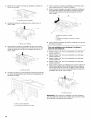
3=
4=
Retirer les 2 vis fixant le moteur du ventilateur a I'arriere du
four a micro-ondes.
A
A. Vis(dansles trousd#cal#s)
Soulever le moteur du ventilateur pour le sortir du four
micro-ondes.
7=
8.
Fixer & nouveau le moteur du ventilateur & I'arriere du four &
micro-ondes avec les 2 vis 6tees & I'etape 3.
Fixer & nouveau la plaque de support du clapet. Verifier que
les onglets de la plaque de support du clapet sont inser6s
dans les fentes situ6es sur la partie superieure du four &
micro-ondes.
A B
5=
A. Moteur du ventilateur
Faire pivoter le moteur du ventilateur de 180° pour que les
orifices de sortie soient alignes avec I'arriere du four µ-
ondes, et rabaisser le moteur du ventilateur dans le four
micro-ondes.
A
A. Orifice de sortie
6. A I'aide d'une pince & coupe diagonale, decouper doucement
au niveau des perforations des couvercles rectangulaires de
fermeture du clapet.
D
A. Plaque de support du clapet
B. Vis
C. Onglets de la plaque de support du clapet
D. Fentes
9. Fixer la plaque de support du clapet & I'aide des 2 vis qui ont
et6 retirees & I'etape 1.
Pour une installation avec d_charge & I'ext_rieur
travers le toit seulement
1=
2.
3.
4.
5.
Rep6ter I'etape 1 de "Pour une installation avec decharge
murale seulement".
Rep6ter I'etape 2 de "Pour une installation avec decharge
murale seulement".
Rep6ter I'etape 3 de "Pour une installation avec decharge
murale seulement".
Rep6ter I'etape 4 de "Pour une installation avec decharge
murale seulement".
Faire pivoter le moteur du ventilateur pour que les orifices de
sortie soient orientes vers le haut du four & micro-ondes, et
que les c6tes plats du moteur du ventilateur soient orientes
vers I'arriere du four & micro-ondes. Rabaisser le moteur du
ventilateur dans le four a micro-ondes.
A. Orifice de sortie
IMPORTANT : Si le moteur du ventilateur n'est pas positionne
avec les c6tes plats orientes vers I'arriere du four a micro-ondes
(tel qu'illustre), le rendement sera mediocre.
16

6= Fixer &nouveau le moteur du ventilateur & I'arriere du four &
micro-ondes avec les 2 vis 6tees &I'etape 3 de la section
"Pour une installation avec decharge murale seulement". Bien
serrer les vis.
REMARQUE • Si le moteur du ventilateur n'est pas correctement
oriente, les 2 vis 6tees & I'etape 3 ne peuvent pas etre reinstallees
sur le four a micro-ondes.
7. A I'aide d'une pince & coupe diagonale, decouper doucement
au niveau des perforations des couvercles rectangulaires sur
la plaque de support du clapet 6tee & I'etape 1.
8=
Fixer & nouveau la plaque de support du clapet. Verifier que
les onglets de la plaque de support du clapet sont inseres
dans les fentes situees sur la partie superieure du four
micro-ondes.
A B
I
D
A. Plaque de support du clapet
\ B. Vis
A B C. Onglets de la plaque de support du clapet
A. Pince a coupe diagonale D. Fentes
B. Couvercles rectangulaires de la plaque de support du clapet
g=
Fixer la plaque de support du clapet a I'aide des 2 vis qui ont
ete retirees & I'etape 1de la section "Pour une installation
avec decharge murale seulement".
dentifie position du/des p@®®u(x) du co ombag@
RI:MAROUI: : 8'il n'y a aucun poteau du colombage mural dans 1. Utiliser un detecteur magnetique pour Iocaliser dans
la zone delimitee par I'ouverture dans le placard superieur, ne pas I'ouverture les rives du/des poteau(x) du colombage mural.
installer le four & micro-ondes. 2. Marquer la position du centre de chaque poteau du
Voir les illustrations a la section "Configurations possibles du colombage, et tracer I'axe de chaque poteau & I'aide d'un fil
colombage mural"• plomb. Voir les illustrations a la section "Configurations
possibles du colombage mural"•
Configurations possibles du colombage mural
Les illustrations ci-dessous presentent des exemples de configurations preferees d'installation avec la plaque de montage•
Aucun poteau du colombage & la position des trous d'angle Aucun poteau du colombage & la position des trous d'angle
Figure 1 Figure2
B
'i
i
i
i
i
i
F
i
REMARQUE : Si le poteau de colombage mural se trouve & 6"
(15,2 cm) ou moins de I'axe central vertical (voir la section
"Trace sur lemur arriere"), seule une installation sans decharge
& I'exterieur (recyclage) ou une installation avec decharge par
le toit peut etre realisee.
A. Trous d'angle (sur la plaque de montage)
B.Axe vertical central de I'ouverture dans le placard
C• Axes centraux de poteau du colombage
D. Trous pour vis d'ancrage
E. Pattes de support
F. Reperes centraux sur la plaque de montage
17

Un trou d'angle face &un poteau du colombage mural
Figure3
Deux trous d'angle face &des poteaux du colombage mural
Figure4
S _
F !il
A. Trous d'angle (sur la plaque de montage)
B.Axe vertical central de I'ouverture clans le placard
C. Axes centraux de poteau du colombage
D. Trous pour vis d'ancrage
E. Pattes de support
F. Reperes centraux sur la plaque de montage
T ao@ a d@÷
Le four µ-ondes dolt _tre fixe sur au moins un poteau du
colombage mural, et de pref6rence sur 2 poteaux; on utilise pour
cela au moins 1 vis d'ancrage, et de pref6rence 2 vis.
1. Utiliser un metre ruban; determiner et marquer clairement la
position de I'axe central vertical de I'ouverture.
A. Axe central
2. Aligner les reperes centraux sur legabarit de carton (couvercle
superieur du carton) avec I'axe central sur lemur; veiller au
bon aplomb, et veiller ace que le sommet du gabarit de
carton soit en contact avec le bord inferieur du placard
superieur.
REMARQUES :
• Si la rive avant du placard superieur est plus basse que la rive
arriere, abaisser le gabarit de carton de maniere & ce que son
sommet soit au m_me niveau que la rive avant du placard.
• Si le gabarit de carton est endommage ou inutilisable,
mesurer et inscrire les dimensions indiquees a I'etape 4 sur
lemur.
A
................ • U ...........................D
C
B
A. Mur arriere
B. Gabarit de carton
C. Le sommet du gabarit de carton dolt #tre
align# avec la rive avant du placard.
D. Rive avant du placard sup#rieur
4. Oter le gabarit de carton et verifier les points de trace •
Fond du placardsup_ieur
t ' t
m
i
i
i
15a/4''
Axe central 17%"
(40,0 crn) i (43,8 crn)
i
141/8'' i 141/a''
,//L_I .............................. L............................ !...... ! .........
i Partie inf6rieure de
/
Trou d'angle de la plaque de' montage la plaque de montage
• L'axe de la rive inferieure doit _tre situe & 171/4"(43,8 cm)
de la partie inferieure du placard superieur et doit _tre
d'aplomb.
Les trous d'angle doivent _tre situes &153/4"(40,0 cm) de
la rive inferieure du placard superieur et doivent _tre
alignes les uns avec les autres. Chacun doit _tre situe
141/8'' (35,9 cm) de I'axe central.
5. Une fois les brides de support orientees vers I'avant (voir les
illustrations de la section "Identification de la position du/des
poteau(x) du colombage mural"), aligner le trace du centre de
la plaque de montage avec I'axe central sur lemur, en
s'assurant que sa rive inferieure est alignee avec I'axe
horizontal trace & I'etape 3 et que les trous d'angle sont
correctement indiques. S'assurer que la plaque de montage
est d'aplomb.
6. Tout en maintenant la plaque de montage en place, trouver
I'axe central/les axes centraux des poteaux du colombage
marque(s) a I'etape 2 de la section "Identification de la
position du/des poteau(x) du colombage mural", et marquer la
position d'au moins 1, et de preference 2, trou(s) a travers la
plaque de montage - le plus pres possible de I'axe central/des
axes centraux de chaque poteau du colombage. Voir les
figures 1,2 et/ou 3 de la section "Configurations possibles du
colombage mural" &la section "Identification de la position
du/des poteau(x) du colombage mural". Les trous &utiliser de
preference sont ceux qui sont marques en noir dans les zones
grisees.
7. Conserver la plaque de montage a part.
3.
Tout en maintenant le gabarit de carton en place, marquer
I'emplacement des deux trous situes dans les coins inferieurs
et tracer un axe horizontal en travers de la rive inferieure du
gabarit de carton. Ces marquages representent les trous
d'angle de la plaque de montage ainsi que la rive inferieure.
18

Pour une installation avec d_charge murale seulement
Fond du placard sup_rieur
I t Axe !entraJ
4" (10,2 crn)
6" (15,2 cm) 6" (15,2 cm)
_%" (1cm)
f
8. Marquer un point sur I'axe central a3/8" (1 cm) au-dessous de
la rive inferieure du placard superieur.
9. Utiliser un metre ruban; marquer un point &6" (15,2 cm) de
chaque c6te de I'axe central.
10. Marquer un point & 4" (10,2 cm) au-dessous de la marque
tracee & I'etape 8.
11. Utiliser une regle; tracer 2 lignes horizontales entre les
marques tracees aux etapes 8 et 10.
12. Tracer 2 lignes verticales & partir des marques faites &
I'etape 9 &I'aide d'un fil &plomb pour obtenir un rectangle
complet de 12" x 4" (30,5 x 10,2 cm). Ce rectangle delimite la
zone &decouper pour le passage du conduit d'evacuation.
13. Decouper un trou de 3/4" (19 mm) dans un coin de la zone &
decouper.
14. A I'aide d'une scie &guichet, decouper la zone & decouper
pour le passage du conduit d'evacuation.
Pe gage de ffous darts tour a i@e
En plus de la fixation sur au mains un poteau du colombage, on
doit egalement fixer la plaque de montage sur lemur au niveau
des deux trous d'angle. Si la position des trous d'angle ne
co'incide pas avec celle des poteaux du colombage mural, utiliser
deux visa t@teronde de 1/4-20 x 3" avec ecrou articule; s'il y a un
trou d'angle en cdfncidence avec le poteau de colombage, utiliser
une vis d'ancrage et une vis &t_te ronde de 1/4-20 x 3" avec
ecrou articule; si les deux trous co'fncident avec les poteaux de
colombage mural, utiliser deux vis d'ancrage. On presente ci-
dessous 3 configurations d'installation.
Aucun poteau du colombage & la position des trous
d'angle (Figures 1 et 2)
1.
2.
Percer des trous de 3/4" (19 mm) a travers lemur
I'emplacement des deux trous d'angle marques a I'etape 3 de
la section "Trace sur lemur arriere".
Percer un ou plusieurs trous de 3/16" (5 mm) dans le(s)
poteau(x) de colombage mural & I'emplacement du/des trou(s)
d'angle marque(s) a I'etape 6 de la section "Trace sur lemur
arriere". Voir les figures 1 et 2 du paragraphe "Configurations
possibles du colombage mural" & la section "Identification de
la position du/des poteau(x) du colombage mural".
Poteau du colombage mural & un trou d'angle (Figure 3)
1. Percer un trou de 3/16" (5 mm) & travers le poteau de
colombage mural a I'emplacement du trou d'angle marque
I'etape 3 dans "Trace sur lemur arriere".
2. Si I'on souhaite fixer I'appareil sur un second poteau du
colombage mural, percer un trou de 3/16" (5 mm) dans le
poteau du colombage mural a I'emplacement de I'autre trou
marque & I'etape 6 dans "Trace sur lemur arriere". Voir la
figure 3 dans le paragraphe "Configurations possibles du
colombage mural" &la section "Identification de la position
du/des poteau(x) du colombage mural".
3. Percer un trou de 3/4" (19 mm) & travers lemur au niveau de
I'autre trou d'angle.
Poteaux du colombage mural aux deux trous d'angle
(Figure 4)
Percer des trous de 3/16" (5 mm) a travers les poteaux du
colombage mural a I'emplacement des trous d'angle marques
I'etape 3 dans "Trace sur le mur arriere".
Fixation de p aque de montage
REMARQUE : Fixer la plaque de montage sur lemur, dans les
deux trous d'angle perces dans les poteaux du colombage et/ou
&travers le panneau de gypse & I'aide de vis & t_te ronde de 1/4-
20 x 3" avec ecrou articule ou vis d'ancrage de 1/4 x 2".
Voir les illustrations du paragraphe "Configurations possibles du
colombage mural" & la section "Identification de la position
du/des poteau(x) du colombage mural".
Aucun poteau du colombage & la position des trous
d'angle (Figures 1 et 2)
REMARQUE : La plaque de montage doit _tre fixee sur le mur et
sur au moins un poteau de colombage, ainsi qu'aux deux angles.
1. Alors que les pattes de support de la plaque de montage sont
orientees vers I'avant, inserer des vis & t_te ronde de 1/4-20 x
3" dans les deux trous d'angle de la plaque de montage.
2. Engager un ecrou articule sur chaque vis par I'arriere de la
plaque de montage. Veiller & disposer de suffisamment
d'espace pour que les ecrous articules puissent traverser le
panneau de gypse et se deployer a I'interieur de la cavite
murale.
,e
A. Visa t#te ronde de 1/4-20 x 3"
B. Plaque de montage
C. Ecrou articul# a ressort
3. Positionner la plaque de montage sur lemur.
19

4.
Pousser les deux vis avec ecrou articule a travers le panneau
de gypse; visser les vis & la main pour verifier que chaque
ecrou articule s'est deploy6 et prend appui contre le panneau
de gypse.
/ / \,_
// J\ \x .-,
/ / = \ \\\ L,
//
/ ...............................................................................................................................D
//
A. Visa t#te ronde de 1/4-20 x 3"
B. Plaque de montage
C. Ecrou articul# a ressort
D. Panneau de gypse
5. Inserer la/les vis d'ancrage dans le/les trou(s) perce(s) dans
le(s) poteau(x) de colombage mural a I'etape 2 du paragraphe
"Aucun poteau du colombage & la position des trous d'angle"
de la section "Pergage des trous dans le mur arriere".
6. Contr61er I'alignement de la plaque de montage; veiller
etablir un bon aplomb.
7. Serrer solidement toutes les pieces d'ancrage (vis et boulons).
Poteau du colombage mural & un trou d'angle (Figure 3)
1. Alors que les pattes de support de la plaque de montage sont
orientees vers I'avant, inserer une visa tete ronde de 1/4-20 x
3" dans le trou d'angle cdfncidant avec le trou de 3/4" (19 mm)
perce & I'etape 3 du paragraphe "Poteau du colombage mural
&un trou d'angle" de la section "Pergage des trous dans le
mur arriere".
2. Engager un ecrou articule sur la vis par I'arriere de la plaque
de montage. Veiller & disposer de suffisamment d'espace
pour que I'ecrou articule puisse traverser le panneau de gypse
et se deployer & I'interieur de la cavite murale.
3. Positionner la plaque de montage sur lemur.
4. Pousser la vis avec ecrou articule & travers le panneau de
gypse; visser la visa la main pour verifier que chaque ecrou
articule s'est deploye et prend appui contre le panneau de
gypse.
5. Inserer une vis d'ancrage dans le trou d'angle restant.
6. Si I'on souhaite fixer egalement I'appareil sur un second
poteau du colombage mural, inserer une vis d'ancrage dans
I'autre trou perce & I'etape 2 du paragraphe "Poteau du
colombage mural a un trou d'angle" de la section "Pergage
des trous dans lemur arriere".
7. Contr61er I'alignement de la plaque de montage; veiller
etablir un bon aplomb.
8. Serrer solidement la/les vis d'ancrage et le boulon.
Poteaux du colombage mural aux deux trous d'angle
(Figure 4)
1. Positionner la plaque de montage sur lemur.
2. Inserer les vis d'ancrage dans les deux trous d'angle.
3. Contr61er I'alignement de la plaque de montage; veiller
etablir un bon aplomb.
4. Serrer solidement les vis d'ancrage.
1.
2.
3.
Pr@pa ation du p ®card sup@ieu
Interrompre I'alimentation electrique.
Retirer tout le contenu du placard superieur.
Placer le gabarit du placard superieur contre le fond du
placard superieur, et le fixer avec du ruban adhesif ou des
punaises. Veiller & aligner I'axe central du gabarit avec I'axe
vertical central trace sur le mur arriere.
Les fleches correspondant au mur arriere doivent etre contre
lemur arriere, pour qu'on puisse obtenir I'alignement des
trous decoupes dans le placard superieur avec les trous situes
au sommet du four a micro-ondes.
REMARQUES :
4.
Si le placard superieur comporte un cadre perimetrique, tailler
les bords du gabarit de telle maniere qu'il puisse s'ajuster
dans le cadre, contre le fond du placard superieur. Le gabarit
comporte des lignes de decoupe qu'on peut utiliser comme
guides.
Si lemur situe derriere le micro-ondes comporte un
revetement mural partiel (par exemple, un dosseret &
carreaux), s'assurer que les fleches correspondant au mur
arriere s'alignent avec la partie la plus epaisse du mur arriere
(par exemple, I'epaisseur des carreaux plut6t que le panneau
de gypse).
Veiller & laisser un espace de 10" (25,4 cm) entre le mur arriere
et les points "D" et "E" sur le gabarit.
O O
O 10" O
5. Percer le trou de diametre 11/2'' (3,8 cm) dans la zone circulaire
grisee "G" du gabarit. Ce trou est utilise pour le passage du
cordon d'alimentation.
REMARQUE : Si le placard superieur est metallique, la bague de
cordon d'alimentation necessite d'etre installee autour du trou de
passage du cordon d'alimentation -voir I'illustration.
B
A. Placard m#tallique
B. Garniture du trou de passage du cordon d'alimentation
6.
Percer des trous de 3/8" (10 mm) aux points "D" et "E" du
gabarit. Ces trous sont utilises pour le passage de deux vis de
1/4-20 x 3" avec rondelle, utilisees pour la fixation du four
micro-ondes contre le placard superieur.
Pour une installation avec d_charge & I'ext_rieur
travers le toit seulement
7. Decouper un trou de 3/4" (19 mm) dans un coin de la zone
ombree rectangulaire "F" sur le gabarit du placard superieur.
8. A I'aide d'une scie a guichet, decouper la zone rectangulaire.
20
La page est en cours de chargement...
La page est en cours de chargement...
La page est en cours de chargement...
La page est en cours de chargement...
-
 1
1
-
 2
2
-
 3
3
-
 4
4
-
 5
5
-
 6
6
-
 7
7
-
 8
8
-
 9
9
-
 10
10
-
 11
11
-
 12
12
-
 13
13
-
 14
14
-
 15
15
-
 16
16
-
 17
17
-
 18
18
-
 19
19
-
 20
20
-
 21
21
-
 22
22
-
 23
23
-
 24
24


Maytag YMMV4205DW0 Installaion Instructions
- Taper
- Installaion Instructions
- Ce manuel convient également à
dans d''autres langues
- English: Maytag YMMV4205DW0
Autres documents
-
IKEA YMH1170XSS1 Guide d'installation
-
IKEA IMH172DS1 Guide d'installation
-
-
KitchenAid YKHMS2050SB0 Guide d'installation
-
KitchenAid YWML75011HW0 Guide d'installation
-
Inglis IRH32000 Guide d'installation
-
KitchenAid WML75011HB Guide d'installation
-
KitchenAid W11496339A Manuel utilisateur
-
Whirlpool YUMV4084BS Guide d'installation
-
Unbranded UMH50008HS Guide d'installation