GE DCCB330GJWC Guide d'installation
- Catégorie
- Sèche-linge électriques
- Taper
- Guide d'installation
Ce manuel convient également à

WARNING RISK OF FIRE
• To reduce the risk of severe injury or death, follow all installation
instructions.
&ORWKHVGU\HULQVWDOODWLRQPXVWEHSHUIRUPHGE\DTXDOL¿HGLQVWDOOHU
• Install the clothes dryer according to these instructions and in
accordance with local codes.
• California Safe Drinking Water and Toxic Enforcement Act
This act requires the governor of California to publish a list of
substances known to the state to cause cancer, birth defects or other
reproductive harm and requires businesses to warn customers of
potential exposure to such substances. Gas appliances can cause
minor exposure to four of these substances, namely benzene,
carbon monoxide, formaldehyde and soot, caused primarily by the
incomplete combustion of natural gas or LP fuels. Properly adjusted
dryers will minimize incomplete combustion. Exposure to these
substances can be minimized further by properly venting the dryer
to the outdoors.
• This dryer must be exhausted to the outdoors.
• Use only rigid metal 4” diameter ductwork inside the dryer cabinet
and use only UL approved transition ducting between the dryer and
the home duct.
'2127LQVWDOODFORWKHVGU\HUZLWKÀH[LEOHSODVWLFGXFWLQJ
PDWHULDOV,IÀH[LEOHPHWDOVHPLULJLGRUIRLOW\SHGXFWLVLQVWDOOHGLW
must be UL listed and installed in accordance with the instructions
found in “Connecting The Dryer To House Vent” on page 5 of this
manual. Flexible venting materials are known to collapse, be easily
FUXVKHGDQGWUDSOLQW7KHVHFRQGLWLRQVZLOOREVWUXFWGU\HUDLUÀRZ
DQGLQFUHDVHWKHULVNRI¿UH
• Do not install or store this appliance in any location where it could
be exposed to water and or weather.
• 6DYHWKHVHLQVWUXFWLRQV,QVWDOOHUV%HVXUHWROHDYHWKHVH
LQVWUXFWLRQVZLWKWKHFXVWRPHU
IN THE COMMONWEALTH OF MASSACHUSETTS
• This product must be installed by a licensed
SOXPEHURUJDV¿WWHU
• When using ball-type gas shut-off valves, they
VKDOOEHWKH7KDQGOHW\SH
• A flexible gas connector, when used, must not
H[FHHGIHHW
Installation
Instructions
Gas Dryer
02
4XHVWLRQV"&DOO*(&$5(6RUYLVLWRXU:HEVLWHDW*($SSOLDQFHVFRP
,Q&DQDGDFDOORUYLVLWZZZ*($SSOLDQFHVFD
BEFORE YOU BEGIN
Read these instructions completely and
FDUHIXOO\
• IMPORTANT- Save these instructions for
local inspector’s use.
• IMPORTANT- Observe all governing
codes and ordinances.
• Note to Installer - %H VXUH WR OHDYH WKHVH
instructions with the customer.
• Note to Customer - Keep these instructions with
your Owner’s Manual for future reference.
%HIRUHWKHROGGU\HULVUHPRYHGIURPVHUYLFHRU
discarded, remove the dryer door.
• Inspect the dryer exhaust outlet and straighten
the outlet walls if they are bent.
• Service information and the wiring diagram
are located in the control console.
• Do not allow children on or in the appliance.
Close supervision of children is necessary
when the appliance is used near children.
• Install the dryer where the temperature is
above 50°F for satisfactory operation of the
dryer control system.
• Product failure due to improper installation is
not covered under the Warranty.
234D2217P002 31-16736 10-13 GE
LEVEL
8" PIPE WRENCH
10" ADJUSTABLE WRENCHES
(x2)
TOOLS YOU WILL NEED
SLIP JOINT PLIERS
FLAT BLADE SCREWDRIVER
MATERIALS YOU WILL NEED
GLOVES
SAFETY
GLASSES
4" DUCT
CLAMPS (2)
OR
4" SPRING
CLAMPS (2)
EXHAUST
HOOD
4" DIA. METAL
ELBOW
4" DIA. FLEXIBLE METAL (SEMI-RIGID)
UL LISTED TRANSITION DUCT
(IF NEEDED)
KIT WX08X10077 (INCLUDES 2 ELBOWS)
4" DIA. METAL DUCT
(RECOMMENDED)
4" DIA. FLEXIBLE METAL (FOIL TYPE)
UL LISTED TRANSITION DUCT
(IF NEEDED.)
DUCT TAPE
SOAP SOLUTION
FOR LEAK DETECTION
PIPE
COMPOUND
FLEXIBLE GAS LINE CONNECTOR

Installation Instructions
2
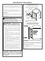
Minimum Clearance Other Than Alcove or Closet Installation
0LQLPXPFOHDUDQFHWRFRPEXVWLEOHVXUIDFHVDQGIRUDLURSHQLQJDUHLQFOHDUDQFHERWKVLGHVDQGLQUHDU
Consideration must be given to provide adequate clearance for installation and service.
1
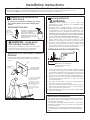
PREPARING FOR INSTALLATION
OF NEW DRYER
7,3,QVWDOO\RXUGU\HUEHIRUHLQVWDOOLQJ\RXUZDVKHU
This will allow better access when installing dryer
H[KDXVW
DISCONNECTING GAS
WARNING - NEVER REUSE
2/')/(;,%/(&211(&7256
7KHXVHRIROGÀH[LEOHFRQQHFWRUVFDQFDXVHOHDNV
DQGSHUVRQDOLQMXU\$OZD\VXVHQHZÀH[LEOH
connectors when installing gas appliances.
REMOVING LINT FROM WALL EXHAUST
OPENING
• Remove and discard existing plastic or metal foil
transition duct and replace with UL listed transition
duct.
INTERNAL DUCT
OPENING
CHECK THAT EXHAUST
HOOD DAMPER OPENS
AND CLOSES FREELY.
WALL
TILT THE DRYER SIDEWAYS
AND REMOVE THE FOAM
SHIPPING PADS BY
PULLING AT THE SIDES
AND BREAKING THEM
AWAY FROM THE DRYER
LEGS. BE SURE TO
REMOVE ALL OF THE
FOAM PIECES AROUND
THE LEGS.
TURN GAS
SHUT-OFF
VALVE TO THE
OFF POSITION.
DISCONNECT AND DISCARD OLD
FLEXIBLE GAS CONNECTOR AND
OLD DUCTING MATERIAL.
REPLACE WITH NEW CSA(AGA)
APPROVED FLEXIBLE GAS LINE
CONNECTOR AND UL APPROVED
TRANSITION DUCT.
2
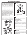
GAS REQUIREMENTS
WARNING
• Installation must conform to local codes and
ordinances,or in their absence, the NATIONAL FUEL
GAS CODE,ANSI Z223.
• 7KLV JDV GU\HU LV HTXLSSHG ZLWK D 9DOYH %XUQHU
Assembly for use only with natural gas. Using conversion
NLW :(; \RXU ORFDO VHUYLFH RUJDQL]DWLRQ FDQ
FRQYHUW WKLV GU\HU IRU XVH ZLWK SURSDQH /3 JDV $//
&219(56,216 0867 %( 0$'( %< 3523(5/< 75$,1('
AND QUALIFIED PERSONNEL AND IN ACCORDANCE WITH
LOCAL CODES AND ORDINANCE REQUIREMENTS.
• The dryer must be disconnected from the gas supply
piping system during any pressure testing of that
V\VWHPDWDWHVWSUHVVXUHLQH[FHVVRI36,.3D
• The dryer must be isolated from the gas supply piping
V\VWHPE\FORVLQJWKHHTXLSPHQWVKXWRȺYDOYHGXULQJ
any pressure testing of the gas supply piping of test
SUHVVXUHHTXDOWRRUOHVVWKDQ36,.3D
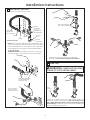
DRYER GAS SUPPLY CONNECTION
• $LQ1DWLRQDO3LSH7DSHUWKUHDGSOXJJHGWDSSLQJ
accessible for test gauge connection, must be installed
immediately upstream of the gas supply connection to
the dryer. Contact your local gas utility should you have
questions on the installation of the plugged tapping.
• 6XSSO\OLQHLVWREHLQULJLGSLSHDQGHTXLSSHGZLWK
DQDFFHVVLEOHVKXWRȺZLWKLQIWRIDQGLQWKHVDPH
room with the dryer.
• Use pipe thread sealer compound appropriate for
QDWXUDORU/3JDVRUXVH7HÀRQWDSH
• <RXPXVWXVHZLWKWKLVGU\HUDÀH[LEOHPHWDOFRQQHFWRU
OLVWHGFRQQHFWRU$16,=&6$7KHOHQJWKRI
the connect shall not exceed 3 ft.
• &RQQHFWÀH[LEOHPHWDOFRQQHFWRUWRGU\HUDQGJDVVXSSO\
• 2SHQVKXWRȺYDOYH
• Gas clothes dryers input ratings are based on sea level
operation and need not be adjusted for operation at or
below 2000 ft. elevation.
For operation at elevations above 2000 ft., input ratings
VKRXOGEHUHGXFHGDWDUDWHRISHUFHQWIRUHDFK
ft. above sea level.
• Installation must conform to local codes and ordinances
or, in their absence, the NATIONAL FUEL GAS CODE, ANSI
Z223.
ADJUSTING FOR ELEVATION
2"
2-5/8"
3/8" NPT MALE THREAD GAS SUPPLY
NOTE: Add to vertical dimension
the distance between cabinet
bottom to floor.

Installation Instructions
3
3
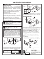
RECONNECTING GAS
NEW METAL
FLEXIBLE GAS
LINE CONNECTOR
ADAPTER
ELBOW
ITEMS NOT SUPPLIED
ADAPTER
SHUT-OFF
VALVE
PIPE SIZE
AT LEAST 1/2"
1/8" NPT PIPE
PLUG FOR
CHECKING GAS
INLET PRESSURE
3/8" NPT
Listed connector ANSI Z21.24 / CSA 6.10
FLARE
NPT
NOTE: 7KHFRQQHFWRUDQG¿WWLQJVDUHGHVLJQHGIRUXVH
only on the original installation and are not to be reused
IRUDQRWKHUDSSOLDQFHRUDWDQRWKHUORFDWLRQ.HHSÀDUH
end of adaptor free of grease, oil and thread sealant.
CAUTION: Use adaptors as shown. Connector
nuts must not be connected directly to pipe threads.
APPLY PIPE COMPOUND
TO THE ADAPTER AND
DRYER GAS INLET.
Tighten the flexible
gas line using two
adjustable wrenches.
APPLY PIPE COMPOUND
TO ALL MALE THREADS.
Tighten all connections using two adjustable
wrenches. Do not overtorque gas connections!
Check all connections for leaks with soapy solution or
equivalent. Apply soap solution. Leak test solution must
not contain ammonia which could cause damage to the
EUDVV¿WWLQJVIf leaks are found, close valve, retighten the
joint, and repeat the soap test.
LEAK TEST
WARNING - NEVER USE AN OPEN
)/$0(727(67)25*$6/($.6
OPEN
GAS VALVE.

EXHAUST INFORMATION
WARNING - IN CANADA AND IN
THE UNITED STATES, THE REQUIRED EXHAUST
'8&7 ',$0(7(5 ,6 LQ PP '2 127
USE DUCT LONGER THAN SPECIFIED IN THE
(;+$867/(1*7+7$%/(
8VLQJH[KDXVWORQJHUWKDQVSHFL¿HGOHQJWKZLOO
• Increase the drying times and the energy cost.
• Reduce the dryer life.
$FFXPXODWHOLQWFUHDWLQJDSRWHQWLDO¿UHKD]DUG
The correct exhaust installation is YOUR RESPONSIBILITY
Problems due to incorrect installation are not covered
E\WKHZDUUDQW\
Remove and discard existing plastic or metal foil
transition duct and replace with UL listed transition duct.
The MAXIMUM ALLOWABLE duct length and number of
bends of the exhaust system depends upon the type of
GXFW QXPEHU RI WXUQV WKH W\SH RI H[KDXVW KRRG ZDOO
FDSDQGDOOFRQGLWLRQVQRWHGEHORZ7KHPD[LPXPGXFW
length for rigid metal duct is shown in the table below.
4" DIA.
4"
4" DIA.
4" DIA.
2-1/2"
RECOMMENDED MAXIMUM LENGTH
Exhaust Hood Types
Recommended
No. of 90°
Elbows
Rigid
Metal
Rigid
Metal
90 Feet
60 Feet
45 Feet
35 Feet
25 Feet
60 Feet
45 Feet
35 Feet
25 Feet
15 Feet
0
1
2
3
4
Use only for short
run installations
EXHAUST LENGTH
ELECTRICAL CONNECTION
INFORMATION
WARNING - TO REDUCE THE
RISK OF FIRE, ELECTRICAL SHOCK,
AND PERSONAL INJURY:
• DO NOT USE AN EXTENSION CORD
OR AN ADAPTER PLUG WITH THIS
$33/,$1&(
Dryer must be electrically grounded in accordance
with local codes and ordinances, or in the absence
of local codes, in accordance with the NATIONAL
(/(&75,&$/&2'($16,1)3$12
ELECTRICAL REQUIREMENTS
7KLVDSSOLDQFHPXVWEHVXSSOLHGZLWK9+]DQG
connected to a properly grounded branch circuit,
SURWHFWHGE\DRUDPSFLUFXLWEUHDNHURUWLPH
GHOD\IXVH,IHOHFWULFDOVXSSO\SURYLGHGGRHVQRWPHHW
WKH DERYH VSHFL¿FDWLRQV LW LV UHFRPPHQGHG WKDW D
OLFHQVHGHOHFWULFLDQLQVWDOODQDSSURYHGRXWOHW
WARNING - THIS DRYER IS
EQUIPPED WITH A THREE-PRONG
*5281',1* 3/8* )25 <285
PROTECTION AGAINST SHOCK HA ZARD
AND SHOULD BE PLUGGED DIRECTLY
INTO A PROPERLY GROUNDED THREE-
3521*5(&(37$&/('2127&8725
REMOVE THE GROUNDING PRONG
)5207+,63/8*
LOCAL CODES PERMIT,
N
EXTERNAL GROUND WIRE
OT PROVIDED), WHICH MEETS
O
CAL CODES, MAY BE ADDED
Y
ATTACHING TO THE GREEN
R
OUND SCREW ON THE REAR
F
THE DRYER, AND TO A GROUNDED
E
TAL COLD WATER PIPE OR OTHER
S
TABLISHED GROUND.
ENSURE PROPER GROUND EXISTS BEFORE USE
• For every extra 90° elbow, reduce the allowable vent system
OHQJWKE\IW
• Two 45° elbows will be treated like one 90° elbow.
• For the side exhaust installations, add one 90° elbow to the
chart.
• The total vent system length includes all the straight
SRUWLRQVDQGHOERZVRIWKHV\VWHPWUDQVLWLRQGXFWLQFOXGHG
EXHAUST SYSTEM CHECK LIST
HOOD OR WALL CAP
• Terminate in a manner to prevent back drafts or entry of
birds or other wildlife.
• Termination should present minimal resistance to the
H[KDXVWDLUÀRZDQGVKRXOGUHTXLUHOLWWOHRUQRPDLQWHQDQFH
to prevent clogging.
• Never install a screen in or over the exhaust duct. This
could cause lint build up.
:DOOFDSVPXVWEHLQVWDOOHGDWOHDVWLQDERYHJURXQG
level or any other obstruction with the opening pointed
down.
SEPARATION OF TURNS
For best performance, separate all turns by at least 4 ft. of
straight duct, including distance between last turn and
exhaust hood.
TURNS OTHER THAN 90º
• One turn of 45º or less may be ignored.
• Two 45º turns should be treated as one 90º turn.
• Each turn over 45º should be treated as one 90º turn.
Installation Instructions
4

SEALING OF JOINTS
• All joints should be tight to avoid leaks. The male end of
each section of duct must point away from the dryer.
• The duct shall not be assembled with screws or other
fastening means that extend into the duct and catch
lint.
'XFW MRLQWV FDQ EH PDGH DLU DQG PRLVWXUHWLJKW E\
wrapping the overlapped joints with duct tape.
• Horizontal runs should slope down toward the outdoors
LQFKSHUIRRW
INSULATION
Duct work that runs through an unheated area or is near air
conditioning should be insulated to reduce condensation
DQGOLQWEXLOGXS
EXHAUST CONNECTION
BEFORE PERFORMING THIS EXHAUST
INSTALLATION, BE SURE TO DISCONNECT THE
'5<(5)520,76(/(&75,&$/6833/<
WARNING - TO REDUCE THE
RISK OF FIRE OR PERSONAL INJURY:
•
This clothes dryer must be exhausted to the outdoors.
• Use only 4” rigid metal ducting for the home exhaust
duct.
8VH RQO\ µ ULJLG PHWDO RU 8/OLVWHG ÀH[LEOH PHWDO
VHPLULJLG RU IRLOW\SH GXFW WR FRQQHFW WKH GU\HU
to the home exhaust duct. It must be installed
in accordance with the instructions found in
´&RQQHFWLQJWKH'U\HUWR+RXVH9HQWµRQSDJHV
of this manual.
• Do not terminate exhaust in a chimney, a wall,
a ceiling, gas vent, crawl space, attic, under an
HQFORVHG ÀRRU RU LQ DQ\ RWKHUFRQFHDOHG VSDFHRI
a building. The accumulated lint could create a
potential ¿UHKD]DUG
• Never terminate the exhaust into a common duct
with a kitchen exhaust system. A combination of
JUHDVHDQGOLQWFUHDWHVDSRWHQWLDO¿UHKD]DUG
'RQRWXVHGXFWORQJHUWKDQVSHFL¿HGLQWKHH[KDXVW
length table. Longer ducts can accumulate lint,
FUHDWLQJDSRWHQWLDO¿UHKD]DUG
• Never install a screen in or over the exhaust duct. This
ZLOOFDXVHOLQWWRDFFXPXODWHFUHDWLQJDSRWHQWLDO¿UH
hazard.
• Do not assemble ductwork with any fasteners
that extend into the duct. These fasteners can
DFFXPXODWHOLQWFUHDWLQJDSRWHQWLDO¿UHKD]DUG
• Do not obstruct incoming or exhausted air.
•
Provide an access for inspection and cleaning of the
exhaust system, especially at turns and joints. Exhaust
system shall be inspected and cleaned at least once a
year.
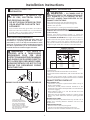
CONNECTING THE DRYER TO HOUSE VENT
RIGID METAL TRANSITION DUCT
• For best drying performance, a rigid metal transition duct
is recommended.
• Rigid metal transition ducts reduce the risk of crushing
and kinking.
GAS
INLET
PIPE
NOTE: WE STRONGLY RECOMMEND SOLID METAL EXHAUST DUCTING.
HOWEVER, IF FLEXIBLE DUCTING IS USED IT
NOT PLASTIC.
MUST BE UL-LISTED METAL
EXTERNAL
DUCT
OPENING
DUCT TAPE OR
DUCT CLAMP
DUCT TAPE OR
DUCT CLAMP
(CUT TO PROPER
LENGTH)
4" METAL DUCT
FOR STRAIGHT LINE INSTALLATION, CONNECT THE DRYER EXHAUST TO
THE EXTERNAL EXHAUST HOOD USING DUCT TAPE OR CLAMP.
CSA (AGA) APPROVED
NEW FLEXIBLE GAS
LINE CONNECTOR
STANDARD REAR EXHAUST
9HQWHGDWÀRRUOHYHO
STANDARD REAR EXHAUST
9HQWHGDERYHÀRRUOHYHO
NOTE: ELBOWS WILL PREVENT DUCT KINKING AND
&2//$36,1*
THIS DRYER COMES READY FOR REAR
(;+$867,1*,)63$&(,6/,0,7('86(7+(
INSTRUCTIONS IN STEP 13 TO EXHAUST
DIRECTLY FROM THE SIDE OR BOTTOM OF
7+(&$%,1(7
Installation Instructions
5

LEVELING DRYER
9
ALCOVE OR CLOSET INSTALLATION
• If your dryer is approved for installation in an alcove or
closet, it will be stated on a label on the dryer back.
• The dryer MUST be vented to the outdoors. See the
EXHAUST INFORMATIONVWHS
• Minimum clearance between dryer cabinet and
DGMDFHQWZDOOVRURWKHUVXUIDFHVLV
0 in. either side
3 in. front
3 in. rear
0LQLPXPYHUWLFDOVSDFHIURPÀRRUWRRYHUKHDGFDELQHWV
ceiling, etc. is 52 in.
• Closet doors must be louvered or otherwise ventilated
DQGPXVWFRQWDLQDPLQLPXPRIVTLQRIRSHQDUHD
equally distributed. If the closet contains both a washer
DQGDGU\HUGRRUVPXVWFRQWDLQDPLQLPXPRIVT
in. of open area equally distributed.
• The closet should be vented to the outdoors to prevent
gas pocketing in case of a gas leak in the supply line.
1RRWKHUIXHOEXUQLQJDSSOLDQFHVKDOOEHLQVWDOOHGLQWKH
same closet with the dryer.
ELBOWS HIGHLY
RECOMMENDED
ELBOW HIGHLY
RECOMMENDED
DO
DO NOT
CRUSH
FLEXIBLE
EXHAUST
AGAINST
WALL.
DO NOT
SIT DRYER
ON FLEXIBLE
EXHAUST.
DO NOT USE
EXCESSIVE
EXHAUST
LENGTH
DON’T
8
4 LEVELING LEGS
2 ANTI-TIP LEGS
STAND THE DRYER UPRIGHT NEAR THE
FINAL LOCATION AND ADJUST THE 4 LEVELING
LEGS TO MATCH THE HEIGHT OF YOUR WASHER.
ADJUST THE 2 ANTI-TIP LEGS TO CONTACT
THE FLOOR.
LEVEL
SIDE-TO-SIDE.
LEVEL
FRONT-TO-BACK.
8//,67(' )/(;,%/( 0(7$/ 6(0,5,*,' 75$16,7,21
DUCT
,IULJLGPHWDOGXFWFDQQRWEHXVHGWKHQ8/OLVWHGÀH[LEOH
PHWDOVHPLULJLGGXFWLQJFDQEHXVHG.LW:;;
1HYHULQVWDOOÀH[LEOHPHWDOGXFWLQZDOOVFHLOLQJVÀRRUVRU
other enclosed spaces.
•
7RWDO OHQJWK RI ÀH[LEOH PHWDO GXFW VKRXOG QRW H[FHHG IHHW
P
• For many applications, installing elbows at both the dryer
DQG WKH ZDOO LV KLJKO\ UHFRPPHQGHG VHH LOOXVWUDWLRQV
EHORZ (OERZV DOORZ WKH GU\HU WR VLW FORVH WR WKH ZDOO
without kinking and or crushing the transition duct,
maximizing drying performance.
• Avoid resting the duct on sharp objects.
8//,67(')/(;,%/(0(7$/)2,/7<3(75$16,7,21'8&7
• I
n special installations, it may be necessary to connect the
GU\HUWRWKHKRXVHYHQWXVLQJDÀH[LEOHPHWDOIRLOW\SHGXFW
$ 8/OLVWHG ÀH[LEOH PHWDO IRLOW\SH GXFW PD\ EH XVHG 21/<
LQLQVWDOODWLRQVZKHUHULJLGPHWDORUÀH[LEOHPHWDOVHPLULJLG
ducting cannot be used AND where a 4” diameter can be
maintained throughout the entire length of the transition duct.
•
,Q &DQDGD DQG WKH 8QLWHG 6WDWHV RQO\ WKH ÀH[LEOH PHWDO
IRLOW\SHGXFWVWKDWFRPSO\ZLWKWKH´2XWOLQHIRU&ORWKHV
'U\HU7UDQVLWLRQ'XFW6XEMHFW$µVKDOOEHXVHG
1HYHULQVWDOOÀH[LEOHPHWDOGXFWLQZDOOVFHLOLQJVÀRRUVRU
other enclosed spaces.
•
7RWDO OHQJWK RI ÀH[LEOH PHWDO GXFW VKRXOG QRW H[FHHG IHHW
P
• Avoid resting the duct on sharp objects.
)RUEHVWGU\LQJSHUIRUPDQFH
6OLGHRQHHQGRIWKHGXFWRYHUWKHFORWKHVGU\HURXWOHWSLSH
2. Secure the duct with a clamp.
3. With the dryer in its permanent position, extend the duct
to its full length. Allow 2” of duct to overlap the exhaust
SLSH &XW RȺ DQG UHPRYH H[FHVV GXFW .HHS WKH GXFW DV
VWUDLJKWDVSRVVLEOHIRUPD[LPXPDLUÀRZ
4. Secure the duct to the exhaust pipe with the other clamp.
10
BATHROOM OR BEDROOM
INSTALLATION
• The dryer MUST be vented to the outdoors. See EXHAUST
,1)250$7,21VWHS
• The installation must conform with local codes or, in the
absence of local codes, with the NATIONAL ELECTRICAL
&2'($16,1)3$12
Installation Instructions

13
DRYER EXHAUST TO LEFT OR
BOTTOM
WARNING - BEFORE PERFORMING
THIS EXHAUST INSTALLATION, BE SURE
TO DISCONNECT THE DRYER FROM ITS
(/(&75,&$/ 6833/< 3527(&7 <285
HANDS AND ARMS FROM SHARP EDGES
:+(1:25.,1*,16,'(7+(&$%,1(7
%(685(72:($5*/29(6
REMOVE
SCREW
AND SAVE.
REMOVE DESIRED
KNOCKOUT
(ONE ONLY).
Through the rear opening, locate the tab in the middle of
the appliance base. Lift the tab to about 45º using a flat
blade screwdriver.
BEND TAB
UP 45
o
LEFT SIDE
EXHAUST
PORTION "A"
FIXING
HOLE
MOBILE OR MANUFACTURED HOME
INSTALLATION
• Installation must conform to the MANUFACTURED
+20(&216758&7,216$)(7<67$1'$5'7,7/(
3$57RUZKHQVXFKVWDQGDUGLVQRWDSSOLFDEOH
ZLWK $0(5,&$1 1$7,21$/ 67$1'$5' )25 02%,/(
+20($16,1)3$12%
• The dryer MUST be vented to the outdoors with the
termination securely fastened to the mobile home
VWUXFWXUH6HH(;+$867,1)250$7,21VHFWLRQ
• The vent MUST NOT be terminated beneath a mobile or
manufactured home.
7KHYHQWGXFWPDWHULDO0867%(0(7$/
.,7 ' 0867 EH XVHG WR DWWDFK WKH GU\HU
securely to the structure.
• The vent MUST NOT be connected to any other duct,
vent, or chimney.
•
Do not use sheet metal screws or other fastening devices
which extend into the interior of the exhaust vent.
• Provide an opening with a free area of at least 25 sq. in.
for introduction of outside air into the dryer room.
• Stacking of a gas dryer is not permitted in a mobile
home or manufactured home.
11
TAB LOCATION
ADDING NEW DUCT
Detach and remove the bottom or left side knockout as
desired. Remove the screw inside the dryer exhaust duct
and save. Pull the duct out of the dryer. Protect sharp edges
around the knockout and exhaust opening with the tape.
Cut the duct as shown and keep portion A.
9"
AB
FIXING HOLE
5HFRQQHFW WKH FXW SRUWLRQ $ RI WKH GXFW WRWKH EORZHU
KRXVLQJ0DNHVXUHWKDWWKH¿[LQJKROHLVDOLJQHGZLWKWKH
tab in the base. Use the screw saved previously to secure
the duct in place through the tab on the appliance base.
GARAGE INSTALLATION (IF ALLOWED
%</2&$/&2'(6
'U\HUVLQVWDOOHGLQJDUDJHVPXVWEHHOHYDWHGLQFKHV
FPDERYHWKHÀRRU
12
ADDING ELBOW AND DUCT FOR
EXHAUST TO LEFT SIDE OF CABINET
• Preassemble 4” elbow with 4” duct. Wrap duct tape
around joint.
•
,QVHUWGXFWDVVHPEO\HOERZ¿UVWWKURXJKWKHVLGH
opening and connect the elbow to the dryer internal
duct.
CAUTION: Be sure not to pull or damage the
HOHFWULFDOZLUHVLQVLGHWKHGU\HUZKHQLQVHUWLQJWKHGXFW
DUCT
TAPE
Installation Instructions
• Apply duct tape as shown on the joint between the
dryer internal duct and the elbow.
DUCT
TAPE
CAUTION:
Internal duct joints must be
secured with tape, otherwise
they may separate and cause a
VDIHW\KD]DUG

ADDING ELBOW FOR EXHAUST
THROUGH BOTTOM OF CABINET
• Insert the elbow through the rear opening and connect
it to the dryer internal duct.
• Apply duct tape on the joint between the dryer internal
duct and elbow, as shown above.
ADDING COVER PLATE TO REAR OF
CABINET
Connect standard metal elbows and ducts to complete
the exhaust system. Cover back opening with a plate
.LW:(0DYDLODEOHIURP\RXUORFDOVHUYLFHSURYLGHU
3ODFHGU\HULQ¿QDOORFDWLRQ
CAUTION:
Internal duct joints must be secured with tape,
otherwise they may separate and cause a
safet
y
hazard.
WARNING-NEVER LEAVE THE
BACK OPENING WITHOUT THE PLATE
.,7:(0
5(*,67(5<2851(:$33/,$1&(725(&(,9(
$1<,03257$17352'8&7127,),&$7,216
Please go to www.GEAppliances.com or mail in
your product registration card.
)RUTXHVWLRQVRQLQVWDOODWLRQFDOO86RU
&DQDGD
SERVICING
WARNING-LABEL ALL WIRES PRIOR
TO DISCONNECTING WHEN SERVICING
&21752/6:,5,1*(55256&$1&$86(
IMPROPER AND DANGEROUS OPERATION
$)7(56(59,&,1*,167$//$7,21
PL ATE
(KIT WE1M454)
Installation Instructions
CHANGING DIRECTION OF DOOR OPENING
2SHQWKHGRRUDQGUHPRYHWKH¿OOHUSOXJVRSSRVLWHWKH
hinges. With the door completely open, remove the
bottom screw from each hinge on the dryer face. Insert
these screws about half way into the TOP holes, for each
KLQJHRQWKHRSSRVLWHVLGHZKHUH\RXUHPRYHGWKH¿OOHU
SOXJV$SSO\¿UPSUHVVXUHWRJHWWKHVFUHZVVWDUWHG
2. Loosen the top screw from each hinge on the dryer face
half way. With one hand holding the top of the door and
the other hand holding the bottom, remove the door
from the dryer by lifting it UP and OFF.
REMOVE BOTTOM SCREW FROM EACH HINGE
$1',167$//+$/):$<,172($&+TOP OF
OPPOSITE HINGE HOLES
REMOVE 4 PLUGS AND KEEP
FOR INSERTION INTO
THE OPPOSITE SIDE
3. Remove the blind plate from
the hinge side of the dryer
by removing its two screws.
Remove the strike plate from
the opposite side of the dryer
by removing its two screws.
Reinstall the plates, on the
opposite sides, using two
screws in each plate.
4. 5RWDWH WKH GRRU ,QVHUW WKH GRRU RQ WKH RSSRVLWH
side of the opening by moving the door ON and DOWN
until the top hinge and the bottom hinge are resting on
WKHWRSVFUHZVLQVHUWHGLQVWHS
5. Remove the remaining screws from the side of the
opening from which the door was removed. With these
screws secure each hinge at the bottom. Tighten the
two top screws on each hinge. Reinsert the plastic plugs
on the side from which the door was removed.
LOOSEN EACH TOP HINGE
6&5(:+$/):$<$1'/,)7
THE DOOR UP AND OFF
527$7('225$1'+$1*
IT ON TOP HINGE SCREWS
,167$//$1'7,*+7(1%27720
SCREWS AND TIGHTEN TOP
SCREWS
INSERT PLUGS
INTO HOLES ON
OPPOSITE SIDE
FRONT PANEL
SWITCH
STRIKE
PLATE
BLIND
PLATE
-
 1
1
-
 2
2
-
 3
3
-
 4
4
-
 5
5
-
 6
6
-
 7
7
-
 8
8


GE DCCB330GJWC Guide d'installation
- Catégorie
- Sèche-linge électriques
- Taper
- Guide d'installation
- Ce manuel convient également à
dans d''autres langues
- English: GE DCCB330GJWC Installation guide
Documents connexes
-
GE GTDX185GDCC Guide d'installation
-
GE GUD24ESSJWW Guide d'installation
-
GE GUD27GSSJWW Guide d'installation
-
-
-
GE GTUN275EMWW Guide d'installation
-
GE DNCD450EGWC Guide d'installation
-
GE GTDL740EDWW Guide d'installation
-
-
GE ZV30HSRSS Guide d'installation