Lincoln Electric Idealarc DC-1000 Manuel utilisateur
- Catégorie
- Système de soudage
- Taper
- Manuel utilisateur

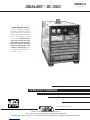
IDEALARC DC-1000
OPERATOR’S MANUAL
For use with machines Code 9919 - 9925, 10293, 11305, 11330, 11331, 11332, 11333 & 11334
IM420-C
October, 2006
Safety Depends on You
Lincoln arc welding equipment is
designed and built with safety in
mind. However, your overall safety
can be increased by proper instal-
lation ... and thoughtful operation
on your part. DO NOT INSTALL,
OPERATE OR REPAIR THIS
EQUIPMENT WITHOUT READ-
ING THIS MANUAL AND THE
SAFETY PRECAUTIONS CON-
TAINED THROUGHOUT. And,
most importantly, think before you
act and be careful.
®
• Sales and Service through Subsidiaries and Distributors Worldwide •
Cleveland, Ohio 44117-1199 U.S.A. TEL: 216.481.8100 FAX: 216.486.1751 WEB SITE: www.lincolnelectric.com
• World's Leader in Welding and Cutting Products •
Copyright © 2006 Lincoln Global Inc.

FOR ENGINE
powered equipment.
1.a. Turn the engine off before troubleshooting and maintenance
work unless the maintenance work requires it to be running.
____________________________________________________
1.b. Operate engines in open, well-ventilated
areas or vent the engine exhaust fumes
outdoors.
____________________________________________________
1.c. Do not add the fuel near an open flame
welding arc or when the engine is running.
Stop the engine and allow it to cool before
refueling to prevent spilled fuel from vaporiz-
ing on contact with hot engine parts and
igniting. Do not spill fuel when filling tank. If
fuel is spilled, wipe it up and do not start
engine until fumes have been eliminated.
____________________________________________________
1.d. Keep all equipment safety guards, covers and devices in
position and in good repair.Keep hands, hair, clothing and
tools away from V-belts, gears, fans and all other moving
parts when starting, operating or repairing equipment.
____________________________________________________
1.e. In some cases it may be necessary to remove safety
guards to perform required maintenance. Remove
guards only when necessary and replace them when the
maintenance requiring their removal is complete.
Always use the greatest care when working near moving
parts.
___________________________________________________
1.f. Do not put your hands near the engine fan.
Do not attempt to override the governor or
idler by pushing on the throttle control rods
while the engine is running.
___________________________________________________
1.g. To prevent accidentally starting gasoline engines while
turning the engine or welding generator during maintenance
work, disconnect the spark plug wires, distributor cap or
magneto wire as appropriate.
i
SAFETY
i
ARC WELDING CAN BE HAZARDOUS. PROTECT YOURSELF AND OTHERS FROM POSSIBLE SERIOUS INJURY OR DEATH.
KEEP CHILDREN AWAY. PACEMAKER WEARERS SHOULD CONSULT WITH THEIR DOCTOR BEFORE OPERATING.
Read and understand the following safety highlights. For additional safety information, it is strongly recommended that you
purchase a copy of “Safety in Welding & Cutting - ANSI Standard Z49.1” from the American Welding Society, P.O. Box
351040, Miami, Florida 33135 or CSA Standard W117.2-1974. A Free copy of “Arc Welding Safety” booklet E205 is available
from the Lincoln Electric Company, 22801 St. Clair Avenue, Cleveland, Ohio 44117-1199.
BE SURE THAT ALL INSTALLATION, OPERATION, MAINTENANCE AND REPAIR PROCEDURES ARE
PERFORMED ONLY BY QUALIFIED INDIVIDUALS.
WARNING
Mar ‘95
ELECTRIC AND
MAGNETIC FIELDS
may be dangerous
2.a. Electric current flowing through any conductor causes
localized Electric and Magnetic Fields (EMF). Welding
current creates EMF fields around welding cables and
welding machines
2.b. EMF fields may interfere with some pacemakers, and
welders having a pacemaker should consult their physician
before welding.
2.c. Exposure to EMF fields in welding may have other health
effects which are now not known.
2.d. All welders should use the following procedures in order to
minimize exposure to EMF fields from the welding circuit:
2.d.1.
Route the electrode and work cables together - Secure
them with tape when possible.
2.d.2. Never coil the electrode lead around your body.
2.d.3. Do not place your body between the electrode and
work cables. If the electrode cable is on your right
side, the work cable should also be on your right side.
2.d.4. Connect the work cable to the workpiece as close as
possible to the area being welded.
2.d.5. Do not work next to welding power source.
1.h. To avoid scalding, do not remove the
radiator pressure cap when the engine is
hot.
CALIFORNIA PROPOSITION 65 WARNINGS
Diesel engine exhaust and some of its constituents
are known to the State of California to cause can-
cer, birth defects, and other reproductive harm.
The engine exhaust from this product contains
chemicals known to the State of California to cause
cancer, birth defects, or other reproductive harm.
The Above For Diesel Engines The Above For Gasoline Engines

ii
SAFETY
ii
ARC RAYS can burn.
4.a. Use a shield with the proper filter and cover
plates to protect your eyes from sparks and
the rays of the arc when welding or observing
open arc welding. Headshield and filter lens
should conform to ANSI Z87. I standards.
4.b. Use suitable clothing made from durable flame-resistant
material to protect your skin and that of your helpers from
the arc rays.
4.c. Protect other nearby personnel with suitable, non-flammable
screening and/or warn them not to watch the arc nor expose
themselves to the arc rays or to hot spatter or metal.
ELECTRIC SHOCK can
kill.
3.a. The electrode and work (or ground) circuits
are electrically “hot” when the welder is on.
Do not touch these “hot” parts with your bare
skin or wet clothing. Wear dry, hole-free
gloves to insulate hands.
3.b. Insulate yourself from work and ground using dry insulation.
Make certain the insulation is large enough to cover your full
area of physical contact with work and ground.
In addition to the normal safety precautions, if welding
must be performed under electrically hazardous
conditions (in damp locations or while wearing wet
clothing; on metal structures such as floors, gratings or
scaffolds; when in cramped positions such as sitting,
kneeling or lying, if there is a high risk of unavoidable or
accidental contact with the workpiece or ground) use
the following equipment:
• Semiautomatic DC Constant Voltage (Wire) Welder.
• DC Manual (Stick) Welder.
• AC Welder with Reduced Voltage Control.
3.c. In semiautomatic or automatic wire welding, the electrode,
electrode reel, welding head, nozzle or semiautomatic
welding gun are also electrically “hot”.
3.d. Always be sure the work cable makes a good electrical
connection with the metal being welded. The connection
should be as close as possible to the area being welded.
3.e. Ground the work or metal to be welded to a good electrical
(earth) ground.
3.f.
Maintain the electrode holder, work clamp, welding cable and
welding machine in good, safe operating condition. Replace
damaged insulation.
3.g. Never dip the electrode in water for cooling.
3.h. Never simultaneously touch electrically “hot” parts of
electrode holders connected to two welders because voltage
between the two can be the total of the open circuit voltage
of both welders.
3.i. When working above floor level, use a safety belt to protect
yourself from a fall should you get a shock.
3.j. Also see Items 6.c. and 8.
FUMES AND GASES
can be dangerous.
5.a. Welding may produce fumes and gases
hazardous to health. Avoid breathing these
fumes and gases. When welding, keep
your head out of the fume. Use enough
ventilation and/or exhaust at the arc to keep
fumes and gases away from the breathing zone. When
welding with electrodes which require special
ventilation such as stainless or hard facing (see
instructions on container or MSDS) or on lead or
cadmium plated steel and other metals or coatings
which produce highly toxic fumes, keep exposure as
low as possible and below Threshold Limit Values (TLV)
using local exhaust or mechanical ventilation. In
confined spaces or in some circumstances, outdoors, a
respirator may be required. Additional precautions are
also required when welding on galvanized steel.
5. b. The operation of welding fume control equipment is affected
by various factors including proper use and positioning of
the equipment, maintenance of the equipment and the spe-
cific welding procedure and application involved. Worker
exposure level should be checked upon installation and
periodically thereafter to be certain it is within applicable
OSHA PEL and ACGIH TLV limits.
5.c.
Do not weld in locations near chlorinated hydrocarbon
vapors
coming from degreasing, cleaning or spraying operations.
The heat and rays of the arc can react with solvent vapors
to
form phosgene, a highly toxic gas, and other irritating prod-
ucts.
5.d. Shielding gases used for arc welding can displace air and
cause injury or death. Always use enough ventilation,
especially in confined areas, to insure breathing air is safe.
5.e. Read and understand the manufacturer’s instructions for this
equipment and the consumables to be used, including the
material safety data sheet (MSDS) and follow your
employer’s safety practices. MSDS forms are available from
your welding distributor or from the manufacturer.
5.f. Also see item 1.b.
AUG 06

FOR ELECTRICALLY
powered equipment.
8.a. Turn off input power using the disconnect
switch at the fuse box before working on
the equipment.
8.b. Install equipment in accordance with the U.S. National
Electrical Code, all local codes and the manufacturer’s
recommendations.
8.c. Ground the equipment in accordance with the U.S. National
Electrical Code and the manufacturer’s recommendations.
CYLINDER may explode
if damaged.
7.a. Use only compressed gas cylinders
containing the correct shielding gas for the
process used and properly operating
regulators designed for the gas and
pressure used. All hoses, fittings, etc. should be suitable for
the application and maintained in good condition.
7.b. Always keep cylinders in an upright position securely
chained to an undercarriage or fixed support.
7.c. Cylinders should be located:
• Away from areas where they may be struck or subjected to
physical damage.
• A safe distance from arc welding or cutting operations and
any other source of heat, sparks, or flame.
7.d. Never allow the electrode, electrode holder or any other
electrically “hot” parts to touch a cylinder.
7.e. Keep your head and face away from the cylinder valve outlet
when opening the cylinder valve.
7.f. Valve protection caps should always be in place and hand
tight except when the cylinder is in use or connected for
use.
7.g. Read and follow the instructions on compressed gas
cylinders, associated equipment, and CGA publication P-l,
“Precautions for Safe Handling of Compressed Gases in
Cylinders,” available from the Compressed Gas Association
1235 Jefferson Davis Highway, Arlington, VA 22202.
iii
SAFETY
iii
Mar ‘95
WELDING SPARKS can
cause fire or explosion.
6.a.
Remove fire hazards from the welding area.
If this is not possible, cover them to prevent
the welding sparks from starting a fire.
Remember that welding sparks and hot
materials from welding can easily go through small cracks
and openings to adjacent areas. Avoid welding near
hydraulic lines. Have a fire extinguisher readily available.
6.b. Where compressed gases are to be used at the job site,
special precautions should be used to prevent hazardous
situations. Refer to “Safety in Welding and Cutting” (ANSI
Standard Z49.1) and the operating information for the
equipment being used.
6.c. When not welding, make certain no part of the electrode
circuit is touching the work or ground. Accidental contact
can cause overheating and create a fire hazard.
6.d. Do not heat, cut or weld tanks, drums or containers until the
proper steps have been taken to insure that such procedures
will not cause flammable or toxic vapors from substances
inside. They can cause an explosion even
though
they have
been “cleaned”. For information, purchase “Recommended
Safe Practices for the
Preparation
for Welding and Cutting of
Containers and Piping That Have Held Hazardous
Substances”, AWS F4.1 from the American Welding Society
(see address above).
6.e. Vent hollow castings or containers before heating, cutting or
welding. They may explode.
6.f.
Sparks and spatter are thrown from the welding arc. Wear oil
free protective garments such as leather gloves, heavy shirt,
cuffless trousers, high shoes and a cap over your hair. Wear
ear plugs when welding out of position or in confined places.
Always wear safety glasses with side shields when in a
welding area.
6.g. Connect the work cable to the work as close to the welding
area as practical. Work cables connected to the building
framework or other locations away from the welding area
increase the possibility of the welding current passing
through lifting chains, crane cables or other alternate cir-
cuits. This can create fire hazards or overheat lifting chains
or cables until they fail.
6.h. Also see item 1.c.

iv
SAFETY
iv
PRÉCAUTIONS DE SÛRETÉ
Pour votre propre protection lire et observer toutes les instructions
et les précautions de sûreté specifiques qui parraissent dans ce
manuel aussi bien que les précautions de sûreté générales suiv-
antes:
Sûreté Pour Soudage A L’Arc
1. Protegez-vous contre la secousse électrique:
a. Les circuits à l’électrode et à la piéce sont sous tension
quand la machine à souder est en marche. Eviter toujours
tout contact entre les parties sous tension et la peau nue
ou les vétements mouillés. Porter des gants secs et sans
trous pour isoler les mains.
b. Faire trés attention de bien s’isoler de la masse quand on
soude dans des endroits humides, ou sur un plancher
metallique ou des grilles metalliques, principalement dans
les positions assis ou couché pour lesquelles une grande
partie du corps peut être en contact avec la masse.
c. Maintenir le porte-électrode, la pince de masse, le câble
de soudage et la machine à souder en bon et sûr état
defonctionnement.
d.Ne jamais plonger le porte-électrode dans l’eau pour le
refroidir.
e. Ne jamais toucher simultanément les parties sous tension
des porte-électrodes connectés à deux machines à souder
parce que la tension entre les deux pinces peut être le
total de la tension à vide des deux machines.
f. Si on utilise la machine à souder comme une source de
courant pour soudage semi-automatique, ces precautions
pour le porte-électrode s’applicuent aussi au pistolet de
soudage.
2. Dans le cas de travail au dessus du niveau du sol, se protéger
contre les chutes dans le cas ou on recoit un choc. Ne jamais
enrouler le câble-électrode autour de n’importe quelle partie
du corps.
3. Un coup d’arc peut être plus sévère qu’un coup de soliel,
donc:
a. Utiliser un bon masque avec un verre filtrant approprié
ainsi qu’un verre blanc afin de se protéger les yeux du ray-
onnement de l’arc et des projections quand on soude ou
quand on regarde l’arc.
b. Porter des vêtements convenables afin de protéger la
peau de soudeur et des aides contre le rayonnement de
l‘arc.
c. Protéger l’autre personnel travaillant à proximité au
soudage à l’aide d’écrans appropriés et non-inflammables.
4. Des gouttes de laitier en fusion sont émises de l’arc de
soudage. Se protéger avec des vêtements de protection libres
de l’huile, tels que les gants en cuir, chemise épaisse, pan-
talons sans revers, et chaussures montantes.
5. Toujours porter des lunettes de sécurité dans la zone de
soudage. Utiliser des lunettes avec écrans lateraux dans les
zones où l’on pique le laitier.
6. Eloigner les matériaux inflammables ou les recouvrir afin de
prévenir tout risque d’incendie dû aux étincelles.
7. Quand on ne soude pas, poser la pince à une endroit isolé de
la masse. Un court-circuit accidental peut provoquer un
échauffement et un risque d’incendie.
8. S’assurer que la masse est connectée le plus prés possible
de la zone de travail qu’il est pratique de le faire. Si on place
la masse sur la charpente de la construction ou d’autres
endroits éloignés de la zone de travail, on augmente le risque
de voir passer le courant de soudage par les chaines de lev-
age, câbles de grue, ou autres circuits. Cela peut provoquer
des risques d’incendie ou d’echauffement des chaines et des
câbles jusqu’à ce qu’ils se rompent.
9. Assurer une ventilation suffisante dans la zone de soudage.
Ceci est particuliérement important pour le soudage de tôles
galvanisées plombées, ou cadmiées ou tout autre métal qui
produit des fumeés toxiques.
10. Ne pas souder en présence de vapeurs de chlore provenant
d’opérations de dégraissage, nettoyage ou pistolage. La
chaleur ou les rayons de l’arc peuvent réagir avec les vapeurs
du solvant pour produire du phosgéne (gas fortement toxique)
ou autres produits irritants.
11. Pour obtenir de plus amples renseignements sur la sûreté,
voir le code “Code for safety in welding and cutting” CSA
Standard W 117.2-1974.
PRÉCAUTIONS DE SÛRETÉ POUR
LES MACHINES À SOUDER À
TRANSFORMATEUR ET À
REDRESSEUR
1. Relier à la terre le chassis du poste conformement au code de
l’électricité et aux recommendations du fabricant. Le dispositif
de montage ou la piece à souder doit être branché à une
bonne mise à la terre.
2. Autant que possible, I’installation et l’entretien du poste seront
effectués par un électricien qualifié.
3. Avant de faires des travaux à l’interieur de poste, la debranch-
er à l’interrupteur à la boite de fusibles.
4. Garder tous les couvercles et dispositifs de sûreté à leur
place.
Mar. ‘93

-6-
Thank You for selecting a QUALITY product by Lincoln Electric. We want you
to take pride in operating this Lincoln Electric Company product
••• as much pride as we have in bringing this product to you!
Read this Operators Manual completely before attempting to use this equipment. Save this manual and keep it
handy for quick reference. Pay particular attention to the safety instructions we have provided for your protection.
The level of seriousness to be applied to each is explained below:
WARNING
This statement appears where the information must be followed exactly to avoid serious personal injury or
loss of life.
This statement appears where the information must be followed to avoid minor personal injury or damage to
this equipment.
CAUTION
Please Examine Carton and Equipment For Damage Immediately
When this equipment is shipped, title passes to the purchaser upon receipt by the carrier. Consequently, Claims
for material damaged in shipment must be made by the purchaser against the transportation company at the
time the shipment is received.
Please record your equipment identification information below for future reference. This information can be
found on your machine nameplate.
Product _________________________________________________________________________________
Model Number ___________________________________________________________________________
Code Number or Date Code_________________________________________________________________
Serial Number____________________________________________________________________________
Date Purchased___________________________________________________________________________
Where Purchased_________________________________________________________________________
Whenever you request replacement parts or information on this equipment, always supply the information you
have recorded above. The code number is especially important when identifying the correct replacement parts.
On-Line Product Registration
- Register your machine with Lincoln Electric either via fax or over the Internet.
• For faxing: Complete the form on the back of the warranty statement included in the literature packet
accompanying this machine and fax the form per the instructions printed on it.
• For On-Line Registration: Go to our
WEB SITE at www.lincolnelectric.com. Choose “Quick Links” and then
“Product Registration”. Please complete the form and submit your registration.

-7-
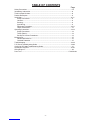
TABLE OF CONTENTS
Page
Safety Precautions .............................................................................................................2-5
Introductory Information .......................................................................................................6
Technical Specifications ......................................................................................................8
Product Description..............................................................................................................9
Installation .........................................................................................................................9-12
Safety Precautions ........................................................................................................9
Location .........................................................................................................................9
Stacking.........................................................................................................................9
Input Wiring ...................................................................................................................9
Reconnect Procedures ..............................................................................................10-11
Output Connections......................................................................................................12
Operating Instructions ......................................................................................................13-14
Safety Precautions .......................................................................................................13
To Set Polarity ..............................................................................................................13
Set-Up For Various Procedures ...................................................................................14
Maintenance .......................................................................................................................15
General Maintenance ...................................................................................................15
Overload Protection......................................................................................................15
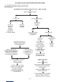
Troubleshooting................................................................................................................16-18
P.C. Board Troubleshooting Guide ..................................................................................19-20
Outline for DC-1000 Troubleshooting Guide.......................................................................21
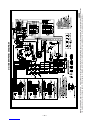
Connection Diagrams.......................................................................................................22-25
Wiring Diagram ...................................................................................................................26
Parts Lists ...................................................................................................................P146 Series

– 8–
60% Duty Cycle
215/108
86
215/124/108
124/94
113
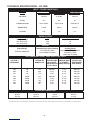
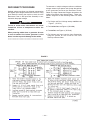
TECHNICAL SPECIFICATIONS – DC-1000
Volts at Rated Amperes
44
44
44
Auxiliary Power
See the OPERATION section
for Auxiliary Power
information by model
Amps
1000
1140
1250
Maximum Open Circuit Voltage
75V for 60 HZ models
72V for 50/60 HZ models
Duty Cycle
100% Duty Cycle
60% Duty Cycle
50% Duty Cycle
Output Range
150A/16V-1300A/46V
INPUT - THREE PHASE ONLY
OUTPUT
1Also called “inverse time” or “thermal/magnetic” circuit breakers; circuit breakers which have a delay in tripping action that decreases as the magnitude of the current increases.
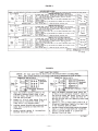
RECOMMENDED INPUT WIRE AND FUSE SIZES
Standard
Voltage
230/460/60
575/60
220/380/440/50/60
380/500/50/60
415/50/60
100% Duty Cycle
193/96.5
77.2
193/112/96.5
112/85
102
50% Duty Cycle
230/115
92
230/133/115
133/101
121
Input Current at Rated Output
RATED OUTPUT
INPUT
VOLTAGE /
FREQUENCY
230
460
575
220
380
415
440
500
TYPE 75°C
(SUPER LAG)
OR BREAKER
SIZE (AMPS)1
300 Amp
150 Amp
125 Amp
300 Amp
175 Amp
150 Amp
150 Amp
125 Amp
TYPE 75°C
GROUND WIRE
IN CONDUIT
AWG(IEC-MM2) SIZES
4 (21)
6 (14)
6 (14)
4 (21)
6 (14)
6 (14)
6 (14)
6 (14)
TYPE 75°C
COPPER WIRE
IN CONDUIT
AWG(IEC-MM2) SIZES
30°C (86°F) Ambient
000 (85)
3 (27)
4 (21)
000 (85)
2 (34)
2 (34)
3 (27)
4 (21)
INPUT AMPERE
RATING ON
NAMEPLATE
193
96.5
77.2
193
112
102
96.5
85
HERTZ
60
60
60
50/60
50/60
50/60
50/60
50/60
PHYSICAL DIMENSIONS
HEIGHT
30.75 in
781 mm
WIDTH
22.25 in
567 mm
DEPTH
39.0 in
991 mm
WEIGHT
821 lbs.
372 kg.

The total enclosure, designed to permit outdoor operation,
resists dust, salt, rain, humidity, and high and low temperature
extremes.
The machine uses a 38” (965mm) long base. The low profile
case facilitates installation of the machine under a workbench
and stacking the machines two high to conserve floor space.
A permanent lifting eye is located at the top of the machine and
is positioned so that it acts as nearly as possible through the
center of gravity. This lift eye fits under the case of the second
machine without interference when stacking.
STACKING
Two DC-1000’s may be stacked by observing the following
safety precautions:
1. Make sure the first or bottom unit is setting on a level, well-
supported surface.
2. The units must be stacked with their fronts flush, making
sure the two holes in the base rails of the top unit are over
the two pins located on top of the bottom unit.
INPUT WIRING
Be sure the voltage, phase and frequency of the input power is
as specified on the welder nameplate.
Dual voltage (e.g. 230/460) models are shipped connected for
the highest voltage. To change the connection, see the connec-
tion diagram pasted to the inside of the access panel in the
case back.
Have a qualified electrician remove the rear access panel and
connect 3 phase AC power to terminals L1, L2and L3of the
input panel in accordance with the U.S. National Electrical
Code, all local codes and the wiring diagram located inside the
machine.
The welder frame must be grounded. A stud marked with the
symbol located inside the machine near the input panel is
provided for this purpose. See the U.S. National Electrical Code
for details on proper grounding methods. (See Technical
Specifications)
PRODUCT DESCRIPTION
The DC-1000 is an SCR-controlled three phase DC
power source. It is designed with a single range
potentiometer control for submerged arc or open arc
automatic and semiautomatic welding. It can be used
for air carbon arc cutting with carbon rods up to and
including 5/8” (15.9mm) dia. The DC-1000 (below
code 9500) is not recommended for stick welding or
for solid wire and gas in the short arc welding mode.
With the addition of the 500 amp output stud to DC-
1000 models above code 9500, GMAW procedures
can be performed. This connection provides the
enhanced lower current arc characteristics required
for this type of welding.
The DC-1000 is provided with a three position mode
switch that selects CV Innershield®, CV Submerged
Arc or CC (Variable Voltage) Submerged Arc.
The unit is designed to be used with the NA-5, NA-5R
and NA-3 automatics, the LT-56 and LT-7 tractors,
and can also be used with the LN-7, LN-8 or LN-9
semiautomatic wire feeders.
– 9–
INSTALLATION
ELECTRIC SHOCK can kill.
• Have an electrician install and service
this equipment.
• Turn the input power off at the fuse
box before working on equipment.
• Do not touch electrically hot parts.
---------------------------------------------------------------------
WARNING
FALLING EQUIPMENT can cause
injury.
• Do not lift this machine using lift bale if
it is equipped with a heavy accessory
such as trailer or gas cylinder.
• Lift only with equipment of adequate lifting capacity.
• Be sure machine is stable when lifting.
• Do not stack more than two high.
• Do not stack the DC-1000 on top of any other
machine.
---------------------------------------------------------------------
WARNING
LOCATION
Even though the machine is designed to operate
under a wide variety of environmental conditions, for
maximum reliability and long life the machine should
be located in a clean, dry place where there is free cir-
culation of clean air in through the front and out the
back of the machine. Dirt and dust that can be drawn
into the machine should be kept to a minimum. Failure
to observe these precautions can result in excessive
operating temperatures and nuisance shutdown of the
machine.
The case front incorporates a recessed control panel
which protects the controls and minimizes the possi-
bilities of accidental contact. This cover panel can be
flipped open to permit access to the enclosed control
section.
The individual case sides are removable for easy
access for internal service or inspection.
The case rear is equipped with a removable cover
plate, permitting easy access to the input panel.

– 10 –
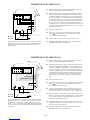
RECONNECT PROCEDURE
Multiple voltage machines are shipped connected to
the highest input voltage listed on the machine’s rating
plate. Before installing the machine, check that the
Reconnect Panel in the Input Box Assembly is con-
nected for the proper voltage.
Failure to follow these instructions can cause
immediate failure of components within the
machine.
When powering welder from a generator be sure
to turn off welder first, before generator is shut
down, in order to prevent damage to the welder
------------------------------
To reconnect a multiple voltage machine to a different
voltage, remove input power and change the position
of the reconnect board on the Reconnect Panel.
Follow The Input Connection Diagram located on the
inside of Case Back Input Access Door. These con-
nection diagrams for the following codes are listed
below.
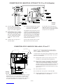
1. For Single and Dual Voltage except 380/500 see
Figure 1, (S17172).
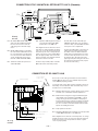
2. For 220/380/460, see Figure 2, (M14358).
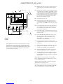
3. For 380/500, see Figure 3, (S17344).
4. For Voltages not listed, see the Input Connection
Diagram pasted on the inside of the Case
Back Input Access Door.
CAUTION
FIGURE 1


– 12 –
OUTPUT CONNECTIONS
Output Studs
The output leads are connected to the output termi-
nals. The output terminals are located on the lower
case front and labeled “+” and “-”. There are 1000
amp rated “+” terminals on the right side, one 500
amp rated “+” terminal near the center and “-” termi-
nals on the left side. They are fully recessed to mini-
mize the possibility of accidental contact by an object
or a person. Strain relief is provided by the oval holes
in the base. The leads are run through these oval
holes before they are connected to the output termi-
nals.
The 1000 amp output connections provide the full
rated output range of the machine. See Table1 for
recommended DC-1000 cable sizes for combined
lengths of electrode and work cables.
The 500 amp output connections provide enhanced
lower current arc characteristics, especially for sub-
merged arc and GMAW procedures below 450 amps.
Auxiliary Power
This machine supplies the 115 volt, AC power needed
for operating wire feeding equipment. The power is
available from terminals #31 and #32 on the terminal
strip. An 8 amp slow blow fuse on the machine control
panel protects the auxiliary power from excessive
overloads. The circuit has a 1000 volt-ampere rating.
Control Cable Connection
Terminal strips with screw connections are located
behind the hinged door on the front of the power
source to make all the control cable connections for
operating wire feeding equipment. See the appropri-
ate connection diagram for exact instructions covering
the wire feeder being used.
With the DC-1000 turned off, the control cable from
the automatic wire feeding equipment is connected to
the terminal strip. A strain relief box connector is pro-
vided for access into the terminal strip section. A
chassis grounding screw is also provided below the
terminal strip marked with the symbol for connect-
ing the wire feeding equipment grounding wire. See
the appropriate connection diagram for the exact
instructions for the wire feeder being used. A spare
hole is provided for an additional box connector if
required.
Connecting for Air Carbon Arc:
a. Turn off all power.
b. Disconnect all wire feed unit control, electrode and
work leads.
c. Connect a jumper from 2-4 on terminal strip.
d. Place mode switch in the CV(I) position.
With the DC-1000 connected for air carbon arc weld-
ing, the output terminals will be energized at all times.
Cable SizeParallel CablesCable Length
1/0 (53mm2)3
3
3
Lengths up to 150 ft. (46m)
2/0 (67mm2)150 ft.(46m) to 200 ft (61m)
3/0 (85mm2)200 ft.(61m) to 250 ft.(76m)
TABLE 1
DC-1000 Cable Sizes for Combined Lengths of Copper Electrode and Work Cable
at 100% Duty Cycle
ELECTRODE, WORK AND #21 LEAD

– 13 –
OPERATING INSTRUCTIONS
NOTE: All P.C. boards are protected by a moisture
resistant coating. When the welder is operated, this
coating will “bake off” of certain power resistors that
normally operate at high temperatures emitting some
smoke and odor for a short time. These resistors and
the P.C. board beneath them may become blackened.
This is a normal occurrence and does not damage the
component or affect the machine performance.
TO SET POLARITY
Turn off the DC-1000 and connect the electrode cable
to the “Positive” or “Negative” studs depending upon
the electrode polarity desired. Connect the work cable
to the other stud. (See “Output Connections”).
Set the “Electrode Negative-Electrode Positive” switch
to correspond to the polarity of the electrode cable
connection. This switch setting is necessary for proper
operation of some Lincoln wire feeders and does not
change the welding polarity.
Starting the Machine - The push button power “on”
switch at the extreme right side of the control panel
energizes and closes the three phase input contactor
from a 115 volt auxiliary transformer. This in turn ener-
gizes the main power transformer.
The red light below the stop-start button indicates
when the input contactor is energized.
Output Control - The output control in the center of
the control panel is a continuous control of the
machine output. The control may be rotated from min.
to max. while under load to adjust the machine output.
The machine is equipped with line voltage compensa-
tion as a standard feature. This will hold the output rel-
atively constant except at maximum output of the
machine, through a fluctuation of +/- 10% of input line
voltage.
Output Control at DC-1000 or Output Control
Remote Switch
The toggle switch on the control panel labeled “Output
Control at DC-1000” / “Output Control Remote” gives
the operator the option of controlling the output at the
machine control panel or at a remote station. For
remote control, the toggle switch is set in the “Output
Control Remote” position and controlled at the wire
feed unit control or by connecting a K775 control to
the appropriate terminals (as indicated on the connec-
tion diagram) on the terminal strip at the front of the
machine. For control at the machine control panel, the
toggle switch is set in the “Output Control at DC-1000”
position.
Remote Output Control - (Optional)
The K775 Remote Output Control consists of a control
box with 28 ft. (8.4m) of four conductor cable. This
connects to terminals 75, 76, 77 on the terminal strip,
and the case grounding screw so marked with the
symbol on the machine. These terminals are
made available by opening the terminal access cover
on the left side of the case front. This control will give
the same control as the output control on the
machine.
Mode Switch
The toggle switch labeled C (I) Innershield, CV(S)
Submerged Arc, CC (or Variable Voltage) is used to
select the proper welder characteristics for the
process being used. The CC (or Variable Voltage)
mode is primarily available for use with older wire
feeding equipment such as the LAF-3, LT-34 and so
forth. Use of this type of older equipment requires the
addition of an NL Option Kit.
ELECTRIC SHOCK can kill.
• Do not touch electrically live parts or
electrode with skin or wet clothing.
• Insulate yourself from work and
ground.
• Always wear dry insulating gloves.
------------------------------------------------------------------------
FUMES AND GASES can be danger-
ous.
• Keep your head out of fumes.
• Use ventilation or exhaust to remove
fumes from breathing zone.
------------------------------------------------------------------------
WELDING SPARKS can cause fire or
explosion.
• Keep flammable material away.
• Do not weld on closed containers.
------------------------------------------------------------------------
ARC RAYS can burn eyes and skin.
• Wear eye, ear and body
protection.
------------------------------------------------------------
See additional warning information at
front of this operator’s manual.
-----------------------------------------------------------
WARNING

– 14 –
Set-Up for Various Procedures
1. Selection of mode switch position - There are
several general rules to follow in the selection of
the mode switch position.
a. Use the CV(I) mode for all FCAW and GMAW
processes. The CV(I) mode is also used for
air carbon arc using carbon rods up to and
including 5/8” (15.9mm) dia.
Welding with NR®-151, 202, 203 and other
electrodes below 20 volts, is not recommend-
ed.
b. Use the CV(S) mode for all submerged arc
welding. This applies to both low and high
travel speeds.
c. The CC (Variable Voltage) mode is available
for high current large puddle submerged arc
procedures that cannot be done as well with
the constant voltage mode. CC mode should
be used for 3/16” (4.8mm) diameter electrode
and above where high current surges cause
machine shutdown when starting. This occurs
primarily when the slag ball is not cut from the
electrode prior to starting. (Also requires a
wire feeder that has a constant current mode
- i.e. NA-3S).
NOTE: Some processes and procedures may be bet-
ter with the mode switch in the other CV position. If
the mode switch position initially selected is not pro-
ducing the desired results, then place the mode switch
in the other CV position and make a test weld. Then
use the CV mode switch position that gives the
desired results.
2. NA-3 - The NA-3 should be set for the mode being
used on the power source. If using either of the
CV modes, the NA-3 CC board switch should be
set for CV. If the power source is used in the CC
mode, then the NA-3 CC board mode switch
should be placed in the CC position.
All the NA-3’s when used with the DC-1000 are capa-
ble of cold starting with the constant current board
mode switch in CC. Cold starting permits the wire to
be inched down to the work, automatically stop, and
automatically energize the flux hopper valve. All NA-
3’s made after September, 1976 are capable of cold
starting on either CV or CC settings of the constant
current board.
On the NA-3, set the open circuit voltage control to the
same dial setting as the arc voltage control. If the pro-
cedure has not yet been established, a good starting
point is to set the OCV to #6.
Run a test weld, setting the proper current, voltage
and travel speed. Once the proper welding procedure
is established and if the start is poor - wire blast off,
stub, etc. - adjust the NA-3 OCV and inch speed con-
trols for optimum starting. In general, a low inch speed
and an OCV dial setting identical to the voltage dial
setting will provide the best starting.
To further optimize starting, adjust the OCV by making
repeated starts and observing the NA-3 voltmeter
action. With proper adjustment of the OCV control, the
voltmeter needle will swing smoothly up to the desired
arc voltage and thus provide repeatable starts.
If the voltmeter swings above the set voltage and then
back to the desired welding voltage, the OCV setting
is too high. This usually results in a bad start where
the wire tends to “blast off”.
If the voltmeter needle hesitates before coming up to
the desired voltage, the OCV is set too low. This will
cause the electrode to stub.
3. NA-5 - Set the DC-1000 mode switch to the
process being used - CV(I) Innershield or CV(S)
Sub Arc. Set the DC-1000 machine/remote switch
in the remote position. Set the OCV control four
volts higher than the welding voltage and the inch
speed at 1/2 the welding wire feed speed for the
initial test weld. Adjust the OCV and inch speed as
required for optimum starting. Refer to the NA-5
instruction manual for data regarding the setup of
controls and modes on the NA-5.
4. LN-8 - Set the LN-8 mode switch (located on the
CC board) to the CV position. Set the DC-1000
mode switch on CV(I) Innershield or CV(S) Sub
Arc according to the process being used.
5. LN-7, LN-9 and other constant wire feed units -
Set the DC-1000 mode switch on CV(I) Innershield
or CV(S) Sub Arc according to the process being
used. If using an LN-9, refer to the LN-9 instruction
manual for further instructions on its use. If using
an LN-7, it will be necessary to use either a K775
Remote Control or operate the DC-1000 with the
machine/remote switch in the machine position.
NL Option Kit (Not Required with NA-3, NA-5, LT-7
or LT-56).
The K783 NL Option Kit (for field installation) is
designed to permit use of the obsolete NA-2, LAF-3,
LT-3 and LT-3 section of the LT-34 tractor. It provides
the necessary DC control power for the operation of
the equipment and the necessary circuitry for proper
inching, cold starting and arc striking. In using the NL
Option Kit, a K775 remote field control is required and
is included as part of the kit. Installation instructions
are included with the NL Option Kit.

– 15 –
MAINTENANCE
ELECTRIC SHOCK can kill.
• Have an electrician install and service
this equipment.
• Turn the input power off at the fuse
box before working on equipment.
• Do not touch electrically hot parts.
---------------------------------------------------------------------
WARNING
GENERAL MAINTENANCE
1. The fan motors have sealed bearings which
require no service.
2. In extremely dusty locations, dirt may clog the air
channels causing the welder to run hot. Blow out
the welder with low pressure air at regular inter-
vals as required to eliminate excessive dirt and
dust buildup on internal parts.
OVERLOAD PROTECTION
The power source is thermostatically protected with
two proximity thermostats against overload or insuffi-
cient cooling. One thermostat is located on the trans-
former secondary Negative Output Lead, and the
other thermostat is located on the choke coil. The
thermostats are connected in series in the machine
control circuit so that if an excessive overload is
applied to the machine, or the machine should receive
insufficient cooling on either the main transformer,
SCR bridge assembly or choke, the input contactor
would open and remain open until the machine cools.
It can then be manually restarted by operating the
start push button.
The power source is also protected against heavy
overloads on the SCR bridge assembly through an
electronic protection circuit. This circuit senses an
overload on the power source and opens the input
contactor should the overload remain for a predeter-
mined time. The predetermined time varies with the
amount of overload; the greater the overload, the
shorter the time. The input contactor will remain open
until the power source is manually started with the
start push button.
The control board is designed with adequate protec-
tion so that no damage will occur if the remote control
leads are shorted together or are grounded to the
case. The machine will automatically shut down if
such faults do occur.
An 8-amp fuse located on the machine control panel
protects the 115 volt auxiliary AC circuit (#31 and #32)
from overload. If replacing, use the same type and
size fuse.

– 16 –
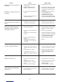
Input contactor (1CR) chatters.
Machine input contactor does not
operate.
Input contactor pulls in when start
button is pressed, but immediately
drops out.
Machine input contactor operates but
no output when trying to weld.
a. Faulty input contactor (1CR).
b. Low line voltage.
c. Faulty 2CR relay.
a. Supply line fuse blown.
b. Contactor power circuit dead.
c. Broken power lead.
d. Wrong input voltage.
e. Secondary or choke thermostat
open.
f. Open input contactor coil.
g. Faulty stop/start push button
switch.
h. Faulty 2CR relay.
i. Defective control board.
a. Defective start/stop push button.
b. Defective 1CR interlock.
c. Ground fault between control ter-
minals 73, 74, 75, 76 or 77 and
negative output terminal.
d. Short on output terminals with 2-4
jumpered.
e. Defective control board.
a. Electrode or work lead loose or
broken.
b. Open main transformer (T1) pri-
mary or secondary circuit.
c. Output pilot relay 4CR not operat-
ing or faulty.
d. Firing circuit P.C. board not con-
nected or is faulty.
e. If using 500 amp stud, choke cir-
cuit may be open.
a. Repair or replace.
b. Check input power.
c. Repair relay.
a. Replace if blown - look for reason
first.
b. Check pilot transformer T2 and
associated leads.
c. Check input voltage at contactor.
d. Check voltage against instruc-
tions.
e. Check for overheating; make sure
fan is operating and there is no
obstruction to free air flow.
Replace faulty thermostat.
f. Replace coil.
g. Replace switch.
h. Replace relay.
i. Replace control board. See P.C.
board troubleshooting guide.
a. Check and replace if necessary.
b. Repair or replace.
c. Check 73, 74, 75, 76 or 77 for
ground to negative output circuit.
d. Remove short.
e. Replace control board. See P.C.
board troubleshooting guide.
a. Repair connection.
b. Repair.
c. Check relay pull-in by connecting
a jumper across terminals 2 and 4
on DC-1000 terminal strip.
Replace if faulty.
d. All nine light emitting diodes
(LED1 thru LED9) must be lit. See
P.C. board troubleshooting guide.
e. Repair.
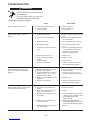
Trouble Cause What To Do
TROUBLESHOOTING
ELECTRIC SHOCK can kill.
• Have an electrician install and service
this equipment.
• Turn the input power off at the fuse
box before working on equipment.
• Do not touch electrically hot parts.
---------------------------------------------------------------------
WARNING

– 17 –
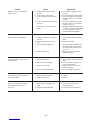
Machine has maximum output but
not control.
Machine has minimum output and
no control.
Machine does not have maximum
output.
Machine has output but trips off
immediately when wire feed unit
start button is pressed.
Variable or sluggish welding arc.
Machine will not shut off.
Output control not functioning on
the machine(1).
a. Output control switch (SW3) in
wrong position.
b. Output control switch faulty.
c. Open in feedback circuitry.
d. Faulty control or firing circuit P.C.
boards.
e. Output control potentiometer cir-
cuit open (Lead 75).
a. Terminals 73, 74, 75, 76 or 77
grounded to positive output.
a. One input fuse blown.
b. One phase of main transformer
open.
c. Faulty control or firing circuit P.C.
boards.
d. Output control potentiometer
defective.
e. Output control potentiometer
leads open - 76, 77, 226, 236,
237, 238.
a. Machine has either an internal or
external short circuit on the out-
put.
b. Faulty control P.C. board.
c. Terminals 73, 74, 75, 76, 77
grounded to negative output termi-
nal.
a. Poor work or electrode connec-
tion.
b. Welding leads too small.
c. Welding current or voltage too
low.
d. Defective main SCR bridge.
a. Input contactor contacts frozen.
b. Faulty 2CR relay.
a. Check position of switch.
b. Check switch and replace if faulty.
c. Check wiring and control and fir-
ing circuit P.C. board wiring har-
ness plugs.
d. All light emitting diodes must be
lit, except LED4 on the
control/fault board. See P.C.
board troubleshooting guide.
e. Check and replace potentiometer
if faulty. Check wiring of Lead #75.
a. Check 73, 74, 75, 76 or 77 for
ground to positive output circuit.
a. Check and replace if blown after
checking for reason for blown
fuse.
b. Check for open and repair.
c. All light emitting diodes must be lit
on both P.C. boards, except LED4
on control/fault board. See P.C.
board troubleshooting guide.
d. Check and replace if faulty.
e. Repair.
a. Check internally and externally for
any shorts and remove or repair.
b. Replace control board. See P.C.
board troubleshooting guide.
c. Check for grounded 73, 74, 75,
76, 77.
a. Check and clean all connections.
b. Check table in instruction manual.
c. Check procedures for recom-
mended settings.
d. Check and replace if defective.
a. Check and replace if necessary.
b. Check and replace if necessary.
Trouble Cause What To Do
(1) If connected to an LN-9 or NA-5, disconnect leads 73, 74, 75 before troubleshooting.

– 18 –
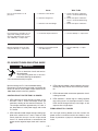
Output control not functioning on
remote control.
Poor starting on CV(S) Sub-Arc.
Poor bead shape or erratic arc on
CV(S) Sub-Arc.
Poor starting on CV(I) Innershield
and CV(S) Sub-Arc.
Poor arc characteristics on CV(I)
Innershield or other open arc
processes.
a. Output control switch in wrong
position.
b. Faulty output control switch.
c. Faulty remote control potentiome-
ter.
d. Leads or connections open in con-
trol circuit.
e. Faulty firing or control circuit P.C.
board.
a. Improper procedures or setting of
controls.
b. Poor electrode or work connec-
tion.
c. 3CR reed switch inoperative.
d. Faulty control board.
a. Improper procedures.
b. Defective 3CR reed switch.
c. Faulty control board.
d. Defective main SCR bridge.
a. Defective 3CR reed switch.
b. Faulty control board.
a. Mode switch in CV(S) Sub-Arc
mode.
b. Defective main SCR bridge.
a. Place switch in “Output Control
Remote”.
b. Check and replace if found faulty.
c. Check and replace if found faulty.
(Voltage from 75 to 77 should be
3 to 5V).
d. Check all leads and connections,
internal or remote, for continuity;
repair if necessary.
e. All light emitting diodes must be lit
on both P.C. boards, except LED4
on control/fault board. See P.C.
board troubleshooting guide.
a. See instruction manual and proce-
dures.
b. Repair connections.
c. Check reed switch voltage leads
216 to 220. Idle voltage is about
8V; when welding, voltage must
go to zero.
d. Replace. See P.C. board trou-
bleshooting guide.
a. See instruction manual and proce-
dures.
b. Check reed switch per item c. of
previous Table above.
c. Replace. See P.C. board trou-
bleshooting guide.
d. Check and replace if defective.
a. Replace.
b. Replace.
a. Place mode switch in CV(I)
Innershield mode.
b. Check and replace if defective.
Trouble Cause What To Do

– 19 –
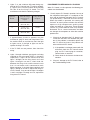
Poor arc characteristics on all
processes.
Poor performance (including arc out-
ages) while welding at low current
(less than 450 amps) when connect-
ed to 1000 amp “+” output studs.
Machine frequently shuts off while
using the 500 amp “+” output stud.
a. Defective control board.
b. Defective firing board.
c. Defective main SCR bridge.
a. Insufficient output inductance.
a. Effective current demand well
over 500 amperes.
a. Check and replace if defective.
See P.C. board troubleshooting
guide.
b. Check and replace if defective.
See P.C. board troubleshooting
guide.
c. Check and replace if defective.
a. Use the 500 amp “+” output stud.
a. Use the 1000 amp “+” output
studs.
Trouble Cause What To Do
P.C. BOARD TROUBLESHOOTING GUIDE
ELECTRIC SHOCK can kill.
• Have an electrician install and service
this equipment.
• Turn the input power off at the fuse
box before working on equipment.
• Do not touch electrically hot parts.
---------------------------------------------------------------------
WARNING
Machine settings for P.C. board troubleshooting.
Disconnect all leads to the wire feeder and jumper ter-
minals #2 and #4 on DC-1000. Output Control at DC-
1000. Mode switch in the CV(I) position.
CONTROL/FAULT PROTECTION P.C. BOARD
1. LED1 indicates AC input voltage is present at pins
255-256. If not lit, check the voltage across the
secondary winding of the control transformer, T2.
The voltage should be approximately 115 volts. If
not, the problem is in the power supply and not the
P.C. board.
2. LED2 indicates welder output voltage is being sup-
plied to the control circuit. If not lit, check to make
certain lead 222 from pin 2 of the 15-pin control
circuit P.C. board connector is connected to the
power source negative output lead and is not bro-
ken.
3. LED3 indicates power is being applied to fault pro-
tection pilot relay 2CR to turn on the input contac-
tor.
4. LED4 indicates when overcurrent protection circuit
is being activated.
5. LED5 indicates a control signal is being supplied
to the firing circuit. As the output control is varied,
LED5 should change brilliancy from bright at low
output to dim at high output.
FIRING CIRCUIT P.C. BOARD
All nine light emitting diodes must be lit when the
power source is turned on and the wire feed arc start
button is pressed or a jumper is connected between 2
and 4.

1. Lights 7, 8, and 9 indicate AC power being sup-
plied to the P.C. boards from T1 auxiliary winding.
If a light is not lit, turn the machine off and unplug
P5 from J5 on the firing P.C. board. Turn the
machine on and check the following voltages:
– 20 –
PROCEDURE FOR REPLACING P.C. BOARDS
When P.C. board is to be replaced, the following pro-
cedure must be followed:
1. Visually inspect P.C. board in question. Are any of
the components damaged? Is a conductor on the
back side of the board damaged? All P.C. boards
are protected by a moisture resistant coating.
When the welder is operated, this coating will
“bake off” of certain power resistors that normally
operate at high temperatures emitting some
smoke and odor for a short time. These resistors
and the P.C. board beneath them may become
blackened. This is a normal occurrence and does
not damage the component or affect the machine
performance.
a. If there is no damage to the P.C. board, insert
a new one and see if this remedies the prob-
lem. If the problem is remedied, replace the
old P.C. board and see if the problem still
exists with the old P.C. board.
1) If the problem is no longer present with the
old board, check the P.C. board harness
plug and P.C. board plug for corrosion,
contamination, or oversize.
2) Check leads in the harness for loose con-
nections.
b. If there is damage to the P.C. board, refer to
the Troubleshooting Guide
Light That Check AC Voltage Voltage Should
Was Off Between Pins of Be Approx.
Plug P5
7 P5 Pins 2 & 4 75 VAC
(Wires 203, 204)
8 P5 Pins 7 & 3 75 VAC
(Wires 205, 206)
9 P5 Pins 9 & 8 75 VAC
(Wires 207, 208)
• If approximately 75 VAC is present, turn the
machine off, plug P5 back into firing board. Turn
the machine back on and check to see if the light
or lights are on. If the light or lights are not on
replace the firing P.C. board.
• If the 75 VAC was not present, then check the
wiring.
2. Lights 1 through 6 indicate gate signals are being
supplied to the main power SCR’s 1 through 6
respectively. If light 5 on the control circuit and
lights 7 through 9 on the firing circuit are lit and
lights 1 through 6 are not lit, check lead 231
between the firing circuit and the control circuit
that it is not broken and is connected to each
Molex connector. If the lead shows continuity and
lights 1 through 6 are not lit, replace the firing cir-
cuit P.C. board. If any one of the lights 1 through 6
is not lit and lights 7 through 9 are lit, replace the
firing circuit P.C. board.
La page est en cours de chargement...
La page est en cours de chargement...
La page est en cours de chargement...
La page est en cours de chargement...
La page est en cours de chargement...
La page est en cours de chargement...
La page est en cours de chargement...
La page est en cours de chargement...
La page est en cours de chargement...
La page est en cours de chargement...
-
 1
1
-
 2
2
-
 3
3
-
 4
4
-
 5
5
-
 6
6
-
 7
7
-
 8
8
-
 9
9
-
 10
10
-
 11
11
-
 12
12
-
 13
13
-
 14
14
-
 15
15
-
 16
16
-
 17
17
-
 18
18
-
 19
19
-
 20
20
-
 21
21
-
 22
22
-
 23
23
-
 24
24
-
 25
25
-
 26
26
-
 27
27
-
 28
28
-
 29
29
-
 30
30


Lincoln Electric Idealarc DC-1000 Manuel utilisateur
- Catégorie
- Système de soudage
- Taper
- Manuel utilisateur
dans d''autres langues
Documents connexes
-
Lincoln Electric Invertec V130-S Mode d'emploi
-
-
-
-
-
Lincoln Electric IM756-A Manuel utilisateur
-
-
-