echoflex ELEDR-RH Guide d'installation

Taper
Guide d'installation
Echoflex Installation Guide
Power Load Controller
Corporate Headquarters Middleton, WI, USA | Phone +1 608 831 4116
Web echoflexsolutions.com | Email [email protected] | Support [email protected]
© 2021 Echoflex Solutions, Inc. Trademark and patent info: echoflexsolutions.com/ip
Echoflex intends this document to be provided in its entirety. Product information and specifications subject to change.
8189M2130 Rev B Released 2021-04
Overview
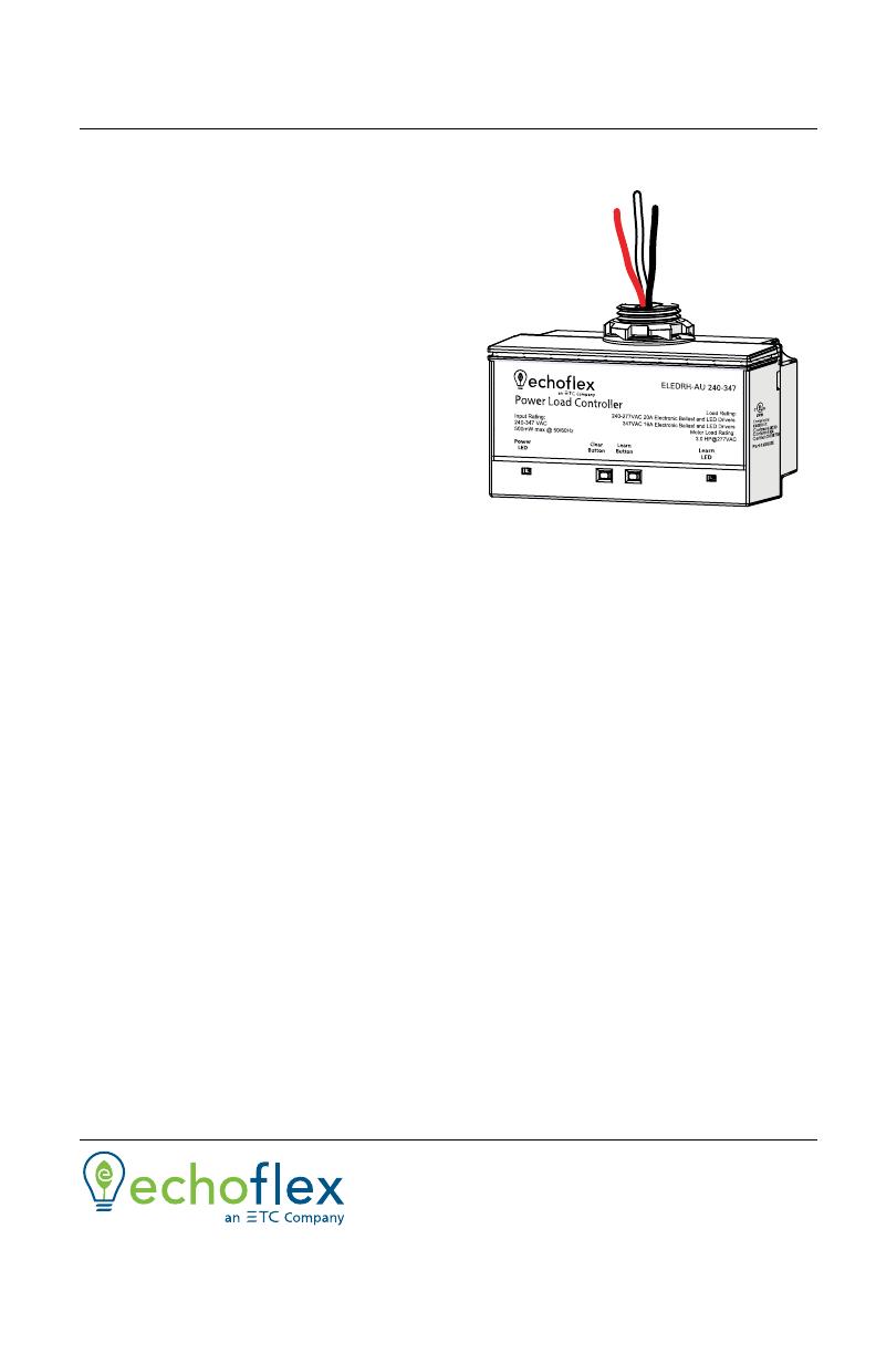
The ELEDR Power Load Controller
is used to switch circuits for
lighting, motor, receptacle, or
general purpose loads. It receives
input from linked wireless devices
or gateways based on switch
stations, room occupancy state,
ambient light levels, scheduled
events and network commands.
The ELEDR can also provide
process control for circuit or fan
control applications eliminating
long wire runs.
This document covers installation
of ELEDR(H) Power Load
Controller models. The Echoflex Power Load Controller ELEDR Configuration
Guide is available for download at echoflexsolutions.com.
The package contents includes the controller and the installation guide.
Prepare for Installation
Echoflex recommends paying special attention to the installation
environment.
High density construction materials and large metal appliances or
fixtures in the space may disrupt wireless reception.
Mount the controller to an electrical junction box or a panel in a
location and at a height where it is not subject to tampering by
unauthorized personnel.
Supplies required to install the controller (not provided):
Appropriately sized wire nuts
Wire insulation
Small cable ties
High voltage
model shown
Echoflex Installation Guide
Power Load Controller
Power Load Controller Page 2 of 8 Echoflex
IMPORTANT SAFEGUARDS
READ AND FOLLOW ALL SAFETY INSTRUCTIONS
.
.
This product is suitable for use in dry locations where the ambient
temperature is -5°C to 50°C (23°F to 122°F).
Do not use outdoors.
Do not mount near gas or electric heaters
Equipment should be mounted in locations and at heights where it is
not subject to tampering by unauthorized personnel.
The use of accessory equipment not recommended by the
manufacturer may cause an unsafe condition.
Do not use this equipment for other than its intended use.
Servicing should be performed by qualified service personnel.
Pollution Degree: 2.
SAVE THESE INSTRUCTIONS
WARNING: Risk of electric shock! This device utilizes high
voltage and should only be installed by a qualified installer or
electrician. Follow all local codes for installation. Before
terminating the AC power wiring verify that the main breaker
is in the off position and follow the proper lockout/tag out
procedures per NFPA Standard 70E.
AVERTISSEMENT: Risque de décharge électrique! Cette
appareil utilise une haute tension et ne doit être installé que
par un installateur qualifié ou un électricien. Suivez tous les
codes locaux pour l'installation. Avant de raccorder le câblage
du courant alternatif, vérifiez que le disjoncteur principal est
en position d'arrêt et suivez les procédures de Consignation/
Déconsignation prescrites par la norme NFPA 70E.
WARNING: For indoor use only! Must install to an electrical
junction box or wireway.
AVERTISSEMENT: Uniquement pour usage d'intérieur! Doit
être installé sur une boîte de raccordement électrique ou un
chemin de câbles.
Echoflex Installation Guide
Power Load Controller
Power Load Controller Page 3 of 8 Echoflex
Installation
All local codes and standard electrical practices should be observed. Ensure
that the junction box is clean and free of obstructions and that all wiring is
installed correctly.
Install the Controller
Mount the controller directly to the exterior of the junction box or panel
either at the electrical load or before the load in the circuit.
Review these instructions completely before installing the controller.
1. Locate the circuit breaker panel and terminate power to the circuit.
2. Remove the cover plate and other hardware from the junction box to
access the wiring.
3. Mount the controller.
4. Refer to the wiring diagram to connect the controller to line power,
neutral, and load wires. Use wire nuts on all connections and
individually cap any bare wires, except the orange antenna wire.
5. Replace the electrical box cover plate.
6. Restore power to the circuit.
Note:
Follow applicable NEC and local electrical code
requirements when installing and powering the
controller.
Note:
The Micro USB port is for factory use only. Do not attach
cables or accessories to this port.
Echoflex Installation Guide
Power Load Controller
Power Load Controller Page 4 of 8 Echoflex
Wiring Diagram
Wiring Diagrams for Emergency Fixtures
Diagram 1 of 2
ELEDR or ELEDRH
Power Load Controller
Power
LED
Clear
Button
Learn
Button
Learn
LED
Load
Red - Load, Switched Hot
Neutral to others
Red- Tootherloads
Antenna (orange)
Do not cut or cap
Black - Line,
120-277 VAC or 240-347 VAC
@ 50/60 Hz 500 mW max
White - Neutral
Max. Load:
(ELEDR) 20 A @ 120-277 VAC,
Electronic Ballast or LED Driver
(ELEDRH) 20 A @ 240-277 VAC
Electronic Ballast or LED Driver
(ELEDH) 16 A @ 347 VAC,
Electronic Ballast or LED driver
Max. Switching Load
(ELEDR) 20 A @ 120-277 VAC, Electronic Ballast or LED Driver
(ELEDRH) 20 A @ 240-277 VAC, Electronic Ballast or LED Driver
(ELEDRH) 16 A @ 347 VAC, Electronic Ballast or LED Driver
Max. Impulse Voltage: 4000 V
Internal Relay: Type 1.C
Motor load rang: 1.5 HP @ 120 VAC and 3.0 HP @ 277 VAC
Power Load Controller
Power
LED
Clear
Button
Learn
Button
Learn
LED
Load
Normal
Emergency
Load
LEDDriverNeutral
Normal Control Sense
Hot
UL924 Emergency
Bypass Relay
(Echoflex Soluons
EREB-AP)
Normal Hot
Normal Neutral
Emergency Hot
Emerency Neutral
Echoflex Installation Guide
Power Load Controller
Power Load Controller Page 5 of 8 Echoflex
Diagram 2 of 2
Electrical Terminations
Power to the controller is connected between the White (Neutral) and the
Black Line power ELEDR (120–277 VAC) or ELEDRH (240-347). Do not cut,
cap or connect this wire. Use only UL approved wire when making
connections to the controller (see table below).
Controller Interface
The controller interface has two LEDs and two buttons.
LEDs
The Power LED (red) and Learn LED (green) indicate whether the controller is
providing information via blink codes or is in an operational mode. See
Blink Codes and Operations on page 7.
Learn Button
The [Learn] button initiates Link mode for linking switches or sensors to the
controller. See the relevant switch or sensor documentation for information
on linking. Link mode times out after 30 seconds of inactivity.
Repeating the linking process for a device that is already linked to a
controller will unlink it from that controller.
Connection Color Specification
Load Red 14 AWG, 600 V
Neutral White 14 AWG, 600 V
Line Black 14 AWG, 600 V
Power Load Controller
Power
LED
Clear
Button
Learn
Button
Learn
LED
Baery BackupLED Emier LED Driver
LED +
LED -
Normal Hot
Normal Neutral
ELED3 Load Control
Neutral
LED +
LED -
Echoflex Installation Guide
Power Load Controller
Power Load Controller Page 6 of 8 Echoflex
Clear Button
The [Clear] button resets the controller either to its pre-commissioned state
or to its factory default state.
To reset to pre-commissioned state:
1. Press the [Clear] button until the Power and Learn LEDs start blinking.
2. Release the [Clear] button. The Power LED displays a color blink code
to indicate the type and number of devices linked to each channel at
pre-commissioning.
To reset to factory default state:
1. Press and hold the [Clear] button until the Power and Learn LEDs start
blinking. Continue to hold for 15 seconds until the LEDs turn solid.
2. Release the [Clear] button. The Power LED displays solid red to indicate
factory default state. All links are removed.
Test the Controller
Echoflex provides the controller in either a pre-commissioned state or a
factory default state.
Pre-commissioned devices are linked, configured, and labelled
according to customer specifications. When powered up, the Power
LED repeats a blink code to indicate the type and number of devices
currently linked to the controller. See Blink Codes and Operations
on page 7. To test the relay(s), press the [Learn] button or use a
linked switch.
In factory default state, when powered up, the Power LED displays
solid red to indicate the controller has no linked devices. To test the
relay(s), press the [Learn] button or link a switch. See relevant switch
documentation.
A maximum of 20 switches or sensors can be linked to one controller.
Echoflex Installation Guide
Power Load Controller
Power Load Controller Page 7 of 8 Echoflex
Blink Codes and Operations
The tables below describe the controller's LED blink codes and operating
activity.
If the controller is in factory default state, the Power LED remains solid
On.
If the controller has one or more devices linked to it, the Power LED
repeats a code of blinks that represent the type and number of linked
devices. Long blinks=type. Short blinks=count.
Blink Codes
Operations
Description Power LED Learn LED
Factory default On solid Off
Switch(es) 1 long blink followed by
short blinks counting switches Off
Occupancy
sensor(s)
2 long blinks followed by
short blinks counting sensors Off
Photo sensor(s) 3 long blinks followed by 1
short blink counting sensor Off
Central command 4 long blinks followed by
short blinks counting devices Off
Demand response 5 long blinks followed by
short blinks counting devices Off
Activity Power LED Learn LED Relay/Light
Link mode Blink On solid Toggle
Store link ID On 4 seconds On solid On 4 seconds
Clear link ID Off 4 seconds On solid Off 4 seconds
Factory default On solid One blink
(on power-up) On solid
Echoflex Installation Guide
Power Load Controller
Power Load Controller Page 8 of 8 Echoflex
Compliance and Listings
For complete regulatory compliance information, see the Echoflex Power
Load Controller datasheet at echoflexsolutions.com.
FCC Part 15.231 Contains FCC ID: SZV-STM300U
This device complies with part 15 of the FCC rules. Operation is
subject to the following two conditions: (1.) this device may not
cause harmful interference and (2.) this device must accept any
interference received, including interference that may cause
undesired operation.
IC RSS-210
  • Page 1 1
  • Page 2 2
  • Page 3 3
  • Page 4 4
  • Page 5 5
  • Page 6 6
  • Page 7 7
  • Page 8 8

echoflex ELEDR-RH Guide d'installation

Taper
Guide d'installation

dans d''autres langues