GE Profile UVC9420SLSS Le manuel du propriétaire
- Catégorie
- Hottes
- Taper
- Le manuel du propriétaire
Ce manuel convient également à

Write the model and serial
numbers here:
Model # _________________
Serial # _________________
You can find them on a label on
the inside of the hood.
INSERT HOODS
Custom
With QuietBoostTM Blower
49-2000930 Rev. 2 06-23 GEA
SAFETY INFORMATION ...........3
USING THE HOOD
Controls ................................5
Chef Connect ...........................6
Wi-Fi Connect ...........................6
CARE AND CLEANING
Surfaces ................................7
Lights ..................................7
INSTALLATION INSTRUCTIONS ..8
TROUBLESHOOTING TIPS ........22
FILTERS ............................23
LIMITED WARRANTY .............24
ACCESSORIES .....................25
CONSUMER SUPPORT ............26
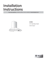
UVC9420
UVC9480
OWNER’S MANUAL &
INSTALLATION
INSTRUCTIONS
GE is a trademark of the General Electric Company. Manufactured under trademark license.
ESPAÑOL
Para consultar una version en
español de este manual de
instrucciones, visite nuestro sitio de
internet GEAppliances.com.
FRANÇAIS
Pour une version français de
ce manuel d’utilisation, veuillez
visiter notre site web à l’adresse
GEAppliances.com.

249-2000930 Rev. 2
THANK YOU FOR MAKING GE APPLIANCES A PART OF YOUR HOME.
Whether you grew up with GE Appliances, or this is your first, we’re happy to have you in the family.
We take pride in the craftsmanship, innovation and design that goes into every GE Appliances
product, and we think you will too. Among other things, registration of your appliance ensures that we
can deliver important product information and warranty details when you need them.
Register your GE appliance now online. Helpful websites and phone numbers are available in the
Consumer Support section of this Owner’s Manual. You may also mail in the pre-printed registration
card included in the packing material.

49-2000930 Rev. 2 3
SAFETY INFORMATION
IMPORTANT SAFETY INFORMATION
READ ALL INSTRUCTIONS BEFORE USING
READ AND SAVE THESE INSTRUCTIONS
WARNING TO REDUCE THE RISK OF FIRE,
ELECTRIC SHOCK OR INJURY TO PERSONS,
OBSERVE THE FOLLOWING:
A. Use this unit only in the manner intended by the
manufacturer. If you have questions, contact the
manufacturer.
B. Before servicing or cleaning unit, switch power off
at service panel and lock the service disconnecting
means to prevent power from being switched
on accidentally. When the service disconnecting
means cannot be locked, securely fasten a
prominent warning device, such as a tag, to the
service panel.
C. Do not use this unit with any solid-state speed
control device.
D. This unit must be grounded.
CAUTION FOR GENERAL VENTILATING USE
ONLY. DO NOT USE TO EXHAUST HAZARDOUS
OR EXPLOSIVE MATERIALS AND VAPORS.
CAUTION TO REDUCE RISK OF FIRE AND
TO PROPERLY EXHAUST AIR, BE SURE TO DUCT
AIR OUTSIDE. DO NOT VENT EXHAUST AIR INTO
SPACES WITHIN WALLS OR CEILINGS OR INTO
ATTICS, CRAWL SPACES OR GARAGES.
WARNING TO REDUCE THE RISK OF INJURY
TO PERSONS IN THE EVENT OF A RANGE TOP
GREASE FIRE, OBSERVE THE FOLLOWING*:
A. SMOTHER FLAMES with a close-fitting lid, cookie
sheet or metal tray, then turn off the burner. BE
CAREFUL TO PREVENT BURNS. If the flames do
not go out immediately, EVACUATE AND CALL
THE FIRE DEPARTMENT.
B. NEVER PICK UP A FLAMING PAN—You may be
burned.
C. DO NOT USE WATER, including wet dishcloths or
towels—a violent steam explosion will result.
D. Use an extinguisher ONLY if:
1. You know you have a Class ABC extinguisher,
and you already know how to operate it.
2. The fire is small and contained in the area where
it started.
3. The fire department is being called.
4. You can fight the fire with your back to an exit.
* Based on “Kitchen Fire Safety” published by NFPA.

449-2000930 Rev. 2
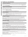
How to Remove Packaging Tape
To assure no damage is done to the finish of the
product, the safest way to remove the adhesive from
packaging tape on new appliances is an application of
a household liquid dishwashing detergent. Apply with a
soft cloth and allow to soak.
NOTE: The adhesive must be removed from all parts.
NOTE: For further cleaning instructions/suggestions,
please refer to the Care and Cleaning section.
Consider recycling options for your appliance packaging
material.
SAFETY INFORMATION
IMPORTANT SAFETY INFORMATION
READ ALL INSTRUCTIONS BEFORE USING
READ AND SAVE THESE INSTRUCTIONS
WARNING TO REDUCE THE RISK OF A
RANGE TOP GREASE FIRE:
A. Never leave surface units unattended at high
settings. Boilovers cause smoking and greasy
spillovers that may ignite. Heat oils slowly on
medium settings.
B. Always turn hood ON when cooking at high heat or
when flambéing food (i.e. Crepes Suzette, Cherries
Jubilee, Peppercorn Beef Flambé).
C. Clean ventilating fans frequently. Grease should not
be allowed to accumulate on fan or filter.
D. Use proper pan size. Always use cookware
appropriate for the size of the surface element.
WARNING TO REDUCE THE RISK OF FIRE,
ELECTRIC SHOCK OR INJURY TO PERSONS,
OBSERVE THE FOLLOWING:
A. Installation work and electrical wiring must be
done by qualified person(s) in accordance with all
applicable codes and standards, including fire-rated
construction.
B. Sufficient air is needed for proper combustion and
exhausting of gases through the flue (chimney) of
fuel burning equipment to prevent back drafting.
Follow the heating equipment manufacturer’s
guidelines and safety standards such as those
published by the National Fire Protection
Association (NFPA), the American Society for
Heating, Refrigeration and Air Conditioning
Engineers (ASHRAE) and the local code authorities.
C. When cutting or drilling into wall or ceiling, do not
damage electrical wiring and other hidden utilities.
D. Ducted fans must always be vented to the outdoors.
E. When applicable, install any makeup (replacement)
air system in accordance with local building
code requirements. Visit GEAppliances.com for
available makeup air solutions.
F. Turn off breaker to adjacent rooms while working.
WARNING TO REDUCE THE RISK OF FIRE,
USE ONLY METAL DUCTWORK.
Ŷ'RQRWDWWHPSWWRUHSDLURUUHSODFHDQ\SDUWRI\RXU
hood unless it is specifically recommended in this
manual. All other servicing should be referred to a
qualified technician.
PROPER DISPOSAL OF YOUR APPLIANCE
Dispose of or recycle your appliance in accordance with Federal and Local Regulations. Contact your local
authorities for the environmentally safe disposal or recycling of your appliance.
WARNING Disconnect all electrical power at
the main circuit breaker or fuse box before installing.
WARNING USE ONLY WITH RANGE HOOD
CORD CONNECTION KITS THAT HAVE BEEN
INVESTIGATED AND FOUND ACCEPTABLE FOR
USE WITH THIS MODEL RANGE HOOD.

49-2000930 Rev. 2 5
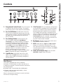
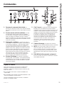
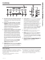
Controls
USING THE HOOD: Controls
1. Rangehood Control Panel: The control panel
is located on the front of the canopy. The position
and function of each control button are noted below.
2. Fan On/Off Button: On/Off switch for the fan.
The fan can be operated by pressing any of the fan
setting buttons. Hold for 3 seconds to activate Delay
Off feature, which automatically turns the fan off
after 15 minutes.
3. Fan Setting Button: Speed control for the
fan. Fan speed is powered by QuietBoost™
Technology. This unique technology is designed
to minimize ventilation noise and enhance motor
efficiency for a peacefully-quiet, odor-free kitchen.
Press LOW for LOW speed, MED for MEDIUM
speed, and HIGH for HIGH speed. Press and hold
the HIGH button for 3 seconds to activate the
BOOST speed that will run for 10 minutes.
On Remote, press Up to increase fan speed, press
Down to decrease fan speed, including Boost.
4. Light Button: On/Dim/Off switch for the LED
lights. Press the Light button to turn the lights on,
again to set the lights to dim setting, and again to
turn the lights off.
5. Chef Connect: This is a Bluetooth® pairing feature
for use with other compatible Chef Connect enabled
products on a cooktop or range. When the device is
paired, the light and fan will turn ON at the Default
Sync Settings upon receiving a command from the
range or cooktop. It will remain ON at that setting until
the user changes it. To pair devices, hold down the
Chef Connect button for 3 seconds. To turn it back
off, hold the button down for another 3 seconds, see
the Chef Connect section for details.
6. IR Sensor: Remote control reciever when used
with Remote Control Kit (UXRC1).
7. Wi-Fi: Hold down the Light and Chef Connect
buttons for 3 seconds to activate the Wi-Fi. The
Wi-Fi light turns on when connected
, see the Wi-Fi
Connect section for details
. On Remote, press Wi-Fi
to toggle Wi-Fi function.
8. Delay Off (Remote only): Press and hold
Delay Off to toggle Delay Off function.
Heat Sensor
Your hood is equipped with a HEAT SENSOR
thermostat. This thermostat is a device that will turn on
or speed up the blower if it senses excessive heat above
the cooking surface.
Ŷ,IEORZHULV2IILWWXUQVEORZHU2QWR0HGVSHHG
Ŷ,IEORZHULV2QDWDORZHUVSHHGVHWWLQJLWWXUQV
blower up to Med speed.
When the temperature level drops to normal, the blower
will return to its original setting.
326541
7
8
Remote Control
4
7
2
5
3

649-2000930 Rev. 2
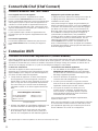
USING THE HOOD: Chef Connect / Wi-Fi Connect
Chef Connect Operation Bluetooth® Connection
To pair with another device:
To start the pairing process on the hood, press and hold
the Chef Connect button for 3 seconds. The backlight
for the Low-Med-High-Light-Chef Connect buttons will
flash in that sequence until the hood is paired with the
range or other device. If the pairing is successful, all five
backlights (Low, Med, High, Light, Chef Connect) will
flash simultaneously three times and then turn off and
the backlight for the Chef Connect button will turn on.
It will time out after 2 minutes if the pairing is not
completed, after which the pairing sequence will need to
be restarted.
To cancel pairing:
To cancel the pairing, hold the Chef Connect button
down for 3 seconds and then turn off the hood.
Default Sync Settings:
The factory default setting for the light will be the
brightest.
The factory default setting for the fan sync will be OFF.
The user can change the Default Sync Settings by
pressing and holding the Low button for 3 seconds. This
will enter the Default Settings Mode. Once in this mode,
the backlights for all buttons (Low, Med, High, Light,
Chef Connect) will blink On/Off indefinitely and the fan
and light will switch to the current Default Sync Setting,
so the user knows what the current default value is.
At this time, set the light and fan to the desired default
levels. Once the user is satisfied with the selection,
press and hold the On/Off button for 3 seconds. This
will exit this mode. At that time the backlights will stop
blinking and the state of the fan and light will change
back to their prior state before entering the Default
Settings Mode.
Chef Connect
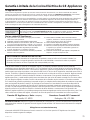
* Compatible Apple or Android devices and home Wi-Fi network required.
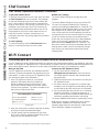
Connecting your Wi-Fi Connect Enabled hood (on some models)
Your GE Appliances hood is designed to provide you with two-way communication between your appliance and smart
device. By using the GE Appliances Wi-Fi Connect features, you will be able to control essential hood operations such
as fan speed, light functions, timer/clock function, delay off and filter reset using your smartphone or tablet.*
What you will need
Your GE Appliances hood uses your existing home Wi-Fi
network to communicate between the appliance and your
smart device. In order to setup your GE Appliances hood,
you will need to gather some information:
1. Each GE Appliances hood has a connected
appliance information label that includes an
Appliance Network Name and Password. These
are the two important details that you will need to
connect to the appliance. The label is located on the
side of the unit behind the filters.
2. Have your smart phone or tablet ready with the ability
to access the internet and download apps.
3. You will need to know the password of your home
Wi-Fi router. Have this password ready while you are
setting up your GE Appliances hood.
Connect your GE Appliances hood
1. On your smart phone or tablet visit
GEAppliances.com/connect to learn more about
connected appliance features and to download the
appropriate app.
2. Follow the app onscreen instructions to connect your
GE Appliances hood.
3. Once the process is complete, the connection light
located on your GE Appliances hood display will stay
on solid and the app will confirm you are connected.
4. If the connection light does not turn on or is blinking,
follow the instructions on the app to reconnect. If
issues continue please call 800.220.6899 and ask for
assistance regarding hood wireless connectivity.
To connect additional smart devices, repeat steps 1 and 2.
Note that any changes or modifications to the remote
enable device installed on this hood that are not
expressly approved by the manufacturer could void the
user’s authority to operate the equipment.
Wi-Fi Connect
Sample Label
Connected Appliance Information
FCC ID: ZKJ-WCATA005
IC: 10229A-WCATA001
MAC ID: ************
Network: ************
Password: **********

49-2000930 Rev. 2 7
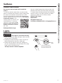
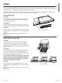
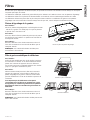
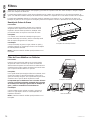
Lights
CAUTION Allow lights to cool before touching.
1. Before attempting to replace the lights, make sure that
the light switch is turned off.
2. Rotate light counterclockwise to unlock and pull out.
Wearing latex gloves may offer a better grip.
3. Replace with new light of same type, making sure
pins are inserted properly into the sockets of the lamp
holder and turn clockwise to lock.
All lamps need to be GU10 compatible.
Surfaces
CARE AND CLEANING: Surfaces / Lights
Rotate the lamp until the
pins are located in narrow
neck of the socket to lock.
Lamp
Holder
Stainless Steel Surfaces
Do not use a steel wool pad; it will scratch the
surface.
To clean the stainless steel surface, use warm sudsy
water or a stainless steel cleaner or polish. Always wipe
the surface in the direction of the brush line. Follow
the cleaner instructions for cleaning the stainless steel
surface. Cleaners with oxalic acid such as Bar Keepers
Friend Soft Cleanser™ will
remove surface rust, tarnish, and
small blemishes. To receive a
coupon for a trial sample of Bar
Keepers Friend Soft Cleanser™
follow the link below or scan the
QR Code.
barkeepersfriend.com/ge
Use only a liquid cleanser free of grit and rub in the
direction of the brush lines with a damp soft sponge.
To inquire about purchasing stainless steel appliance
cleaner or polish, or to find the location of a dealer
nearest you, please call our toll-free number:
National Parts Center
800.626.2002
GEApplianceParts.com
In Canada, call 800.661.1616 or visit geappliances.ca

849-2000930 Rev. 2
Installation
Instructions
If you have questions, call GE Appliances at 800.GE.CARES (800.432.2737)
or visit our website at: GEAppliances.com. In Canada, visit GEAppliances.ca or call 800.561.3344.
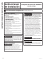
INSTALLATION INSTRUCTIONS
BEFORE YOU BEGIN
Read these instructions completely and
carefully.
Ŷ IMPORTANT — Save these
instructions for local inspector’s use.
Ŷ IMPORTANT — Observe all governing
codes and ordinances.
Ŷ Note to Installer – Be sure to leave these
instructions with the Consumer.
Ŷ Note to Consumer – Keep these instructions for
future reference.
Ŷ Skill level – Installation of this vent hood requires
basic mechanical and electrical skills.
Ŷ Completion time – Approximately 1 to 3 hours
Ŷ Proper installation is the responsibility of the
installer.
Ŷ Product failure due to improper installation is not
covered under the Warranty.
FOR YOUR SAFETY
WARNING Before beginning the installation,
switch power off at service panel and lock the
service disconnecting means to prevent power from
being switched on accidentally. When the service
disconnecting means cannot be locked, securely
fasten a prominent warning device, such as a tag, to
the service panel.
CAUTION Due to the weight and size of these
vent hoods and to reduce the risk of personal injury
or damage to the product, TWO PEOPLE ARE
REQUIRED FOR PROPER INSTALLATION.
WARNING Disconnect all electrical power at
the main circuit breaker or fuse box before installing.
WARNING TO REDUCE THE RISK OF FIRE,
ELECTRIC SHOCK OR INJURY TO PERSONS,
OBSERVE THE FOLLOWING:
A. Installation work and electrical wiring must be
done by qualified person(s) in accordance with
all applicable codes and standards, including
fire-rated construction.
B. Sufficient air is needed for proper combustion
and exhausting of gases through the flue
(chimney) of fuel burning equipment to prevent
back drafting. Follow the heating equipment
manufacturer’s guidelines and safety standards
such as those published by the National Fire
Protection Association (NFPA), the American
Society for Heating, Refrigeration and Air
Conditioning Engineers (ASHRAE) and the local
code authorities.
C. When cutting or drilling into wall or ceiling, do
not damage electrical wiring and other hidden
utilities.
D. Ducted fans must always be vented to the
outdoors.
E. Turn off breaker to adjacent rooms while working.
WARNING TO REDUCE THE RISK OF FIRE,
USE ONLY METAL DUCT WORK.
Custom Insert Hood
UVC9420, UVC9480

49-2000930 Rev. 2 9
Installation Preparation
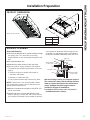
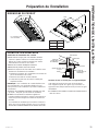
PRODUCT DIMENSIONS
INSTALLATION PREPARATION
Design varies by model
15"
12 1/2"
A"
21 7/8"
7 5/8"
28 7/16"
Model A
UVC9420 39-1/2"
UVC9480 45-3/4"
ADVANCE PLANNING
Duct Install Planning
Ŷ7KLVKRRGLVGHVLJQHGWREHYHQWHGYHUWLFDOO\WKURXJK
the ceiling. Use a 10" round duct. Use locally
supplied elbows to vent horizontally through the rear
wall.
Ŷ8VHPHWDOGXFWZRUNRQO\
Ŷ'HWHUPLQHWKHH[DFWORFDWLRQRIWKHYHQWKRRG
ŶPlan the route for venting exhaust to the outdoors.
To maximize the ventilation performance of the vent
system:
1. Minimize the duct run length and number of
transitions and elbows.
2. Maintain a constant duct size.
3. Seal all joints with duct tape to prevent any leaks.
NOTE: Flexible vent is not recommended. Flexible
vent creates back pressure and air turbulence that
greatly reduces performance.
Ŷ0D[LPXPHTXLYDOHQWGXFWOHQJWKIRU&)0
foot for vent hoods.
Ŷ,QVWDOODZDOOFDSRUURRIFDSZLWKGDPSHUDWWKH
exterior opening. Purchase the wall or roof cap and
any transition and length of duct needed in advance.
Vent system can terminate either through the roof
RUWKHZDOO7RYHQWWKURXJKDZDOODHOERZLV
needed and installed immediately above the hood.
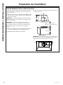
Wall and Ceiling Framing for Adequate Support
This vent hood is heavy and the cabinet structure
needs to support the weight of the loaded insert
sleeve. Adequate structural support must be
provided in all types of installations.
Ŷ,QVWDOODWLRQZLOOEHHDVLHULIWKHYHQWKRRGLV
installed before the cooktop.
Roof Cap
Round Duct
Wall Cap
Add Insulation
and/or Caulk
Add Insulation
and/or Caulk
Cabinet
Add tape to joint
Hood

10 49-2000930 Rev. 2
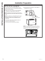
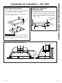
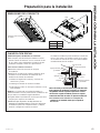
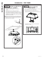
INSTALLATION CLEARANCES
This vent hood must be installed between the 30"
required minimum and 36" recommended maximum
above the cooking surface.
Ŷ$OZD\VUHIHUWRWKHFRRNWRSRUUDQJHLQVWDOODWLRQ
instructions for product-specific clearances.
NOTE: Installation height should be measured from
the cooking surface to the bottom edge of the cabinet
surface.
NOTE: UL requires any combustible surface to be a
minimum of 30" above the cooking surface. Lower
combustible surfaces may be covered to meet
requirements.
Ŷ7KHFXVWRPFDELQHWLQWHUQDOKHLJKWPXVWEH
minimum for vertical venting.
Ŷ7KLVKRRGPXVWEHYHQWHGWRWKHRXWGRRUV
Ŷ7KLVKRRGPD\EHPRXQWHGLQDZDOOFDELQHWRU
installed over an island.
NOTE: The exhaust duct on the hood is closer to
the rear of the hood. It is important to plan for the
alignment to the connection point of the hood.
*30" Minimum required
*36" Maximum recommended
Typically 36"
17" min. 12-1/2"
7-5/8"
Installation Preparation
INSTALLATION PREPARATION

49-2000930 Rev. 2 11
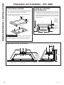
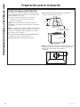
INSTALLATION PREPARATION
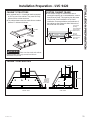
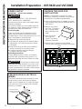
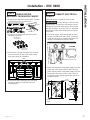
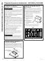
Installation Preparation - UVC 9420
CABINET PREPARATION
C
LC
L
7-5/8”
18-1/2” Min.
15”
FRONT VIEW SIDE VIEW
CABINET STRUCTURE
Ŷ
It is required two 2 x 4 horizontal studs separated
by 39” as part of the cabinet. They must be firmly
secured to the cabinet structure.
Ŷ
The cabinet bottom must be made from a wooden
surface ¾” minimum thickness.
WARNING Make sure the studs and cabinet
bottom surface are firmly secured and able to
withstand 100 pounds.
2" Min.
2" Min.
39" Between
Studs
CUSTOM CABINET FRAME
ŶThe custom canopy or cabinet must have a
rectangular opening to accommodate the custom
hood insert by itself. This opening has the same
size for both a wall installation or an island
installation. Ensure parallelism and levelness of
the cabinet so that it doesn't affect flushness of
the hood with the cabinet.
39"
Front of the
opening
recommended
to be 3” from
cabinet front
Back of
opening
recommended
to be 3” from
back wall
21-1/4"
13" from
bottom of
cabinet to
bottom of
house duct

12 49-2000930 Rev. 2
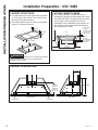
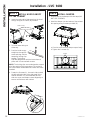
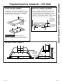
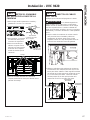
Installation Preparation - UVC 9480
CABINET PREPARATION
C
LC
L
7-5/8”
18-1/2” Min.
15”
FRONT VIEW SIDE VIEW
Side Panel Side Panel
CABINET STRUCTURE
Ŷ
It is required two 2 x 4 horizontal studs separated
by 39” as part of the cabinet. They must be firmly
secured to the cabinet structure.
Ŷ
The cabinet bottom must be made from a wooden
surface ¾” minimum thickness.
WARNING Make sure the studs and cabinet
bottom surface are firmly secured and able to
withstand 100 pounds.
C
L
2" Min.
2" Min.
39" Between
Studs
CUSTOM CABINET FRAME
ŶThe custom canopy or cabinet must have a
rectangular opening to accommodate the custom
hood insert by itself. This opening has the same
size for both a wall installation or an island
installation. Ensure parallelism and levelness of
the cabinet so that it doesn't affect flushness of
the hood with the cabinet.
C
L
Front of the
opening
recommended
to be 3” from
cabinet front
Back of
opening
recommended
to be 3” from
back wall
21-1/4"
39"
between studs
45"
cutout width
13" from
bottom of
cabinet to
bottom of
house duct
INSTALLATION PREPARATION

49-2000930 Rev. 2 13
INSTALLATION PREPARATION
PLAN THE INSTALLATION
CAUTION To reduce risk of fire and to
properly exhaust air, be sure to duct the air
outside – Do not vent exhaust air into spaces
within walls or ceilings or into attics, crawl
spaces, or garages.
WARNING
PERSONAL INJURY HAZARD
It is recommended that 2 people are used to
install the range hood. Failure to properly
lift rangehood could result in damage to the
product or personal injury.
REMOVE THE PACKAGING
CAUTION Wear gloves to protect against
sharp edges.
Ŷ Remove the hardware bag, literature package
and other boxed parts.
Ŷ Remove and properly discard the protective
plastic wrapping and other packaging materials.
Ŷ Consider recycling options for your appliance
packaging material.
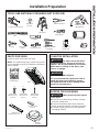
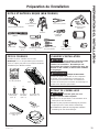
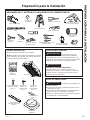
TOOLS AND MATERIALS REQUIRED (NOT SUPPLIED)
Pencil and tape measure
Step ladder
Phillips and flat-blade
screwdrivers
Level Safety glasses
10" ducting and
caps as needed
Aluminized
duct tape Electric drill and
appropriate bits
Gloves
Flashlight
Needle-nose pliers
Tin snips Wire cutter/
stripper Strain relief for
junction box
UL listed wire nuts
PARTS PROVIDED
Locate the parts packed with the hood.
NOTE: The hardware bag may contain extra pieces
to accommodate a variety of installation methods for
various models.
Damper
Assembly
Remote Control
(QTY: 1)
Hardware Bag
Philips Head
Machine Screw
(QTY: 8)
Phillips Head
Wood Screws
(QTY: 2)
Side Panel
UVC9480 only (QTY: 2)
B D
Hood
Phillips Head
Wood Screws
(QTY: 8)
L
Installation Preparation

14 49-2000930 Rev. 2
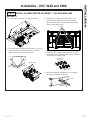
Installation Preparation - UVC9420 and UVC9480
POWER SUPPLY
IMPORTANT – (Please read carefully)
WARNING
FOR PERSONAL SAFETY, THIS APPLIANCE
MUST BE PROPERLY GROUNDED.
Remove house fuse or open circuit breaker before
beginning installation.
Do not use an extension cord or adapter plug with
this appliance. Follow National Electrical Codes or
prevailing local codes and ordinances.
Electrical supply
These vent hoods must be supplied with 120V,
60Hz, and connected to an individual, properly
grounded branch circuit, and protected by a 15 or 20
amp circuit breaker or time delay fuse.
ŶWiring must be 2 wire with ground.
ŶIf the electrical supply does not meet the above
requirements, call a licensed electrician before
proceeding.
ŶRoute house wiring as close to the installation
location as possible in the ceiling or wall.
ŶConnect the wiring to the house wiring in
accordance with local codes.
Grounding instructions
The grounding conductor must be connected to
a ground metal, permanent wiring system, or an
equipment-grounding terminal or lead on the hood.
WARNING The improper connection of the
equipment-grounding conductor can result in a risk
of electric shock. Check with a qualified electrician
or service representative if you are in doubt whether
the appliance is properly grounded.
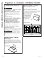
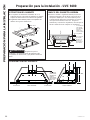
PREPARE HOUSE ELECTRICAL
WIRING
The custom cabinet must allow spacing for house
wiring to reach junction box located in diagram
below. If unit is installed over an island, the wiring
must come from ceiling. If power cord is needed,
accessory is available.
PREPARE THE HOOD FOR
INSTALLATION
NOTE: For transportation purposes the motor
assembly is secured by 2 brackets. They must be
removed prior to installation and discarded.
ŶPlace insert hood canopy on padded, yet stable,
surface below cutout (can use flattened carton to
pad surface).
ŶRemove the junction
box cover. The junction
box is located inside
the top left side of the
hood.
ŶSave the junction
box cover and
screws. They will be
needed at installation.
ŶRemove the 12 screws from the brackets
over the motor assembly to remove the brackets.
The junction box is
located in this area
inside the hood. Electrical
Area
24"
Brackets
Screws
INSTALLATION PREPARATION

49-2000930 Rev. 2 15
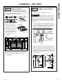
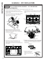
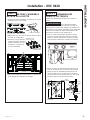
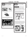
Installation - UVC 9420
STEP 1 REMOVE MOTOR
ASSEMBLY FROM HOOD CANOPY
1. Remove the metal lid by removing the 3 screws
and allowing access to connectors.
2. Disconnect 2 motor
cable connectors and 2
capacitor connectors.
3. Remove the 4 screws
that attach the common
motor bracket to the
top of the hood canopy.
Save the screws for
installation.
4. Remove the motor assembly from the hood
canopy by sliding it to release it from the
mounting tabs.
Screws
STEP 2 CONNECT ELECTRICAL
CABLES
Verify that power is turned off at the source.
WARNING If house wiring is not 2-wire with
a ground wire, an electrician will need to convert
existing wiring to meet these specs. When house
wiring is aluminum, be sure to use U.L.-approved
anti-oxidant compound and aluminum-to-copper
connectors.
1. Pull power supply wires through wall of insert
canopy and attach the strain relief. Thread the
house wire through the junction box before the
canopy is inserted in the cabinet cutout.
2.
Attach the white lead of the power supply (A) to the
white lead of the range hood (D) with a wire nut.
Attach the black lead of the power supply (B) to the
black lead of the range hood (C) with a wire nut.
Connect the power supply ground wire lead (E) to
the ground screw.
Strain
Relief
Hood
Wiring
AA
D
D
E
E
BB
C
C
Power
Supply
Strain
Relief Strain
Relief
INSTALLATION
Wires
Metal Lid
Screws
Connectors on
Hood Side
Connectors on
Motor Side

16 49-2000930 Rev. 2
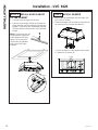
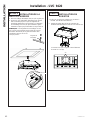
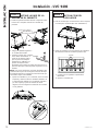
STEP 3 INSTALL HOOD CANOPY
TO THE CABINET
1. Tuck the house wiring out of the way.
2. Push the hood canopy straight up through the
cutout opening until the temporary locking clips
engage. The locking clips are designed to hold
the insert sleeve in place until it is secured with
screws.
NOTE: The locking clips are
not designed to support all
of the weight of the insert
sleeve. Do not leave the
insert sleeve unattended
until screws have been
installed.
STEP 4 INSTALL DAMPER
1. Seal the duct to the damper with duct tape. (DO
NOT USE SCREWS)
2. Install the damper into the bottom of the exhaust
fan opening using 2 screws provided (D).
a. Check to make sure the damper opens freely.
b. Tighten the 2 screws (D).
Installation - UVC 9420
2x4 Stud
Screws
Clip
INSTALLATION

49-2000930 Rev. 2 17
INSTALLATION
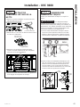
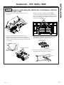
Installation - UVC 9480
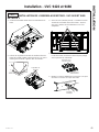
STEP 1 REMOVE MOTOR
ASSEMBLY FROM HOOD CANOPY
1. Remove the metal lid by removing the 3 screws
and allowing access to connectors.
2. Disconnect 2 motor cable connectors and 2
capacitor connectors.
3. Remove the 4 screws that attach the common
motor bracket to the top of the hood canopy.
Save the screws for installation.
4. Remove the motor assembly from the hood
canopy by sliding it to release it from the
mounting tabs.
Screws
Metal Lid
Screws
Connectors on
Hood Side
Connectors on
Motor Side
STEP 2 CONNECT ELECTRICAL
CABLES
Verify that power is turned off at the source.
WARNING If house wiring is not 2-wire with
a ground wire, an electrician will need to convert
existing wiring to meet these specs. When house
wiring is aluminum, be sure to use U.L.-approved
anti-oxidant compound and aluminum-to-copper
connectors.
1. Pull power supply wires through wall of insert
canopy and attach the strain relief. Thread the
house wire through the junction box before the
canopy is inserted in the cabinet cutout.
2.
Attach the white lead of the power supply (A) to the
white lead of the range hood (D) with a wire nut.
Attach the black lead of the power supply (B) to the
black lead of the range hood (C) with a wire nut.
Connect the power supply ground wire lead (E) to
the ground screw.
Strain
Relief
Hood
Wiring
AA
D
D
E
E
BB
C
C
Power
Supply
Strain
Relief Strain
Relief
Wires

18 49-2000930 Rev. 2
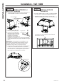
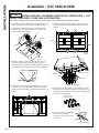
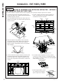
STEP 3 INSTALL HOOD CANOPY
TO THE CABINET
1. Install the right and left side panels to the hood
canopy using the 4 screws (B) provided.
2. Tuck the house wiring out
of the way.
3. Push the hood canopy
straight up through the
cutout opening until the
temporary locking clips
engage. The locking
clips are designed to hold the insert sleeve in
place until it is secured with screws.
NOTE: The locking clips are not designed to support
all of the weight of the insert sleeve. Do not leave
the insert sleeve unattended until screws have been
installed.
4. Fasten the 8 screws (L), 4 on each side, toward
the left and right sides to the side studs of the
cabinet structure. It is recommended to start
with one corner and fasten screws diagonally to
ensure unit flushness with cabinet.
Installation - UVC 9480
STEP 4 INSTALL DAMPER
1. Seal the duct to the damper with duct tape (DO
NOT USE SCREWS).
2. Install the damper into the bottom of the exhaust
fan opening using 2 screws provided (D).
a. Check to make sure the damper opens freely.
b. Tighten the 2 screws (D).
Screws
Side Panel (1 per side)
Hood Canopy
Clip
2x4 Stud
INSTALLATION

49-2000930 Rev. 2 19
INSTALLATION
STEP 5 INSTALL BLOWER MOTOR ASSEMBLY - UVC-9420 AND 9480
METHOD 1
1. Lift the motor assembly on the insert canopy.
2. Insert the blower motor assembly tabs in the hood
slots and slide it, such that the motor assembly
slides from right to left into the 4 slots.
3. Tighten the 4 screws (removed earlier) - see
Remove Motor Assembly from Hood Canopy
section. Make sure the blower motor is secured
firmly to the hood canopy.
4. Reconnect the 4 cables of the motor to the ones
on the hood side and insert them into the protected
area under the control panel.
5. Mount the metal lid and tighten the 3 screws to
secure the lid on the hood body.
Installation - UVC 9420 and 9480
Slots on Hood
Mounting Tabs
Screws
Metal Lid
Screws
Connectors on
Hood Side
Connectors on
Motor Side

20 49-2000930 Rev. 2
STEP 5 INSTALL BLOWER MOTOR ASSEMBLY - UVC 9420 AND 9480
METHOD 2 (ALTERNATIVE)
The motors can also be installed separately to help manage the weight of the 2 motors.
1. See see Remove Motor Assembly from Hood
Canopy section to disassemble the motor assembly
from the canopy.
2. With the motor assembly out of the canopy, remove
the 4 screws from each motor. The motors are
separate from the motor plate.
3. Mount the hood into the cabinet as shown in
previous instructions. Mount the motor plate,
inserting it in the hood slots. Slide it, making sure
the 4 tabs are engaged.
4. Reinstall the 4 screws removed earlier. See
Remove Motor Assembly from Hood Canopy
section. Make sure the plate is secured firmly to the
hood canopy.
5. Lift and attach each motor using 4 screws per motor
making sure they are firmly attached to the motor
plate.
6. With both motors installed on canopy, reconnect the
4 cables of the motor to the ones on the hood side
and insert them into the protected area under the
control panel.
7. Mount the metal lid and
tighten the 3 screws to
secure the lid on the hood
body.
Slots on Hood
Installation - UVC 9420 and 9480
Motor 1
Motor 2
Screws Screws
Screws Screws Motor
Plate
Screws
Motor
Screws
Motor
Plate
Motor
Motor 1
Motor 2
Motor Plate
Screws
Metal Lid
Screws
Connectors on
Hood Side
Connectors on
Motor Side
INSTALLATION
La page est en cours de chargement...
La page est en cours de chargement...
La page est en cours de chargement...
La page est en cours de chargement...
La page est en cours de chargement...
La page est en cours de chargement...
La page est en cours de chargement...
La page est en cours de chargement...
La page est en cours de chargement...
La page est en cours de chargement...
La page est en cours de chargement...
La page est en cours de chargement...
La page est en cours de chargement...
La page est en cours de chargement...
La page est en cours de chargement...
La page est en cours de chargement...
La page est en cours de chargement...
La page est en cours de chargement...
La page est en cours de chargement...
La page est en cours de chargement...
La page est en cours de chargement...
La page est en cours de chargement...
La page est en cours de chargement...
La page est en cours de chargement...
La page est en cours de chargement...
La page est en cours de chargement...
La page est en cours de chargement...
La page est en cours de chargement...
La page est en cours de chargement...
La page est en cours de chargement...
La page est en cours de chargement...
La page est en cours de chargement...
La page est en cours de chargement...
La page est en cours de chargement...
La page est en cours de chargement...
La page est en cours de chargement...
La page est en cours de chargement...
La page est en cours de chargement...
La page est en cours de chargement...
La page est en cours de chargement...
La page est en cours de chargement...
La page est en cours de chargement...
La page est en cours de chargement...
La page est en cours de chargement...
La page est en cours de chargement...
La page est en cours de chargement...
La page est en cours de chargement...
La page est en cours de chargement...
La page est en cours de chargement...
La page est en cours de chargement...
La page est en cours de chargement...
La page est en cours de chargement...
La page est en cours de chargement...
La page est en cours de chargement...
La page est en cours de chargement...
La page est en cours de chargement...
La page est en cours de chargement...
La page est en cours de chargement...
-
 1
1
-
 2
2
-
 3
3
-
 4
4
-
 5
5
-
 6
6
-
 7
7
-
 8
8
-
 9
9
-
 10
10
-
 11
11
-
 12
12
-
 13
13
-
 14
14
-
 15
15
-
 16
16
-
 17
17
-
 18
18
-
 19
19
-
 20
20
-
 21
21
-
 22
22
-
 23
23
-
 24
24
-
 25
25
-
 26
26
-
 27
27
-
 28
28
-
 29
29
-
 30
30
-
 31
31
-
 32
32
-
 33
33
-
 34
34
-
 35
35
-
 36
36
-
 37
37
-
 38
38
-
 39
39
-
 40
40
-
 41
41
-
 42
42
-
 43
43
-
 44
44
-
 45
45
-
 46
46
-
 47
47
-
 48
48
-
 49
49
-
 50
50
-
 51
51
-
 52
52
-
 53
53
-
 54
54
-
 55
55
-
 56
56
-
 57
57
-
 58
58
-
 59
59
-
 60
60
-
 61
61
-
 62
62
-
 63
63
-
 64
64
-
 65
65
-
 66
66
-
 67
67
-
 68
68
-
 69
69
-
 70
70
-
 71
71
-
 72
72
-
 73
73
-
 74
74
-
 75
75
-
 76
76
-
 77
77
-
 78
78


GE Profile UVC9420SLSS Le manuel du propriétaire
- Catégorie
- Hottes
- Taper
- Le manuel du propriétaire
- Ce manuel convient également à
dans d''autres langues
Documents connexes
Autres documents
-
GE UVC7300SLSS Le manuel du propriétaire
-
GE UVC9360SLSS Le manuel du propriétaire
-
Monogram UVC9360SLSS Mode d'emploi
-
GE Appliances UVC9300SLSS Le manuel du propriétaire
-
GE Appliances UVC7300 Le manuel du propriétaire
-
-
-
GE Profile Series JN327HCC Le manuel du propriétaire
-
GE ZV30HSRSS Guide d'installation
-
 GE Monogram GEZV950SDSS DL 5d7bc61df13207f0d1d3b946cc81
