
Dell™ PowerEdge™
M905, M805, M710, M610,
M605, and M600 Systems
Information Update

Notes and Cautions
NOTE: A NOTE indicates important information that helps you make better use
of your computer.
CAUTION: A CAUTION indicates potential damage to hardware or loss of data
if instructions are not followed.
___________________
Information in this document is subject to change without notice.
© 2008–2009 Dell Inc. All rights reserved.
Reproduction of these materials in any manner whatsoever without the written permission of Dell Inc.
is strictly forbidden.
Trademarks used in this text: Dell, and DELL logo, PowerEdge, PowerConnect, and OpenManage are
trademarks of Dell Inc.; Microsoft, Windows, and Windows Server are either trademarks or registered
trademarks of Microsoft Corporation in the United States and/or other countries.
Other trademarks and trade names may be used in this document to refer to either the entities claiming
the marks and names or their products. Dell Inc. disclaims any proprietary interest in trademarks and
trade names other than its own.
August 2009 Rev A05

Information Update 3
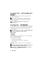
Microsoft
®
Updates
The following issues are documented on the Microsoft Help and Support
website at support.microsoft.com:
• Systems running Microsoft
®
Windows Server
®
2003 or Windows Server 2008
cannot be set into hibernation mode if they have more than 4 GB of
memory installed. For more information, see the knowledge base article
at
support.microsoft.com/kb/888575.
• Systems running Windows Server 2008 do not support iSCSI boot when
they have an SD card installed in the internal SD module. In addition,
iSCSI boot does not work when an external USB storage device is plugged
into the system. This is a known issue by Microsoft. For more information,
see the knowledge base article at
support.microsoft.com/kb/968410.
Dell Update Package Information
During the Dell Update Package (DUP) installation process you may
see messages related to the following:
NOTE: These messages are for information only.
• Windows hardware detection
• Windows hardware configuration problem
• Re-enumeration of VFlash and momentary drive letter changes in
Windows
CAUTION: It is recommended that no write operations take place (or performed)
during DUP installation on VFlash.
• Request for system reboot after the interface to the Unified Server
Configurator driver or the diagnostic repository closes
NOTE: Reboot the system only after the complete message is displayed.

4 Information Update
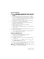
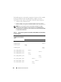
Options for Memory Power and Performance
Management
The options for memory power and performance management in the
Power Management screen are Maximum Performance, a specified
frequency, or Minimum Power.
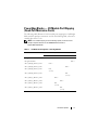
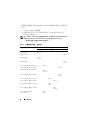
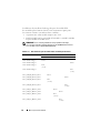
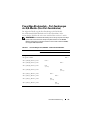
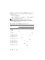
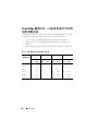
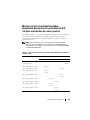
System Memory — PowerEdge M710
The following table is an addition to Table 3-5 "Examples of PowerEdge
M710 Memory Configurations" in your Hardware Owner’s Manual.
System Specifications Update
Total
Physical
Memory
Memory
Modules
– Number
and Type
Memory
Module
Locations
Processors Memory
Mode
Available
Memory
24 GB 12 2-GB
RDIMMs
A2, A3, A5,
A6, A8, A9,
B2, B3, B5,
B6, B8, B9
Two Advanced
ECC
24 GB
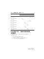
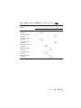
Memory — Dell™ PowerEdge™ M905 and Dell PowerEdge M805
Architecture DDR2 memory modules, rated for 800–MHz
operation

Information Update 5
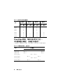
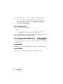
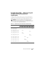
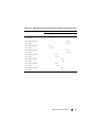
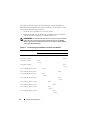
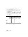
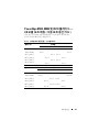
PowerEdge Blades — I/O Module Port Mapping
(Quad-Port Mezzanine Cards)
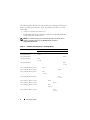
The following table illustrates the I/O module port mapping for a half-height
blade with the quad-port mezzanine card. In the following table, n denotes a
variable value from 1 to 16.
NOTE: For a detailed mapping of each PowerEdge system, see the document
Quadport Capable Hardware For the M1000e Modular Chassis on
support.dell.com/manuals.
Table 1-1. I/O Module Port Assignments—Half-Height Blades
Blade n I/O Module
A1 B1 C1 C2 B2 A2
Integrated LOM1 Port n
Integrated LOM2 Port n
Mezz_FAB_B_Blade n_Port1 Port n
Mezz_FAB_B_Blade n_Port2 Port n
Mezz_FAB_B_Blade n_Port3 Port
(n+16)
Mezz_FAB_B_Blade n_Port4 Port
(n+16)
Mezz_FAB_C_Blade n_Port1 Port n
Mezz_FAB_C_Blade n_Port2 Port n
Mezz_FAB_C_Blade n_Port3 Port
(n+16)
Mezz_FAB_C_Blade n_Port4 Port
(n+16)

6 Information Update
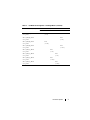
The following table illustrates the I/O module port mapping for full-height
blades with quad-port mezzanine cards. The following notations are used
in the table:
•n
denotes a variable value from 1 to 8
• LOM1 and LOM2 are the LOM ports of blade
n
and LOM3 and LOM4
are the LOM ports of blade (
n
+8)
NOTE: For a detailed mapping of each PowerEdge system, see the document
Quadport Capable Hardware For the M1000e Modular Chassis on
support.dell.com/manuals.
Table 1-2. I/O Module Port Assignments—Full-Height Blades
Blade n and Blade (n + 8) I/O Module
A1 B1 C1 C2 B2 A2
Integrated LOM1 Port n
Integrated LOM2 Port n
Integrated LOM3 Port
(n+8)
Integrated LOM4 Port
(n+8)
Mezz_FAB_B_Blade n_Port1 Port n
Mezz_FAB_B_Blade n_Port2 Port n
Mezz_FAB_B_Blade n_Port3 Port
(n+16)
Mezz_FAB_B_Blade n_Port4 Port
(n+16)
Mezz_FAB_C_Blade n_Port1 Port n
Mezz_FAB_C_Blade n_Port2 Port n
Mezz_FAB_C_Blade n_Port3 Port
(n+16)
Mezz_FAB_C_Blade n_Port4 Port
(n+16)

Information Update 7
Mezz_FAB_B_Blade
n+8_Port1
Port
(n+8)
Mezz_FAB_B_Blade
n+8_Port2
Port
(n+8)
Mezz_FAB_B_Blade
n+8_Port3
Port
(n+24)
Mezz_FAB_B_Blade
n+8_Port4
Port
(n+24)
Mezz_FAB_C_Blade
n+8_Port1
Port
(n+8)
Mezz_FAB_C_Blade
n+8_Port2
Port
(n+8)
Mezz_FAB_C_Blade
n+8_Port3
Port
(n+24)
Mezz_FAB_C_Blade
n+8_Port4
Port
(n+24)
Table 1-2. I/O Module Port Assignments—Full-Height Blades (continued)
Blade n and Blade (n + 8) I/O Module
A1 B1 C1 C2 B2 A2

8 Information Update
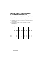
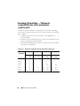
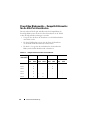
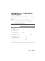
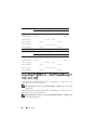
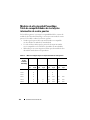
PowerEdge Blades — Compatibility Matrix
For the Quad-Port Mezzanine Cards
The following tables shows the compatibility of the PowerEdge blade systems
with the quad-port mezzanine card. The following notations are used in the
table.
•X
denotes that the mezzanine card ports are supported on the IOM fabric.
• A blank value denotes that the mezzanine card ports are not supported
on the IOM fabric.
• N/A denotes that the fabric does not exist for the corresponding
half
–
height blades.
Table 1-3. Configuration Matrix for Quad-Port Mezzanine Card
PowerEdge
Blade
Fabric B1 Fabric C1 Fabric B2 Fabric C2
Port 1
and 2
Port 3
and 4
Port 1
and 2
Port 3
and 4
Port 1
and 2
Port 3
and 4
Port 1
and 2
Port 3
and 4
M710 XXXXXXX
M905 X X X X
M805 X X X X
M605 X X N/A N/A N/A N/A
M610 X X X X N/A N/A N/A N/A
M600 X X X X N/A N/A N/A N/A

Information Update 9
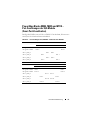
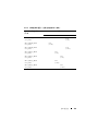
PowerEdge M905, M805, and M710 Blades —
I/O Module Port Mapping (Dual-Port Mezzanine
Cards)
The following tables correct portions of Table 1-12 in the "About Your System"
section of your Hardware Owner’s Manual.
Table 1-4. I/O Module Port Assignments—Full-Height Blades
Blade 1 I/O Module
A1 B1 C1 C2 B2 A2
Integrated LOM1 Port 1 Port 1
Integrated LOM2 Port 9 Port 9
Mezz1_Fab_C Port 1 Port 1
Mezz2_Fab_B Port 1 Port 1
Mezz3_Fab_C Port 9 Port 9
Mezz4_Fab_B Port 9 Port 9
Blade 4 I/O Module
A1 B1 C1 C2 B2 A2
Integrated LOM1 Port 4 Port 4
Integrated LOM2 Port 12 Port 12
Mezz1_Fab_C Port 4 Port 4
Mezz2_Fab_B Port 4 Port 4
Mezz3_Fab_C Port 12 Port 12
Mezz4_Fab_B Port 12 Port 12

10 Information Update
PowerEdge™ Blades — Dell™ OpenManage™
Version Requirements
The PowerEdge M905 and M805 blades require OpenManage systems
management software version 5.4.3 or later.
NOTE: OpenManage version 5.4.3 does not support PowerEdge M600 or
M605 blades.
The PowerEdge M610 and M710 blades require OpenManage systems
management software version 6.0.1 or later.
NOTE: OpenManage version 6.0.1 does not support PowerEdge M600, M605, M805,
or M905 blades.
Blade 8 I/O Module
A1 B1 C1 C2 B2 A2
Integrated LOM1 Port 8 Port 8
Integrated LOM2 Port 16 Port 16
Mezz1_Fab_C Port 8 Port 8
Mezz2_Fab_B Port 8 Port 8
Mezz3_Fab_C Port 16 Port 16
Mezz4_Fab_B Port 16 Port 16
Blade 6 I/O Module
A1 B1 C1 C2 B2 A2
Integrated LOM1 Port 6 Port 6
Integrated LOM2 Port 14 Port 14
Mezz1_Fab_C Port 6 Port 6
Mezz2_Fab_B Port 6 Port 6
Mezz3_Fab_C Port 14 Port 14
Mezz4_Fab_B Port 14 Port 14

Information Update 11
PowerEdge Blades — CMC Firmware
Requirements
PowerEdge M905 and M805 blades require CMC firmware version 1.2 or
later. PowerEdge M610 and M710 blades require CMC firmware version 2.0
or later. If you add these blades to an M1000e enclosure with an older CMC
firmware version, the new blades will not power on.
NOTE: See the latest Dell Chassis Management Controller User's Guide at
support.dell.com for complete instructions on how to configure and operate
the CMC module.
Updating the CMC Firmware
Downloading the CMC Firmware
Before beginning the firmware update, download the latest firmware version
from the support.dell.com website, and save it to your local system.
The following software components are included with your CMC firmware
package:
• Compiled CMC firmware code and data
• Web-based interface, JPEG, and other user interface data files
• Default configuration files
Use the Firmware Update page to update the CMC firmware to the latest
revision.
NOTE: See the latest Dell Chassis Management Controller User's Guide at
support.dell.com for complete instructions on how to configure and operate
the CMC module.
NOTE: The firmware update, by default, will retain the current CMC settings.
During the update process, you have the option to reset the CMC configuration
settings back to the factory default settings.

12 Information Update
Updating Firmware in a Redundant CMC Configuration
CAUTION: In a redundant CMC configuration, you must update CMC firmware on
both modules. Failure to do so may cause unexpected behavior during a CMC
failover or failback. Use the following procedure for redundant CMC deployments.
1
Locate the secondary or standby CMC by using the RACADM
getsysinfo
command, or by using the
Chassis Summary
page in the
Web-based
interface
.
The status indicator will be solid blue on the primary or active
CMC module and off on the standby or secondary CMC.
2
Update the firmware on the standby CMC first. See "Updating the CMC
Firmware Using the Web-based Interface" or "Updating the CMC
Firmware Using RACADM."
3
Verify that the secondary or standby CMC’s firmware is at the requested
level with the
getsysinfo
command or through the
Web-based interface
.
4
After the standby CMC has rebooted, update the firmware on the active
or primary CMC. Allow 10 minutes for the standby CMC to boot.
See "Updating the CMC Firmware Using the Web-based Interface"
or "Updating the CMC Firmware Using RACADM."
5
Verify that the active or primary CMC firmware is at the requested level
using the
getsysinfo
command or through the
Web-based interface
.
6
Once both CMCs are updated to the same firmware revision, use the
cmcchangeover
command to reset the CMC in the left slot as primary.
Updating the CMC Firmware Using the Web-based Interface
1
Log in to the Web-based interface. See "Logging in to the CMC Using
the Web-Based Interface" in your M1000e
Configuration Guide
.
2
Click
Chassis in the system tree
.
3
Click the
Update
tab. The
Updatable Components
page appears.
4
On the
Updatable Components
page, click the CMC name.
The
Firmware Update
page appears.

Information Update 13
5
In the
Va lu e
field, type the path on your management station or shared
network where the firmware image file resides, or click
Browse
to navigate
to the file location.
NOTE: The default CMC firmware image name is firmimg.cmc and the filename
should not be changed. Keep different firmware revisions separated as the file
name will always be the same.
6
Click
Update
. A dialog box appears asking you to confirm the action.
7
Click
Yes
to continue. The firmware transfer process will begin and the
status will display the message "Firmware Update in Progress." Once the
CMC update is complete, the CMC will be reset. Once the reset is
complete, you will need to refresh the
User Interface
page to log in again.
Updating the CMC Firmware Using RACADM
1
Open a CMC command line console and log in.
2
Ty p e :
racadm fwupdate -g -u -a <TFTP server IP address>
-d <filepath> -m <cmc-active|cmc-standby>
See the latest Dell Chassis Management Controller User's Guide at
support.dell.com for complete instructions on how to configure and operate
the CMC module.
PowerEdge M905 and M805 Blades —
Memory Sparing Requirements
The following information updates the memory sparing subsections in your
Hardware Owner’s Manual and these blades’ system information labels.
PowerEdge M905
Memory sparing is supported if 24 identical memory modules (DIMMs)
are installed.
PowerEdge M805
Memory sparing is supported if 16 identical memory modules are installed.

14 Information Update
New Mezzanine Cards
Your blade now supports the following additional mezzanine cards:
•Intel
®
Gigabit ET Quad-Port Mezzanine Card. See "Configuration Matrix
for Quad-Port Mezzanine Card" on page 8 for the support matrix.
• Broadcom NetXExtreme II 5709 Quad Port Ethernet Mezzanine Card
for M-Series Blades. See "Configuration Matrix for Quad-Port Mezzanine
Card" on page 8 for the support matrix.
• Broadcom NetXtreme II 57711 Dual Port 10 Gb Ethernet Mezzanine Card
with TOE and iSCSI Offload for M-Series Blades
• Broadcom 57710 10 Gb Ethernet card
• Emulex LPe1205-M FC8 card
• ConnectX MDI QDR
NOTE: CMC firmware version 1.3 is required to support FC8 mezzanine cards
and I/O modules.
NOTE: CMC firmware version 2.0 is required to support link tuning in mezzanine
cards.
For information on installing a mezzanine card, see "Installing System
Components" in your Hardware Owner’s Manual. For detailed information
on configuring a particular card, see the card’s documentation on
support.dell.com.
New I/O Modules
Your system now supports the following additional I/O modules:
• Dell PowerConnect™ M8024 10 Gb Ethernet switch module
• Mellanox M2401G DDR Infiniband switch module
• Brocade M5424 FC8 switch module
• Mellanox M3601Q QDR Infiniband switch module
NOTE: CMC firmware version 1.3 is required to support FC8 mezzanine cards
and I/O modules.

Information Update 15
These modules are hot-swappable, and may be installed in Fabric B
or Fabric C. Please note the following additional details:
• The M8024 Ethernet switch module may also be installed in Fabric A,
but will only operate at 1 Gb in this Fabric.
• Due the dual-wide nature of the M3601Q QDR switch and physical
constraints of the M1000e, this switch module when installed would span
both fabric B and C of the I/O module bank.
• For general information on installing I/O modules, see "I/O Modules"
in your
Hardware Owner’s Manual
.
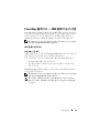
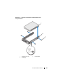
PowerConnect M8024 10 Gb Ethernet Switch I/O Module
The PowerConnect M8024 switch module incorporates two option bays
that support the following modules:
• A 10 Gb Ethernet module with four optical SFP+ connectors
• A 10 Gb Ethernet module with three copper CX4 uplinks
The modules can be used in any combination and are sold separately.
You can initially configure the switch using either of two methods:
• Connect an external management system to the switch using an optional
USB type-A form factor serial cable, and configure the switch using a
terminal application.
• Use the iKVM CMC console (“17th blade”) and the
connect switch-
n
CMC CLI command. For more information, see the CMC user’s guide.
Once an IP address is assigned to the management VLAN or interface and
the switch is connected to a management network, both Telnet and http are
available through the network.

16 Information Update
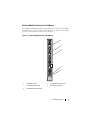
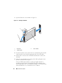
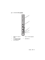
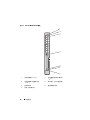
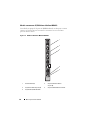
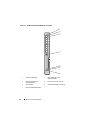
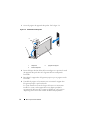
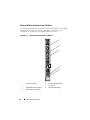
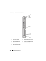
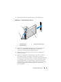
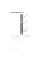
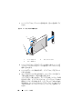
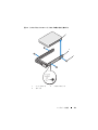
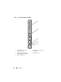
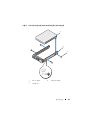
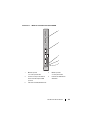
Figure 1-1. PowerConnect M8024 Switch Module
1 optional module with four SFP+
ports
2 optional module with three CX4
ports
3 serial connector for optional USB
type-A form-factor cable
4 module power indicator
5 status/identification indicator
4
1
5
2
3

Information Update 17
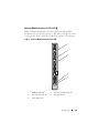
Mellanox M2401G Infiniband Switch I/O Module
The Mellanox M2401G Infiniband switch I/O module includes 24 4x DDR
Infiniband ports. Eight ports are external uplink ports, while 16 internal ports
provide connectivity to the blades in the enclosure.
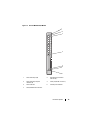
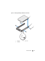
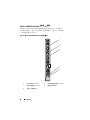
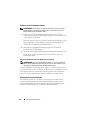
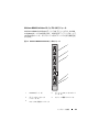
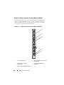
Figure 1-2. Mellanox M2401G Infiniband Switch Module
1 Infiniband ports (8) 2 port link status indicators (8)
3 port activity indicators (8) 4 module power indicator
5 status/identification indicator
4
1
5
2
3

18 Information Update
Brocade M5424 FC8 I/O Module
The Brocade M5424 I/O module includes eight external autosensing Fibre
Channel ports (four ports are enabled in the standard configuration and four
additional ports may be enabled as an optional upgrade), 16 internal ports,
and one serial port with an RJ-45 connector. The external Fibre Channel ports
operate at 8 Gb/sec, 4 Gb/sec, or 2 Gb/sec.
NOTE: CMC firmware version 1.3 is required to support FC8 mezzanine cards
and I/O modules.
NOTE: This Fibre Channel switch module includes Short Wave Small Form Factor
Pluggable (SFP) optical transceivers. To ensure proper functionality, use only SFPs
provided with this module.
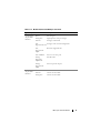
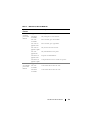
Table 1-5. Mellanox M2401G Infiniband Switch Indicators
Indicator Pattern Description
Link indicator Green, on Physical link established
Green, off No physical link present
Activity
indicator
Amber, on Valid logical link to Infiniband network
established
Amber, blinking Data transfer is occurring
Amber, off No logical link to Infiniband network

Information Update 19
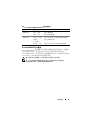
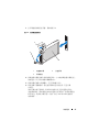
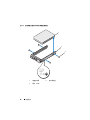
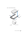
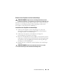
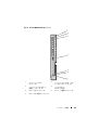
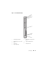
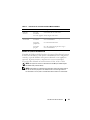
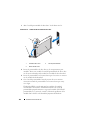
Figure 1-3. Brocade M5424 FC8 I/O Module
1 Fibre Channel port (8) 2 Fibre Channel port status
indicator (8)
3 Fibre Channel port speed
indicator (8)
4 serial port (RJ-45 connector)
5 status indicator 6 module power indicator
7 status/identification indicator
2
4
3
5
6
7
1

20 Information Update
Table 1-6. Brocade M5424 FC8 I/O Module
Indicator Type Pattern Description
Fibre Channel
port status
indicator
Off No signal carrier
Amber on Signal present but not online
Green on Online, but no activity
Green blinking
slowly
Online but segmented
Green blinking
quickly
Internal loopback
Green flickering I/O activity on port
Amber blinking
slowly
Port disabled
Amber blinking
rapidly
Error or fault with port
Fibre Channel
port speed
indicator
Off 2 Gb link established
Green on 4 Gb link established
Amber on 8 Gb link established
Module status
indicator
Off Module is off or enclosure power is off.
Green on All ports are ready for use.
Amber on Module is booting being reset, or ports are offline.
Green/amber
blinking
Diagnostic message is in error log, or
environmental range is exceeded.
Module power
indicator
Off Power to the module is off.
Green Module has power.
Status/
identification
indicator
Blue on Primary module in a stack, if applicable
Blue off Secondary module in a stack
Amber flashing Fault condition in module
La page est en cours de chargement...
La page est en cours de chargement...
La page est en cours de chargement...
La page est en cours de chargement...
La page est en cours de chargement...
La page est en cours de chargement...
La page est en cours de chargement...
La page est en cours de chargement...
La page est en cours de chargement...
La page est en cours de chargement...
La page est en cours de chargement...
La page est en cours de chargement...
La page est en cours de chargement...
La page est en cours de chargement...
La page est en cours de chargement...
La page est en cours de chargement...
La page est en cours de chargement...
La page est en cours de chargement...
La page est en cours de chargement...
La page est en cours de chargement...
La page est en cours de chargement...
La page est en cours de chargement...
La page est en cours de chargement...
La page est en cours de chargement...
La page est en cours de chargement...
La page est en cours de chargement...
La page est en cours de chargement...
La page est en cours de chargement...
La page est en cours de chargement...
La page est en cours de chargement...
La page est en cours de chargement...
La page est en cours de chargement...
La page est en cours de chargement...
La page est en cours de chargement...
La page est en cours de chargement...
La page est en cours de chargement...
La page est en cours de chargement...
La page est en cours de chargement...
La page est en cours de chargement...
La page est en cours de chargement...
La page est en cours de chargement...
La page est en cours de chargement...
La page est en cours de chargement...
La page est en cours de chargement...
La page est en cours de chargement...
La page est en cours de chargement...
La page est en cours de chargement...
La page est en cours de chargement...
La page est en cours de chargement...
La page est en cours de chargement...
La page est en cours de chargement...
La page est en cours de chargement...
La page est en cours de chargement...
La page est en cours de chargement...
La page est en cours de chargement...
La page est en cours de chargement...
La page est en cours de chargement...
La page est en cours de chargement...
La page est en cours de chargement...
La page est en cours de chargement...
La page est en cours de chargement...
La page est en cours de chargement...
La page est en cours de chargement...
La page est en cours de chargement...
La page est en cours de chargement...
La page est en cours de chargement...
La page est en cours de chargement...
La page est en cours de chargement...
La page est en cours de chargement...
La page est en cours de chargement...
La page est en cours de chargement...
La page est en cours de chargement...
La page est en cours de chargement...
La page est en cours de chargement...
La page est en cours de chargement...
La page est en cours de chargement...
La page est en cours de chargement...
La page est en cours de chargement...
La page est en cours de chargement...
La page est en cours de chargement...
La page est en cours de chargement...
La page est en cours de chargement...
La page est en cours de chargement...
La page est en cours de chargement...
La page est en cours de chargement...
La page est en cours de chargement...
La page est en cours de chargement...
La page est en cours de chargement...
La page est en cours de chargement...
La page est en cours de chargement...
La page est en cours de chargement...
La page est en cours de chargement...
La page est en cours de chargement...
La page est en cours de chargement...
La page est en cours de chargement...
La page est en cours de chargement...
La page est en cours de chargement...
La page est en cours de chargement...
La page est en cours de chargement...
La page est en cours de chargement...
La page est en cours de chargement...
La page est en cours de chargement...
La page est en cours de chargement...
La page est en cours de chargement...
La page est en cours de chargement...
La page est en cours de chargement...
La page est en cours de chargement...
La page est en cours de chargement...
La page est en cours de chargement...
La page est en cours de chargement...
La page est en cours de chargement...
La page est en cours de chargement...
La page est en cours de chargement...
La page est en cours de chargement...
La page est en cours de chargement...
La page est en cours de chargement...
La page est en cours de chargement...
La page est en cours de chargement...
La page est en cours de chargement...
La page est en cours de chargement...
La page est en cours de chargement...
La page est en cours de chargement...
La page est en cours de chargement...
La page est en cours de chargement...
La page est en cours de chargement...
La page est en cours de chargement...
La page est en cours de chargement...
La page est en cours de chargement...
La page est en cours de chargement...
La page est en cours de chargement...
La page est en cours de chargement...
La page est en cours de chargement...
La page est en cours de chargement...
La page est en cours de chargement...
La page est en cours de chargement...
La page est en cours de chargement...
La page est en cours de chargement...
La page est en cours de chargement...
La page est en cours de chargement...
La page est en cours de chargement...
La page est en cours de chargement...
La page est en cours de chargement...
La page est en cours de chargement...
La page est en cours de chargement...
La page est en cours de chargement...
La page est en cours de chargement...
La page est en cours de chargement...
La page est en cours de chargement...
La page est en cours de chargement...
La page est en cours de chargement...
La page est en cours de chargement...
La page est en cours de chargement...
La page est en cours de chargement...
La page est en cours de chargement...
La page est en cours de chargement...
La page est en cours de chargement...
La page est en cours de chargement...
La page est en cours de chargement...
La page est en cours de chargement...
La page est en cours de chargement...
La page est en cours de chargement...
La page est en cours de chargement...
La page est en cours de chargement...
La page est en cours de chargement...
La page est en cours de chargement...
La page est en cours de chargement...
-
 1
1
-
 2
2
-
 3
3
-
 4
4
-
 5
5
-
 6
6
-
 7
7
-
 8
8
-
 9
9
-
 10
10
-
 11
11
-
 12
12
-
 13
13
-
 14
14
-
 15
15
-
 16
16
-
 17
17
-
 18
18
-
 19
19
-
 20
20
-
 21
21
-
 22
22
-
 23
23
-
 24
24
-
 25
25
-
 26
26
-
 27
27
-
 28
28
-
 29
29
-
 30
30
-
 31
31
-
 32
32
-
 33
33
-
 34
34
-
 35
35
-
 36
36
-
 37
37
-
 38
38
-
 39
39
-
 40
40
-
 41
41
-
 42
42
-
 43
43
-
 44
44
-
 45
45
-
 46
46
-
 47
47
-
 48
48
-
 49
49
-
 50
50
-
 51
51
-
 52
52
-
 53
53
-
 54
54
-
 55
55
-
 56
56
-
 57
57
-
 58
58
-
 59
59
-
 60
60
-
 61
61
-
 62
62
-
 63
63
-
 64
64
-
 65
65
-
 66
66
-
 67
67
-
 68
68
-
 69
69
-
 70
70
-
 71
71
-
 72
72
-
 73
73
-
 74
74
-
 75
75
-
 76
76
-
 77
77
-
 78
78
-
 79
79
-
 80
80
-
 81
81
-
 82
82
-
 83
83
-
 84
84
-
 85
85
-
 86
86
-
 87
87
-
 88
88
-
 89
89
-
 90
90
-
 91
91
-
 92
92
-
 93
93
-
 94
94
-
 95
95
-
 96
96
-
 97
97
-
 98
98
-
 99
99
-
 100
100
-
 101
101
-
 102
102
-
 103
103
-
 104
104
-
 105
105
-
 106
106
-
 107
107
-
 108
108
-
 109
109
-
 110
110
-
 111
111
-
 112
112
-
 113
113
-
 114
114
-
 115
115
-
 116
116
-
 117
117
-
 118
118
-
 119
119
-
 120
120
-
 121
121
-
 122
122
-
 123
123
-
 124
124
-
 125
125
-
 126
126
-
 127
127
-
 128
128
-
 129
129
-
 130
130
-
 131
131
-
 132
132
-
 133
133
-
 134
134
-
 135
135
-
 136
136
-
 137
137
-
 138
138
-
 139
139
-
 140
140
-
 141
141
-
 142
142
-
 143
143
-
 144
144
-
 145
145
-
 146
146
-
 147
147
-
 148
148
-
 149
149
-
 150
150
-
 151
151
-
 152
152
-
 153
153
-
 154
154
-
 155
155
-
 156
156
-
 157
157
-
 158
158
-
 159
159
-
 160
160
-
 161
161
-
 162
162
-
 163
163
-
 164
164
-
 165
165
-
 166
166
-
 167
167
-
 168
168
-
 169
169
-
 170
170
-
 171
171
-
 172
172
-
 173
173
-
 174
174
-
 175
175
-
 176
176
-
 177
177
-
 178
178
-
 179
179
-
 180
180
-
 181
181
-
 182
182
-
 183
183
-
 184
184
-
 185
185
-
 186
186


dans d''autres langues
- español: Dell PowerEdge M600 Guía del usuario
- Deutsch: Dell PowerEdge M600 Benutzerhandbuch
- 日本語: Dell PowerEdge M600 ユーザーガイド